EP0955740A1 - Système de commande pour studio et méthode d'automatisation d'appareils de levage et d'éclairage utilisé dans le domaine des studios - Google Patents
Système de commande pour studio et méthode d'automatisation d'appareils de levage et d'éclairage utilisé dans le domaine des studios Download PDFInfo
- Publication number
- EP0955740A1 EP0955740A1 EP98108068A EP98108068A EP0955740A1 EP 0955740 A1 EP0955740 A1 EP 0955740A1 EP 98108068 A EP98108068 A EP 98108068A EP 98108068 A EP98108068 A EP 98108068A EP 0955740 A1 EP0955740 A1 EP 0955740A1
- Authority
- EP
- European Patent Office
- Prior art keywords
- studio
- bus
- node
- nodes
- message
- Prior art date
- Legal status (The legal status is an assumption and is not a legal conclusion. Google has not performed a legal analysis and makes no representation as to the accuracy of the status listed.)
- Withdrawn
Links
- 230000005540 biological transmission Effects 0.000 claims 3
Images



Classifications
-
- H—ELECTRICITY
- H04—ELECTRIC COMMUNICATION TECHNIQUE
- H04H—BROADCAST COMMUNICATION
- H04H60/00—Arrangements for broadcast applications with a direct linking to broadcast information or broadcast space-time; Broadcast-related systems
- H04H60/02—Arrangements for generating broadcast information; Arrangements for generating broadcast-related information with a direct linking to broadcast information or to broadcast space-time; Arrangements for simultaneous generation of broadcast information and broadcast-related information
- H04H60/04—Studio equipment; Interconnection of studios
Definitions
- the invention relates to studio control systems and methods for the automation of lifting and lighting equipment used in the studio area, such as lifting devices, chain hoists, brackets, spotlights, dimmers and the like, as well as methods for configuring a studio control system and methods for identifying a node in a studio control system.
- lifting and lighting devices In television studios, a large number of lifting and lighting devices have to be positioned and controlled from a central control computer or a remote control. For example, lifting devices, together with the headlights attached to them, must be positioned vertically and horizontally; the headlights must be adjusted with regard to eight axes (tilting, swiveling, focus, turning the door, four gate flaps) and must be controlled with regard to light intensity and color as well as other effects. These settings are usually not static, but have to be continuous can be changed. Incorrect operation and collisions when positioning the devices must be avoided.
- the central control computer is electrically connected to the various devices, transmits control commands to the devices and manages data on the positions and settings of the devices. Communication takes place via a bus under the central control of the control computer, which sends control commands to the connected devices and receives responses from the devices.
- the control computers, remote controls and lifting and lighting devices connected to the studio bus can be called nodes of the studio control system.
- the first task is to create a studio control system and a process for the automation of lifting and lighting equipment used in the studio area, which do not have the deficits mentioned above.
- the aim is to specify a studio control system and a control method that allows a practically unlimited number of lifting and lighting devices that can be controlled virtually in real time.
- Another disadvantage of the known systems is due to the large number of devices and control units required and used.
- the large number of nodes i.e. of control computers and / or remote controls as well as lifting and lighting devices, all of which must be controlled both jointly and individually and thus supplied directly and individually with the corresponding control commands via the studio bus, make it necessary for each of these nodes to be uniquely addressable in the overall system .
- each node must be assigned a unique address at which it can be reached via the studio control bus.
- the node addresses are usually set manually on the device in each node using DIP switches. This happens before a control unit or device is integrated into the studio. In particular when setting up a large studio system, but also when replacing or adding a device to an existing studio lighting system, errors can easily occur.
- the second task is to provide a method for configuring a studio control system that eliminates the need to assign and set device addresses by the user.
- This second task is independent of the first task, since even in the known studio control systems and methods, a large number of nodes have to be addressed, i.e. is to be addressed.
- the first object is achieved by a studio control system with the features of patent claim 1 and a control method with the features of patent claim 5.
- Advantageous refinements result from the subclaims.
- the studio control system comprises a studio bus for the transmission of messages and a plurality of nodes which are designed for connection to the studio bus and for sending and receiving messages via the studio bus, namely several lifting or lighting devices and at least one control unit for controlling the lifting or lighting devices with the help of messages transmitted via the studio bus.
- the nodes are designed for sending and receiving messages via the studio bus such that when two or more nodes send messages at the same time, the nodes use the content of the message to determine which node continues to send the message.
- the nodes in the studio control system according to the invention are designed for the sending and receiving of messages via the studio bus in such a way that the transmitted messages comprise several fields (P, G, E, S, N) and that when messages are sent simultaneously two or more nodes determine the nodes on the basis of at least one identifier transmitted at the beginning of the message (consisting, for example, of the fields P, G, E, S), which node continues to send the message.
- the identifier of a message By specifying the identifier of a message with the help of one or more fields at the beginning of a message, it can be determined very quickly when a node is transmitting a message whether it can continue the transmission and, on the other hand, a particularly clear structure for those to be transmitted Messages are set up, which can also determine the priority of the message.
- the nodes are designed for sending and receiving messages via the studio bus in such a way that the content of the at least one identifier transmitted at the beginning of the message represents a value which is inversely proportional to the priority of the message.
- An embodiment of the studio control system according to the invention is advantageous in which the nodes are designed for sending and receiving messages via the studio bus in such a way that the nodes send and receive the messages in digital form bit by bit and that when two or more nodes send messages at the same time the nodes, upon sending each bit of the identifier, determine which node continues sending the message. This enables the studio bus to be arbitrated bit by bit.
- the method according to the invention for the automation of lifting and lighting equipment used in the studio area in which messages are transmitted between the lifting or lighting equipment and at least one control unit via a studio bus, provides that when messages are transmitted simultaneously, the content of the messages determines which message will be transmitted further.
- the transmitted messages comprise a plurality of fields (P, G, E, S, N) and is determined when messages are sent at the same time using at least one identifier (P, G, E, S) transmitted at the beginning of the message. which message will be transmitted further.
- the content of the at least one identifier (P, G, E, S) transmitted at the beginning of the message represents a value which is inversely proportional to the priority of the message.
- the messages are sent and received bit by bit in digital form and that when messages are sent at the same time each bit of the identifier is sent, which message is to be transmitted further.
- the second object is achieved by a method according to claim 9 and a studio control system according to claim 13.
- Advantageous refinements result from the subclaims.
- each node is assigned a much shorter node address using the serial number, which in the conventional systems had to be set manually using DIP switches. It is crucial to recognize that the serial number is suitable for configuration, but because of its length it is not suitable for addressing during operation.
- control units In a studio control system with several control units, the control units first mutually transmit a serial number that uniquely identifies them, and each control unit checks whether their serial number is the lowest or the highest serial number of all control units. The assignment and transmission of the node addresses according to steps (c) and (d) is then carried out by the control unit with the lowest serial number or by the control unit with the highest serial number.
- control units advantageously store the serial numbers of the nodes and the node addresses assigned to them, so that each control unit can directly control the controllable nodes.
- the second task is also solved by a studio control system, the nodes of which are designed or adapted to carry out the method described above.
- the nodes are designed or adapted to carry out the method according to the invention regularly by programming the nodes accordingly (firmware).
- the nodes are also advantageously designed or adapted for carrying out the method described above for automating lifting and lighting equipment used in the studio area.
- the adaptation is essentially carried out by appropriate programming of the nodes (firmware).
- serial numbers for the identification of the nodes
- the area of all serial numbers provided for the nodes is divided into at least two areas and queried for each area at the nodes whether the serial number that is uniquely assigned to them lies in the area that the areas in which the serial number of no node does not fall, are no longer checked, and that the areas in which the serial number of at least one node falls, as long as again in at least two Areas divided and for each new area, the nodes are queried as to whether the serial number uniquely assigned to them lies in the area until the serial numbers of the nodes are uniquely identified.
- the division of the serial number ranges and the query at the nodes is advantageously carried out by a control node or a correspondingly adapted (designed) other node.
- a studio control system with a studio bus and a plurality of nodes which are designed for connection to the studio bus and for transmission and reception via the studio bus, they comprise a plurality of lifting or lighting devices and at least one control unit for controlling the lifting or lighting devices with the help of control commands transmitted via the studio bus, the nodes are designed for the implementation of this method.
- the nodes of the studio control system are also designed to carry out one of the methods described above.
- FIG. 1 schematically shows the basic structure of an exemplary embodiment of a studio control system according to the invention, which comprises a studio bus 1a, 1b, 1c, 1d, a control unit 2, two lifting devices 3a and 3b, a plurality of headlights 4a, 4b, 4c and a remote control 5 exists.
- the control unit 2 On the studio bus, which has the main sections 1a, 1b, 1c shown in FIG. 1, the control unit 2, the lifting devices 3a and 3b, the headlights 4a, 4b and 4c and the remote control 5 are either directly or indirectly connected and are available via the Studio bus in connection with each other by sending messages according to the invention via the studio bus or receiving messages sent via the studio bus.
- the type, format and content of the communications are described in more detail below.
- the main sections 1a, 1b and 1c are fixed in the studio and integrated, for example, in a busbar system, so that each connected device can be easily and reliably connected to both the power supply and the studio bus according to the invention.
- a busbar system can be used directly for the construction and operation of a studio control system according to the invention.
- the studio bus can be continued in the lifting devices, as shown in FIG. 1 for example on the first lifting device 3a in the form of a studio bus section 1d.
- the headlights 4a attached to the lifter 3a are directly connected to the studio bus section 1d, as shown in Fig. 1 for the first headlights 4a.
- Both the first lifting device 3a and the first headlights 4a are Designed for direct connection to the bus and have a mostly microprocessor-controlled control device 3a-1 and 4a-1 with a suitably designed and non-volatile program stored therein.
- the lifting devices can be designed such that the studio bus is not continued in the lifting device, as shown in FIG. 1 on the second lifting device 3b.
- the second headlights 4b attached to the lifting device are then not directly connected to the studio bus 1c, but via the second lifting device 3b, which exchanges with the second headlights 4b via a differently designed communication interface, for example in accordance with the RS485 standard for serial interfaces, data and control commands .
- the second lifting device 3b takes over the task of receiving messages for the second headlights 4b via the studio bus and forwarding them to the second headlights 4b and secondly sending messages, own and from the second headlights 4b, via the studio bus.
- the second lifting device 3b is designed accordingly and, for this purpose, has a mostly microprocessor-controlled control device 3b-1 with a correspondingly designed and non-volatile program stored therein.
- a headlight can also be connected directly to the bus, as shown in FIG. 1 for a third headlight 4c and the bus section 1b.
- the third headlight 4c is designed accordingly and, for this purpose, has a mostly microprocessor-controlled control device 4c-1 with an appropriately designed and non-volatile program stored therein.
- a control unit 2 is connected to the studio bus.
- the control unit 2 in the exemplary embodiment consists of a control computer 2a and an interface 2b, via which the control computer 2a is connected to the studio bus.
- the user operates the studio control system according to the invention on the control computer 2a.
- the control computer 2a displays the lighting and lifting technology status of the entire studio on a monitor 2c by displaying the current positions / settings for all devices.
- each lifting or lighting device can be positioned and adjusted via an input device 2d, for example a keyboard and / or a mouse.
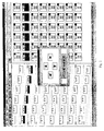
- FIG. 2 shows an example of a monitor image of the control computer 2a, from which the user can obtain the essential information about each lifting device and each headlight.
- the monitor image shown in FIG. 2 shows a studio control system according to the invention, which has more lifting and lighting devices than the exemplary embodiment explained in connection with FIG. 1.
- the control computer 2a which is preferably used as a control unit, allows simple selection and control of the devices via an intuitive user interface on which the lifting and lighting devices are shown in different views.
- the user is supported by a context-sensitive auxiliary system. Individual or multiple linked scenes can be prepared, saved and then set up in the studio independently of the studio. Manual changes to the lifting and lighting equipment are shown directly on the monitor 2c of the control computer 2a shown because changes in the position or the settings are communicated by the devices via the bus.
- control units and devices which are referred to below as nodes, communicate in the form of messages which are sent via the bus.
- each node is authorized to send a message if this should be necessary for any reason.
- lifting devices can be equipped with an absolute encoder for the vertical position, which detects this change when the vertical position is changed manually.
- the control device of the lifting device detects the change detected by the absolute value transmitter and sends a message to the control unit in order to pass on the change.
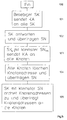
- Fig. 3 the course of communication is shown as an example.
- the control device of the lifting device checks the vertical position by reading out the absolute value encoder, as shown in step 101. If the control device detects a change in the vertical position of the lifting device in step 102, the control device of the lifting device formulates a message in accordance with step 103, the format of which is explained in more detail below.
- the control device of the lifting device sends this message according to step 104 via the studio bus to the control unit or control units and thus disseminates information about the change in the vertical position of the lifting device. Then the returns Control device of the lifting device back to an operation in which the loop 100 is passed.
- step 105 the controller receives the messages sent from other nodes over the bus and checks to see if it is a message that is important to the lifter. If this is the case, the control device initiates the control steps corresponding to the content of the message, for example raising or lowering the lifting device, the transmission of settings or the like.
- the nodes connected to the studio bus and communicating via the studio bus can send a message at any time, which is received by all nodes and which triggers a reaction at one or more nodes.
- the focus is therefore not on a control unit, for example a control computer, and accesses the other nodes via the studio bus; rather, each node has essentially the same authority to access the bus and to transmit messages.
- Which node can ultimately transmit a message with simultaneous bus access by several nodes depends on the identifier (priority) of the message, via which the priority of the message can also be determined, and not on the node.
- the messages according to the invention have a format that is particularly suitable for the requirements of studio control systems, for which an exemplary embodiment is explained below based on the standard bus CAN version 2.0B.
- CAN version 2.0B a detailed description of a network designed for the studio control system according to the invention, in particular with regard to the components and the lower layers of the communication protocol, can be dispensed with here, since this standard bus is for the Application of the invention is suitable.
- Other bus systems are also fundamentally suitable for the application of the invention, but no further details will be given here.
- the messages of the studio control system according to the invention have the basic structure shown in FIG. 4. Auxiliary information such as start and stop characters, delimiters or error detection and error correction codes are not shown, since this information is predetermined by the network system used. At this point, too, express reference is made to the CAN version 2.0B standard.
- the bus access is regulated via the identifier of the message. If two nodes send at the same time, the identifier of the message decides which of the two nodes can transmit its message completely.
- the bitwise bus arbitration method provided by the standard bus CAN version 2.0B can be used to advantage. Thereafter, all nodes can send bit-synchronous messages, even if this enables two or more nodes to occupy the bus almost simultaneously after the bus has not been occupied for a specified period of time.
- each node checks whether the level it has actually placed on the bus is actually present, ie from it itself can be received. If so, the node continues sending its message with the next bit.
- the bit-wise transmission and checking continues until the node has completely transmitted its message or until a level which it has placed on the bus cannot be determined again on the bus.
- the node then stops sending its message and becomes the recipient of the higher priority message sent by another node. After receiving the complete notification from the other node, the node tries to send its notification again.
- the prerequisite for this bus access method is that the identifiers are uniquely assigned. If two messages with the same identifier are sent, it cannot be determined which message may be sent further. On the other hand, it must be ensured that messages from different nodes are sent bit-synchronously. I.e. the first bit of a first message must be placed on the bus at the same time as the first bit of a second message so that a bus assignment can function via bitwise arbitration.
- the studio control system is distinguished by the definition of the individual fields which build up the message (data telegrams), which are shown in FIG. 4.
- the first field "Priority (P)” essentially determines the priority with which the message is sent over the bus.
- P priority
- the following priority levels are distinguished: level description P0 emergency P1 Synchronous groups P2 Control commands from computers to devices P3 Feedback from devices to computers P4 Data exchange between computers P5 Parameterization P6 configuration
- Group (G) is defined in the second field “Group (G)” as follows:
- the second field “Group (G)” also determines the priority of the respective message. This will be explained in more detail below.
- the messages that have the value 0 in the first field P have the highest priority (priority P0).
- the value P0 denotes emergency messages, which can be further differentiated with the help of the second field G. If the value 0 also occurs in the second field G (group G0), this means not only that the message has the highest priority, but that this has it Notification ensures an emergency shutdown of the entire studio system; lifting devices forward the message to the headlights and DMX. If the value 1 occurs in the second field G (group G1), this means an emergency shutdown of one, several or all lifting devices.
- the value 3 in the second field G (group G3) leads to an emergency shutdown of one, several or all headlight brackets and the value 5 in the second field G (group G5) results in an emergency shutdown of one, several or all dimmers / DMX (headlights).
- the priority has the following effects: If a node sends the message for the emergency stop for headlamp brackets, i.e.P0G3, this message is transmitted with a delay if another node sends the message P0G0 or P0G1 around the entire system or around at the same time Stop lifting equipment.
- the third field "Receiver (E)" contains the node address of the node to which the message is directed.
- the fourth field “Sender (S)” contains the address of the node that sends the message.
- the node address is set manually, for example via DIP switches on the device, or automatically determined by the studio control system in a configuration step for each node. With the aid of the receiver field E, one or more devices can also be addressed specifically in the event of emergency messages.
- the fifth field "Message (N)" finally contains the message that the sending node sends to the addressed node or nodes. It should be noted that it is not necessary for all messages to have a message field. For example, the emergency messages described above are valid without a message field.
- the studio control system is configured with these commands.
- this involves setting the node addresses under which the individual nodes, i.e. the devices and control units can be addressed after configuration.
- the configuration of a multi-node studio system will now be described in detail with reference to FIG. 5.
- the solution of the second task can advantageously be used together with the previously described solution of the first task, but represents an independent solution idea, the can also be used with conventional studio control systems.
- the serial numbers of the nodes are used for the first identification and configuration.
- the serial number is a device-specific, unique identification of each individual node, i.e. understood every control computer, every remote control and every lifting and lighting device that can be used in the studio system; corresponding serial number systems are known.
- the serial number is available in a non-volatile memory of the node in electronic form or can be provided so that the serial number can be processed by the nodes during configuration and during operation.
- the serial numbers are generally not suitable for addressing the nodes in operation, since the transmission and detection of the usually very long serial numbers is too complex overall.
- the serial numbers are only used to allow a configuration to run initially, for example when the studio system is switched on (for the first time), in the event of a reset of the studio system or when a node is added to an already configured system, by means of which each or the newly added node a unique, much shorter node address is assigned.
- the task of assigning the node addresses is carried out by a control node, since usually only this type of node is designed accordingly.
- the lifting and lighting devices that are controlled by the control nodes are usually not suitable for performing this task take over.
- the control nodes are, for example, control computers or remote controls.
- a studio control system (cf. FIG. 1) with a studio bus (1a, 1b, 1c, 1d) and several nodes, which are designed for connection to the studio bus and for sending and receiving via the studio bus, and which are lifted - or lighting devices (3a, 3b; 4a, 4b, 4c) and at least one control unit (2; 5) for controlling the lifting or lighting devices with the aid of control commands transmitted via the studio bus
- the following configuration steps are carried out:
- Each node sends a unique serial number to the control unit via the studio bus.
- the control unit receives the serial numbers of the nodes and assigns a unique node address to each node.
- the control unit sends the assigned node address to each node via the studio bus, the node being addressed via the serial number.
- Each node receives the assigned node address and stores it in such a way that it can be addressed via the stored node address.
- any control node SK sends a configuration request KA (step 101), for example in the form of the previously described message P6G1SnN (where N identifies the control nodes), to all control nodes SK connected to the studio control bus are connected.
- the control nodes respond to the configuration request KA with a configuration response (step 102), for example in the form of the previously described message P6G2SnN (where N can contain information about a node address that may still be present).
- Each control node SK transmits its own serial number SN both in the configuration request and in the configuration response.
- the control node SK min with the lowest (or highest) serial number SN min can carry out the configuration and, in addition, a configuration request KA to all Send nodes with which not only the control nodes but also all other nodes, that is to say the lifting and lighting devices, are caused to delete the node addresses that are still present (step 103).
- the message P6G1SnN (where N identifies all nodes) can also be used here, for example, in the form described above.
- all addressed nodes of the studio system delete the node addresses stored with them and send a configuration response (step 104), for example in the form of the previously described message P6G2SnN (where N contains information about the device type).
- the configuration response of each node contains its serial number SN, so that in the control node SK min carrying out the configuration, if desired, but also in all other control nodes, all the serial numbers accumulate and are temporarily stored.
- the control node SK min carrying out the configuration assigns a unique short node address to each node of the studio system and transmits the node address to the respective node (Step 105).
- the control node SK min uses the temporarily stored serial numbers SN to identify the nodes that cannot be addressed at this point in time via a short node address.
- the control node SK min carrying out the configuration sends a message to each node, for example in the form of the previously described message P6G3SnN (where N contains the node address), with which the control node transmits the new (short) node address to the addressed node .
- the respective addressed node receives this message, saves the node address and can then be addressed (addressed) using the short node address.
- the assigned node addresses can now be used.
- An analog estimate of the time required for the above-mentioned studio system results in approximately 2655 ms for the transmission of the parameters, so that taking into account dead times, a studio system of the above-mentioned order of magnitude is completely configured and parameterized within approximately 10 to 20 s after each power-up .
- the node sends a configuration response, for example with the message P6G2SnN, without being prompted by a control node, and repeats this at a predetermined time interval until the control node with the lowest (or highest) serial number SK min , the had previously carried out the configuration of the overall system, transfers a node address to the newly added node, for example using the message P2G3SnN (N is the new short node address, n the serial number SN of the node).
- the newly added node receives this message, saves the short node address assigned in it and can then be addressed (addressed) using the short node address.
- the assigned node address can now be used.
- adding a node to an already configured system also means resetting a node, which is required, for example, because of a node malfunction or caused by an unintentional interruption in the power supply.
- a reset i.e. resetting to an initial state is no longer accessible to the node under the short node address assigned to it, provided that the relevant data is not temporarily stored or other countermeasures are taken.
- the previously described individual configuration can be carried out, thereby avoiding a new configuration of the overall system.
- the second lifting device 3b In the description of the studio control system shown schematically in FIG. 1, it was explained for the second lifting device 3b that the headlights 4b connected to the second lifting device 3b are not directly connected to the studio bus 1c and that another interface, for example a serial interface, is between the lifting device and the headlights can be provided.
- the second lifting device 3b In order to be able to transmit control commands to the headlight, the second lifting device 3b must be able to identify and address the connected headlights 4b.
- dynamic addressing which is achieved on the basis of the serial number of the headlight, is advantageous.
- the serial number of the headlight bracket must be unique and can have the following structure, for example: 7 bit manuf. No. 7 bit device type 21 bit freely selectable number
- the manufacturer number (manufacturer no.) Identifies the manufacturer of the headlight.
- the code number for the device type can be freely assigned by the manufacturer, but must be made known so that an identification or classification can also be made by others.
- the freely selectable number can be freely assigned by the manufacturer; however, the manufacturer can only assign the freely selectable number once for a device type.
- This serial number system is also suitable for use in the previously described method for configuring a studio control system, even if serial numbers are assigned to the other nodes. A distinction can be made about the device type.
- the second lifting device 3b searches for connected headlight brackets and assigns a unique address to each bracket. So that not all possible serial numbers have to be queried individually, the entire range of possible serial numbers is divided into two or more areas. The second lifting device 3b then checks the serial number ranges and asks the headlamp brackets whether ironing with a serial number is present in the area in question. If a bracket detects that its serial number is in the range queried, the bracket sends a signal to the lifting device 3b, which can be very short, for example a break signal.
- the serial number ranges in which no feedback from a headlamp bracket to the lifting device occurs within a certain period of time (timeout) are no longer checked by the lifting device.
- the areas in which the serial number of more than one headlight bracket falls are determined by the lifting device 3b based on the multiple Feedback recognized by the headlight bracket. These areas are subdivided and checked again.
- the area between two serial numbers is queried via a broadcast command by transmitting the two serial numbers to the headlight bracket.
- the two transmitted serial numbers are included in the range. If exactly one serial number is to be queried, this serial number is used twice. If the serial number of a headlight is in the area and no address has been assigned to this bracket, the bracket answers the serial number request with a break signal of 2 character lengths. After the lifting device 3b has determined the serial numbers of the connected headlights 4b, a unique address can be assigned to each headlight. Headlights that have already been assigned an address no longer respond to the query of the serial number ranges. This makes it quicker to recognize headlamp brackets that are attached during operation.
- the headlamp bracket can be identified very quickly based on the (very long) serial numbers.
- n headlights and serial numbers with a length of m bits are maximum (2 xnx (m - n + 1)) + (2 n - 1) Query steps necessary.
- max. 127 removal steps required.
- the procedure described here is suitable for the identification of headlight brackets and other nodes in a studio control system, in general, independently of the previously described methods.
- the check can be carried out by a control node.
Landscapes
- Engineering & Computer Science (AREA)
- Signal Processing (AREA)
- Circuit Arrangement For Electric Light Sources In General (AREA)
- Non-Portable Lighting Devices Or Systems Thereof (AREA)
Priority Applications (2)
| Application Number | Priority Date | Filing Date | Title |
|---|---|---|---|
| EP98108068A EP0955740A1 (fr) | 1998-05-04 | 1998-05-04 | Système de commande pour studio et méthode d'automatisation d'appareils de levage et d'éclairage utilisé dans le domaine des studios |
| JP11126433A JP2000115101A (ja) | 1998-05-04 | 1999-05-06 | スタジオ制御システム |
Applications Claiming Priority (1)
| Application Number | Priority Date | Filing Date | Title |
|---|---|---|---|
| EP98108068A EP0955740A1 (fr) | 1998-05-04 | 1998-05-04 | Système de commande pour studio et méthode d'automatisation d'appareils de levage et d'éclairage utilisé dans le domaine des studios |
Publications (1)
| Publication Number | Publication Date |
|---|---|
| EP0955740A1 true EP0955740A1 (fr) | 1999-11-10 |
Family
ID=8231875
Family Applications (1)
| Application Number | Title | Priority Date | Filing Date |
|---|---|---|---|
| EP98108068A Withdrawn EP0955740A1 (fr) | 1998-05-04 | 1998-05-04 | Système de commande pour studio et méthode d'automatisation d'appareils de levage et d'éclairage utilisé dans le domaine des studios |
Country Status (2)
| Country | Link |
|---|---|
| EP (1) | EP0955740A1 (fr) |
| JP (1) | JP2000115101A (fr) |
Cited By (1)
| Publication number | Priority date | Publication date | Assignee | Title |
|---|---|---|---|---|
| EP1585241A2 (fr) | 2004-03-26 | 2005-10-12 | Harman International Industries, Incorporated | Système de gestion d'équipement audio |
Citations (2)
| Publication number | Priority date | Publication date | Assignee | Title |
|---|---|---|---|---|
| DE3722752A1 (de) * | 1987-07-09 | 1989-01-19 | Engel Ludwig Dipl Ing Bidovsky | Einrichtung zur einstellung, speicherung und zum abruf beliebig vieler fester und variabler einstellgroessen an elektrischen geraeten |
| DE4124794A1 (de) * | 1991-07-26 | 1993-01-28 | Werner Mielke | Beleuchtungsanlage |
-
1998
- 1998-05-04 EP EP98108068A patent/EP0955740A1/fr not_active Withdrawn
-
1999
- 1999-05-06 JP JP11126433A patent/JP2000115101A/ja not_active Withdrawn
Patent Citations (2)
| Publication number | Priority date | Publication date | Assignee | Title |
|---|---|---|---|---|
| DE3722752A1 (de) * | 1987-07-09 | 1989-01-19 | Engel Ludwig Dipl Ing Bidovsky | Einrichtung zur einstellung, speicherung und zum abruf beliebig vieler fester und variabler einstellgroessen an elektrischen geraeten |
| DE4124794A1 (de) * | 1991-07-26 | 1993-01-28 | Werner Mielke | Beleuchtungsanlage |
Non-Patent Citations (2)
| Title |
|---|
| BORK R ET AL: "DIE NEUEN TECHNISCHEN STUDIOEINRICHTUNGEN BEIM BR TEIL 3. BELEUCHTUNGSTECHNISCHE EINRICHTUNGEN", FERNSEH UND KINOTECHNIK, vol. 44, no. 4, 1 January 1990 (1990-01-01), pages 175 - 178, 180, XP000115678 * |
| LUDWIG L: "BELEUCHTUNGSTECHNISCHE EINRICHTUNGEN ZWEIER NEUER PRAESENTATIONS-STUDIOS DES SUEDWESTFUNKS", FERNSEH UND KINOTECHNIK, vol. 46, no. 11, 1 November 1992 (1992-11-01), pages 755 - 758, XP000322391 * |
Cited By (9)
| Publication number | Priority date | Publication date | Assignee | Title |
|---|---|---|---|---|
| EP1585241A2 (fr) | 2004-03-26 | 2005-10-12 | Harman International Industries, Incorporated | Système de gestion d'équipement audio |
| EP1585241A3 (fr) * | 2004-03-26 | 2007-12-05 | Harman International Industries, Incorporated | Système de gestion d'équipement audio |
| EP1585240A3 (fr) * | 2004-03-26 | 2008-02-13 | Harman International Industries, Incorporated | Méthode et système pour la communication entre dispositifs relatifs au traitement de signaux sonores |
| US7689305B2 (en) | 2004-03-26 | 2010-03-30 | Harman International Industries, Incorporated | System for audio-related device communication |
| US7725826B2 (en) | 2004-03-26 | 2010-05-25 | Harman International Industries, Incorporated | Audio-related system node instantiation |
| US7742606B2 (en) | 2004-03-26 | 2010-06-22 | Harman International Industries, Incorporated | System for audio related equipment management |
| US8078298B2 (en) | 2004-03-26 | 2011-12-13 | Harman International Industries, Incorporated | System for node structure discovery in an audio-related system |
| US8249071B2 (en) | 2004-03-26 | 2012-08-21 | Harman International Industries, Incorporated | Audio related system communication protocol |
| US8473844B2 (en) | 2004-03-26 | 2013-06-25 | Harman International Industries, Incorporated | Audio related system link management |
Also Published As
| Publication number | Publication date |
|---|---|
| JP2000115101A (ja) | 2000-04-21 |
Similar Documents
| Publication | Publication Date | Title |
|---|---|---|
| EP1519634B1 (fr) | Convertisseur de données pour une installation d'éclairage et procédé de fonctionnement d'une installation d'éclairage | |
| DE102004061294B4 (de) | Verfahren zur Programmierung eines Betriebsgerätes für Leuchtmittel, Schnittstelle für ein Betriebsgerät für Leuchtmittel und Betriebsgerät für Leuchtmittel | |
| DE69218016T2 (de) | Verfahren zum Verarbeiten von Steueraufträgen | |
| WO1999048251A1 (fr) | Procede de mise en service d'un systeme bus et systeme bus en question | |
| EP2545751B1 (fr) | Système d'équipement de bâtiment utilisant un bus de communication présentant un branchement en série | |
| EP0833425A2 (fr) | Système de communication pour un réseau câblé d'alimentation | |
| EP1659832A2 (fr) | Méthode pour allouer des adresses de format réduit dans des installations d' éclairage | |
| DE4422215A1 (de) | Steuersystem für mehrere verteilt anzuordnende Verbraucher, sowie Verfahren zum In-Betrieb-Setzen eines solchen Steuersystems | |
| EP1292175B1 (fr) | Management d'un système lumineux avec starter électronique | |
| DE3611949C2 (fr) | ||
| DE69434976T2 (de) | Rangadressenzuweiseung in einem modulsystem | |
| EP1480498A2 (fr) | Procédé pour commander une installation d'éclairage | |
| DE102008004798B4 (de) | Konfigurations- und Anzeigemodul für busvernetzte Teilnehmer | |
| EP3251469B1 (fr) | Procédé pour faire fonctionner des appareils dans un système d'éclairage | |
| EP0958533B1 (fr) | Terminal audio-actif d'un systeme de communication, procede de communication et systeme de communication equipe de terminaux audio-actifs de ce type | |
| DE102005057068A1 (de) | Steuerungssystem für mehrere verteilt angeordnete Verbraucher, insbesondere für Lampenbetriebsgeräte, sowie Verfahren zur Inbetriebnahme | |
| DE102004007057B4 (de) | Verfahren zur Übertragung eines elektronischen digitalen Signals | |
| DE102021116895A1 (de) | System zur Gebäudeautomatisation | |
| DE69125924T2 (de) | Lokales Kommunikationssystem und Rahmenbilder einschliesslich eines programmierbaren Adressgenerators | |
| DE29806094U1 (de) | Beleuchtungssystem mit Bedienelement | |
| DE69711904T2 (de) | Verteiltes serielles steuersystem | |
| DE202008012029U1 (de) | Bussystem | |
| WO2005107173A1 (fr) | Dispositif pour attribuer des adresses dans un systeme de bus de terrain normalise | |
| WO2008040390A1 (fr) | Système d'éclairage et procédé de fonctionnement d'un système d'éclairage | |
| DE10208219B4 (de) | Koppler für ein Bussystem und Verfahren zur Informationsverarbeitung in einem Bussystem |
Legal Events
| Date | Code | Title | Description |
|---|---|---|---|
| PUAI | Public reference made under article 153(3) epc to a published international application that has entered the european phase |
Free format text: ORIGINAL CODE: 0009012 |
|
| AK | Designated contracting states |
Kind code of ref document: A1 Designated state(s): DE GB IT |
|
| AX | Request for extension of the european patent |
Free format text: AL;LT;LV;MK;RO;SI |
|
| 17P | Request for examination filed |
Effective date: 19991209 |
|
| AKX | Designation fees paid |
Free format text: DE GB IT |
|
| STAA | Information on the status of an ep patent application or granted ep patent |
Free format text: STATUS: THE APPLICATION HAS BEEN WITHDRAWN |
|
| 18W | Application withdrawn |
Effective date: 20050629 |