EP1519634B1 - Convertisseur de données pour une installation d'éclairage et procédé de fonctionnement d'une installation d'éclairage - Google Patents
Convertisseur de données pour une installation d'éclairage et procédé de fonctionnement d'une installation d'éclairage Download PDFInfo
- Publication number
- EP1519634B1 EP1519634B1 EP04019088A EP04019088A EP1519634B1 EP 1519634 B1 EP1519634 B1 EP 1519634B1 EP 04019088 A EP04019088 A EP 04019088A EP 04019088 A EP04019088 A EP 04019088A EP 1519634 B1 EP1519634 B1 EP 1519634B1
- Authority
- EP
- European Patent Office
- Prior art keywords
- data converter
- operating means
- lamp operating
- control device
- central control
- Prior art date
- Legal status (The legal status is an assumption and is not a legal conclusion. Google has not performed a legal analysis and makes no representation as to the accuracy of the status listed.)
- Expired - Lifetime
Links
Images

Classifications
-
- H—ELECTRICITY
- H05—ELECTRIC TECHNIQUES NOT OTHERWISE PROVIDED FOR
- H05B—ELECTRIC HEATING; ELECTRIC LIGHT SOURCES NOT OTHERWISE PROVIDED FOR; CIRCUIT ARRANGEMENTS FOR ELECTRIC LIGHT SOURCES, IN GENERAL
- H05B47/00—Circuit arrangements for operating light sources in general, i.e. where the type of light source is not relevant
- H05B47/10—Controlling the light source
- H05B47/175—Controlling the light source by remote control
- H05B47/18—Controlling the light source by remote control via data-bus transmission
- H05B47/183—Controlling the light source by remote control via data-bus transmission using digital addressable lighting interface [DALI] communication protocols
Definitions
- the invention relates to a method for operating a lighting system by means of a data converter according to the preamble of patent claim 1 and a corresponding data converter.
- the Publication WO 02/41671 A2 describes a lighting system with a plurality of lamp resources and a central control device for the lamp resources, wherein the lamp operating means have addressable interfaces, are communicated via the digital data with the central control device. This communication takes place in accordance with the standardized so-called DALI protocol.
- DALI stands for Digital Addressable Lighting Interface.
- the publication WO 03/077610 A1 describes an initialization method for a wireless controlled lighting system.
- a disadvantage of the lighting systems whose central control devices communicate with the lamp resources according to the DALI protocol is that their address memory is limited to sixty-four individual addresses and sixteen group addresses.
- the maximum current carrying capacity of the interface of the central control device is only 250 mA. Thereby, the maximum number of connectable to the central control device lamp resources is limited accordingly.
- the device according to the invention which is referred to here as a data converter, has a data input for communication of the data converter with a central control device of the lighting system, a data output for communication of the data converter with lamp resources and an evaluation unit for evaluating the data received from the central control device and for control and monitoring the functions of the lamp resources.
- the lamp resources are, for example, electronic ballasts for low-pressure or high-pressure discharge lamps, transformers for the operation of low-voltage halogen incandescent lamps or driver circuits for light-emitting diodes.
- lamps is used in the following representative of all types of electrically operated bulbs.
- the data converter according to the invention can be controlled by the central control device in the same way as a lamp operating means.
- the evaluation unit of the data converter converts these control signals of the central control device into commands for controlling the lamp operating means controlled by the data converter.
- the data converter according to the invention behaves in relation to the central control device Addressing and control as a single lamp resource.
- the data output of the data converter according to the invention is designed in such a way that commands for controlling and monitoring its functions can be transmitted via this data output to many lamp resources, these commands being generated by the evaluation unit of the data converter according to the invention as a function of the control signals of the central control device.
- This allows the number of lamp resources in the lighting system, whose function is controllable by means of the central control device can be increased.
- the maximum permissible interface current of the central control device is not exceeded since the data converter according to the invention behaves like a lamp operating medium relative to the central control device and provides the interface current for the lamp operating means controlled by the data converter itself at its data output.
- the data converter advantageously has a non-volatile storage means.
- the data input of the data converter is preferably designed as a multifunctional input, which can receive both digital and analog control signals, which are converted by the evaluation unit of the data converter into commands for the controlled by him lamp resources, as for example in the published patent application WO 01/52607 A1 has been described.
- the data converter according to the invention is not only compatible with a central control device which communicates according to the standardized DALI protocol, but in the simplest case the central control device can even be a push button.
- the data converter according to the invention is formed switchable between at least two different operating modes.
- At least some lamp operating means are controlled and controlled by a data converter receiving and evaluating the control signals generated by the central control device and depending on the result Converts evaluation into commands for controlling the lamp resources controlled by the data converter.
- a data converter receiving and evaluating the control signals generated by the central control device and depending on the result Converts evaluation into commands for controlling the lamp resources controlled by the data converter.
- the control signals received by the central control device are converted by the evaluation unit of the data converter into similar commands for all the lamp operating means controlled by the data converter.
- all of the lamp resources controlled by the data converter are controlled in the same manner, that is, the associated lamps can be simultaneously turned on and off and dimmed.
- the aforementioned lamp resources and their lamps are automatically grouped together.
- a particular advantage of this operating mode is that, instead of a central control device communicating according to the standardized DA-LI protocol, a pushbutton can also be used as the central control device to control the data converter and the lamp operating means controlled by it, since the data converter according to the invention preferably both digital and analog control signals can receive and evaluate.
- the control signals emitted by the central control device are received and evaluated by the data converter in accordance with a group affiliation of the lamp operating means controlled by the data converter from these lamp operating means.
- the second mode of operation allows the grouping of the lamp resources to be extended to a greater number of lamp resources than could be operated solely by the central controller.
- a commissioning process of the data converter is first started during the commissioning phase of the lighting system to the monitored by the data converter Lampenbebsebsittel with To provide address codes, and then a commissioning process of the central control device is started to provide the data converter and any, directly controlled by the central control device lamp resources with address codes, wherein for grouping the data controlled by the data converter lamp resources, the data converter from the central control device is selected as many times until all of the data converter controlled lamp resources are divided into groups, and wherein for each selection of the data converter successively controlled by the data converter lamp resources is assigned to a lamp resource group.
- the grouping of the lamp resources can be extended to the lamp resources controlled by the data converter.
- lamp resources controlled directly by the central control device can thereby be combined with lamp operating means controlled by the data converter in a lamp resource group to be jointly controlled.
- the evaluation unit of the data converter preferably comprises a microcontroller in order to enable a program-controlled evaluation of the control signals received from a central control device and monitoring of the lamp operating means connected to the data output of the data converter.
- the data converter advantageously performs independent status monitoring of the lamp operating means connected to its data output. This ensures that malfunctions can also be detected in the case of the lamp operating means controlled by the data converter, even though the data converter only receives the same control signals from the central control device as each lamp operating means directly connected to the central control device.
- Queries of the central control device for the status of the lamp operating means are advantageously answered by the data converter for the lamp operating means connected to the data output of the data converter in order to ensure that the feedback to the central control device takes place within the permissible time window provided for this purpose.
- the data converter performs the aforementioned status monitoring cyclically, in regular time intervals to have the corresponding values in queries of the central control device for the status of the lamp resources for the feedback ready.
- the data converter according to the invention is preferably able to detect the type of lamp operating means connected to its data output.
- the data converter can evaluate queries of a central control device according to the properties of the lamp operating means and answer them for the lamp operating means controlled by it.
- queries of a central control device according to the characteristics of the lamp resources for the lamp resources connected to the data output of the data converter are answered by the data converter with a predetermined default value for the respective queried property of the lamp resources if the lamp resources controlled by the data converter differ with respect to the respective retrieved property ,
- the default value is advantageously chosen to be compatible with all types of lamp resources. This ensures that the central control device does not respond with an error message due to a lack of feedback on their query.
- the abovementioned queries of the central control device for the lamp operating means connected to the data output of the data converter are preferably answered by the data converter with a reference value for the respective queried property
- the data converter acting as Reference value uses the value of the respective retrieved property of a lamp operating means selected by the data converter of the lamp operating means connected to its data output.
- the data converter selects one of the lamp resources that it controls as the reference device for one or more properties, for example for the maximum dimming range, and returns its value for this property or characteristics to the central control device.
- the aforementioned queries of the central control device can be correctly answered by the data converter for the lamp resources controlled by it.
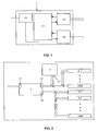
- the data converter 10 has a voltage supply unit 11 which can be connected to the mains voltage and supplies the data converter with electrical energy.
- the data converter 10 has a data input 12, which is connectable to an output of a central control device of a lighting system, and a data output 13, which is connectable to a plurality of lamp operating means.
- the data received at the data input 12 are evaluated by the downstream evaluation unit 14 of the data converter 10 and converted into commands for the lamp operating means connected to the data output 13.
- the evaluation unit 14 is designed as a programmable microcontroller.
- the voltage supply unit 11 provides via the data output 13 the interface current for the communication with the lamp operating means connected to the data output 13. Both the communication of the data converter 10 with the central control device via the data input 12 and its communication with the lamp operating means connected to the data output 13 are bidirectional.
- FIG. 2 shows a schematic representation of a lighting system with a central control device 2, a data converter 1, the first lamp operating means 3.1 to 3.63 and second lamp resources 4.1 to 4.64.
- the control output 21 of the central control device 2 is connected via lines to the first lamp operating means 3.1 to 3.63 and to the data converter 1.
- the first lamp operating means 3.1 to 3.63 and the data converter 1 are connected in parallel.
- the second lamp operating means 4.1 to 4.64 are connected to the data output 13 of the data converter 1. They are also connected in parallel.
- the first lamp operating means 3.1 to 3.63 are directly controlled by the central control device, while the second lamp operating means 4.1 to 4.64 are controlled by the data converter 1, in response to the control signals which the data converter 1 receives at its data input 12 from the central control device 1 ,
- the lamps 3.1 to 3.63 and 4.1 to 4.64 are ballasts for discharge lamps, transformers for low-voltage halogen incandescent lamps and driver circuits for light-emitting diodes. Accordingly, the lamp bulbs the discharge lamp, light bulb and LED are subsumed.
- the central control device 2 communicates control signals according to the standardized DALI protocol via its control output 21 with the sixty-three lamp operating means 3.1 to 3.63 connected thereto and the data converter 1.
- Each of the sixty-three lamp operating means 3.1 to 3.63 and the data converter 1 has an address code comprising sixty-four individual addresses Address supply of the central control device 2.
- these lamp resources 3.1 to 3.63 and the data converter 1 group address codes from the sixteen group addresses comprehensive group address resource of the central control device 2 assigned to the individual lamp resources 3.1 to 3.63 and possibly the data converter 1 to jointly controlled groups summarize.
- the groups summarized lamp resources or their bulbs are simultaneously switched on, off and dimmed.
- FIG. 2 schematically illustrated lighting system, which correspond to two different operating modes of the data converter 1.
- the central control device 2 communicates with the data converter 1 in the same way as with the first lamp operating means 3.1 to 3.63.
- Digital control signals which the data converter 1 receives at its data input 13 from the central control device 2 are evaluated by the evaluation unit 14 of the data converter 1 and converted into digital commands, which are communicated via the data output 13 to all sixty-four second lamp operating means 4.1 to 4.64 connected thereto ,
- the second lamp resources 4.1 to 4.64 are not individually, but only responsive and controllable as a group.
- the data converter 1 can answer a status query of the central control device 2 for the lamp resources 4.1 to 4.64 only across groups.
- the data converter 1 will report only the presence of a defect to the central control device 2, but without being able to determine the number of defective lamps or lamp resources 4.1 to 4.64 and the defective lamps or To locate lamp resources 4.1 to 4.64.
- Individually addressable and controllable are only the first lamp operating means 3.1 to 3.63 connected directly to the central control device 2.
- the advantage of the first mode of operation is that no special commissioning of the data converter and its downstream lamp resources 4.1 to 4.64 is required and the data converter 1 is compatible with all central control devices with DALI interface 21.
- the disadvantage is that this operating mode does not allow grouping of the lamp operating devices 4.1 to 4.64.
- the central control device 2 communicates with the data converter 1 in the same manner as with the first lamp operating means 3.1 to 3.63.
- Digital control signals which the data converter 1 receives at its data input 13 from the central control device 2 are evaluated by the evaluation unit 14 of the data converter 1 and converted into digital commands, which are communicated via the data output 13 but not generally to all sixty-four second lamp resources 4.1 to 4.64 connected thereto, but selectively to only a few predetermined ones of the sixty-four second lamp resources 4.1 to 4.64. That is, the second lamp operating means 4.1 to 4.64 are controlled by the central control device 2 and the data converter 1 according to their group membership, unlike the above-described first operation mode.
- a prerequisite for the division of the second lamp resources 4.1 to 4.64 in groups is that initially during a startup phase, the second lamp resources 4.1 to 4.64 are provided with an address code to make them distinguishable for the data converter 1 and the control device 2.
- the commissioning without external intervention by the data converter 1 is automatically started and carried out as soon as the data converter 1 detects lamp resources without an address, which are connected to its data output 13.
- this startup can also be started via a button located on the data converter 1 or via a special command of the central control device.
- the data converter 1 assigns to each of the lamp operating means 4.1 to 4.64 an individual address code from its address supply which each lamp operating means 4.1 to 4.64 permanently stores.
- the second lamp operating means 4.1 to 4.64 can be distinguished for the data converter 1. Subsequently, the commissioning of the central control device 2 and connected to its control output 21 lamp resources 3.1 to 3.63 and the data converter 1 is started.
- the lamp resources 3.1 to 3.63 and the data converter 1 are divided into a maximum of sixteen groups, according to the available group address supply of the central control device 2, by each lamp resources 3.1 to 3.63 and the data converter 1 is assigned by the central control device 2 each at least one of the sixteen group addresses.
- the adoption of the respective group address codes by the lamp resources 3.1 to 3.63 and 4.1 to 4.64 can be achieved, for example, by successively populating the lamp resources 3.1 to 3.63 and 4.1 to 4.64 according to their group membership, such as for example in the published patent application EP 0 639 938 A1 is described.
- Another, preferred way of group assignment is the group addresses the individual lamp resources 3.1. to 3.63 and assign the data converter 1 via the controls of the central control device 2.
- each lamp operating means 3.1 to 3.63 selected exactly once by the central control device 2 and assigned to him by means of the controls at least one group address.
- the data converter 1 is selected or called up sixty-four times by the central control device 2 during the group assignment, corresponding to the number of the lamp operating means 4.1 to 4.64 connected to its data output 13. Each time the data converter 1 is called by the central control device 2, at least one group address is successively assigned to one of the lamp operating means 4.1 to 4.64 connected to the data output 13 of the data converter 1. That is, at the first call of the data converter 1, at least one group address is assigned to the lamp resource 4.1 and at the second call of the data converter 1 the lamp resource 4.2 is assigned at least one group address and so on until all four sixty lamp resources 4.1 to 4.64 are provided with group addresses.
- the data converter 1 extends the group addresses assigned to it by the central control device 2 in accordance with the above rule to the second lamp operating means 4.1 to 4.64.
- the individual lamp resources 3.1 to 3.63 and 4.1 to 4.64 store the group addresses allocated to them in a non-volatile memory means, for example in an EEPROM.
- the lamp operating means 4.1 to 4.64 connected to the data output 13 of the data converter 1 can also be divided into groups. It is even possible to combine first lamp resources 3.1 to 3.63 and second lamp resources 4.1 to 4.64 in the same group.
- the first lamp operating group consists of the lamp operating means 3.1, 4.1 and 4.2
- a control command determined for this lamp operating group will be sent from the central control device 2 via the control output 21 to all first lamp operating means 3.1 to 3.63 and via the data converter 1 to all second lamp operating means 4.1 to 4.64 sent.
- the lamp operating means 3.1, 4.1 and 4.2 execute this control command, since only the group address stored by these lamp operating means 3.1, 4.1 and 4.2 coincides with the group address indicated in the control command.
- the data converter 1 operates in this case as a slave, that is, it passes the control command to the connected to its data output 13 lamp operating 4.1 to 4.64 on.
- the data converter 1 With respect to the connected to its data output 13 lamp resources 4.1 to 4.64, the data converter 1, however, works like a master, that is, for example, feedback the second lamp resources 4.1 to 4.64 to their current status to corresponding requests of the central control device 2 are from the data converter 1 and not from the central control device 2 evaluated.
- the central control device 2 evaluates corresponding feedback from the first lamp operating means 3.1 to 3.63.
- the data converter 1 independently carries out a status monitoring of these lamp operating means by cyclically querying the downstream lamp operating means 4.1 to 4.64. On the basis of this status image, the data converter 1 can answer queries of the central control device 2 immediately, without a time delay.
- the data converter 1 is preset to the first operating mode. In order to place it in the second operating mode, it must be switched over by actuating a switch arranged on the housing of the data converter 1 or by means of a special command of the central control device 2. The actuation of this switch or the aforementioned command initiates the startup procedure explained above.
- the data converter 1 is configured such that it can receive and evaluate both digital and analog control signals at its data input 12.
- the standardized DALI protocol working central control device 2 which acts on the data input 12 of the data converter 1 with digital control commands, can also operate with analog control commands central control device, such as a button 5 according to the schematic representation in FIG FIG. 3 be used.
- the data input 12 of the data converter 1 is connected via the button 5 to the AC line voltage N, L.
- a total of sixty-four parallel lamp operating means 6.1 to 6.64 are connected.
- the evaluation unit 14 generates in response to the operation of the button 5, the duration of the button operation and the current operating state of the lamp operating 6.1 to 6.64 control commands for the connected to the data output 13 lamp operating 6.1 to 6.64.
- all the lamp operating means 6.1 to 6.64 are simultaneously controlled in the same way. This means that the lamps operated by the lamp operating means 6.1 to 6.64 are switched on and dimmed simultaneously.
Landscapes
- Circuit Arrangement For Electric Light Sources In General (AREA)
- Selective Calling Equipment (AREA)
Claims (7)
- Procédé pour faire fonctionner une installation d'éclairage, qui a plusieurs moyens ( 3.1 à 3.63, 4.1 à 4.64 ) pour faire fonctionner des lampes et un dispositif ( 2 ) central de commande des moyens ( 3.1 à 3.63, 4.1 à 4.64 ) pour faire fonctionner des lampes, les premiers moyens ( 3.1 à 3.63 ) pour faire fonctionner des lampes étant contrôlés directement par le dispositif ( 2 ) central de commande et les deuxièmes moyens ( 4.1 à 4.64 ) pour faire fonctionner des lampes étant contrôlés et commandés au moyen d'un convertisseur ( 1 ) de données en recevant par le convertisseur ( 1 ) de données des signaux de commande produits par le dispositif ( 2 ) central de commande en les exploitant et en les transformant en fonction du résultat de l'exploitation en instructions de commande des moyens ( 4.1 à 4.64 ) pour faire fonctionner des lampes commandés par le convertisseur ( 1 ) de données,
caractérisé en ce que
il est prévu pour le convertisseur ( 1 ) de données au moins deux modes de fonctionnement différents, suivant l'un de ces modes de fonctionnement, les signaux de commande produits par le dispositif ( 2 ) central de commande sont reçus par l'intermédiaire du convertisseur ( 1 ) de données conformément à une appartenance à un groupe des deuxièmes moyens ( 4.1 à 4.64 ) pour faire fonctionner des lampes contrôlés par le convertisseur ( 1 ) de données, moyens qui ont été fixés pendant la phase de mise en fonctionnement de l'installation de l'éclairage, et étant exploités, et
pendant la phase de mise en fonctionnement, on lance d'abord un procédé de mise en fonctionnement du convertisseur ( 1 ) de données pour munir de codes d'adresse les deuxièmes moyens ( 4.1 à 4.64 ) pour faire fonctionner des lampes contrôlés par le convertisseur ( 1 ) de données et ensuite on lance un procédé de mise en fonctionnement du dispositif ( 2 ) central de commande pour munir de codes d'adresse le convertisseur ( 1 ) de données et des premiers moyens ( 3.1 à 3.63 ) pour faire fonctionner des lampes contrôlés directement par le dispositif ( 2 ) central de commande, dans lequel pour la répartition en groupe des deuxièmes moyens ( 4.1 à 4.64 ) pour faire fonctionner des lampes contrôlés par le convertisseur ( 1 ) de données, le convertisseur ( 1 ) de données est sélectionné par le dispositif ( 2 ) central de commande aussi souvent jusqu'à ce que tous les deuxièmes moyens ( 4.1 à 4.64 ) pour faire fonctionner des lampes contrôlés par le convertisseur ( 1 ) de données ont été répartis en groupe et dans lequel, pour chaque sélection du convertisseur ( 1 ) de données, il est associé successivement un deuxième moyen ( 4.1 à 4.64 ) pour faire fonctionner des lampes contrôlé par le convertisseur ( 1 ) de données à un groupe de moyens pour faire fonctionner des lampes. - Procédé suivant la revendication 1, caractérisé en ce que le convertisseur ( 1 ) de données effectue automatiquement un contrôle de statut des deuxièmes moyens ( 4.1 à 4.64 ) pour faire fonctionner des lampes raccordés à une sortie ( 13 ) de données du convertisseur ( 1 ) de données.
- Procédé suivant la revendication 2, caractérisé en ce que le contrôle de statut des moyens ( 4.1 à 4.64 ) pour faire fonctionner des lampes est effectué d'une manière cyclique à des intervalles de temps réguliers.
- Procédé suivant la revendication 2, caractérisé en ce qu'il est répondu par le convertisseur ( 1 ) de données à la demande du dispositif ( 2 ) central de commande concernant le statut des moyens ( 3.1 à 3.63, 4.1 à 4.64 ) pour faire fonctionner des lampes pour des deuxièmes moyens ( 4.1 à 4.64 ) pour faire fonctionner des lampes raccordés à la sortie ( 13 ) de données.
- Procédé suivant la revendication 4, caractérisé en ce qu'il est répondu à la demande du dispositif ( 2 ) central de commande au sujet des propriétés des moyens ( 3.1 à 3.63, 4.1 à 4.64 ) pour les deuxièmes moyens ( 4.1 à 4.64 ) pour faire fonctionner des lampes raccordés à la sortie ( 13 ) de données par le convertisseur ( 1 ) de données avec une valeur standard prescrite pour la propriété respective demandée des deuxièmes moyens ( 4.1 à 4.64 ) pour faire fonctionner des lampes, lorsque les deuxièmes moyens ( 4.1 à 4.64 ) pour faire fonctionner des lampes se distinguent en ce qui concerne la propriété respectivement demandée.
- Procédé suivant la revendication 4, caractérisé en ce qu'il est répondu à la demande du dispositif ( 2 ) central de commande au sujet des propriétés des moyens ( 3.21 à 3.63, 4.1 à 4.64 ) pour faire fonctionner des lampes pour des deuxièmes moyens ( 4.1 à 4.64 ) pour faire fonctionner des lampes raccordés à la sortie ( 13 ) de données par le convertisseur ( 1 ) de données avec une valeur de référence pour la propriété respectivement demandée, lorsque les deuxièmes moyens ( 4.1 à 4.64 ) pour faire fonctionner des lampes sont identiques en ce qui concerne la propriété respectivement demandée, le convertisseur ( 1 ) de données utilisant, comme valeur de référence, la valeur de la propriété respectivement demandée d'un moyen, qu'il faut faire fonctionner, des lampes choisi par le convertisseur ( 1 ) de données parmi les deuxièmes moyens ( 4.1 à 4.64 ) pour faire fonctionner des lampes, raccordés à la sortie ( 13 ) de données.
- Convertisseur ( 1 ) de données pour une installation d'éclairage pour la mise en ouvre de procédé suivant l'une ou plusieurs des revendications 1 à 6.
Applications Claiming Priority (2)
| Application Number | Priority Date | Filing Date | Title |
|---|---|---|---|
| DE10345611 | 2003-09-29 | ||
| DE10345611A DE10345611A1 (de) | 2003-09-29 | 2003-09-29 | Datenkonverter für eine Beleuchtungsanlage und Verfahren zum Betreiben einer Beleuchtungsanlage |
Publications (2)
| Publication Number | Publication Date |
|---|---|
| EP1519634A1 EP1519634A1 (fr) | 2005-03-30 |
| EP1519634B1 true EP1519634B1 (fr) | 2009-07-29 |
Family
ID=34178029
Family Applications (1)
| Application Number | Title | Priority Date | Filing Date |
|---|---|---|---|
| EP04019088A Expired - Lifetime EP1519634B1 (fr) | 2003-09-29 | 2004-08-11 | Convertisseur de données pour une installation d'éclairage et procédé de fonctionnement d'une installation d'éclairage |
Country Status (5)
| Country | Link |
|---|---|
| US (1) | US7259528B2 (fr) |
| EP (1) | EP1519634B1 (fr) |
| AT (1) | ATE438284T1 (fr) |
| CA (1) | CA2482373A1 (fr) |
| DE (2) | DE10345611A1 (fr) |
Families Citing this family (50)
| Publication number | Priority date | Publication date | Assignee | Title |
|---|---|---|---|---|
| DE10329876B4 (de) * | 2003-07-02 | 2016-06-02 | Tridonic Gmbh & Co Kg | Schnittstelle für ein Lampenbetriebsgerät mit niedrigen Standby-Verlusten und Verfahren zur Ansteuerung eines Lampenbetriebsgeräts über eine derartige Schnittstelle |
| US7546167B2 (en) | 2005-09-12 | 2009-06-09 | Abl Ip Holdings Llc | Network operation center for a light management system having networked intelligent luminaire managers |
| US7817063B2 (en) | 2005-10-05 | 2010-10-19 | Abl Ip Holding Llc | Method and system for remotely monitoring and controlling field devices with a street lamp elevated mesh network |
| ES2298005B1 (es) * | 2005-11-25 | 2009-02-01 | Lightled, S.A. | Sistema de iluminacion de stands. |
| DE102007013742A1 (de) * | 2007-03-22 | 2008-10-02 | Osram Gesellschaft mit beschränkter Haftung | Betriebsgerät und Verfahren für den kombinierten Betrieb von Gasentladungslampen und Halbleiterlichtquellen |
| US8118447B2 (en) | 2007-12-20 | 2012-02-21 | Altair Engineering, Inc. | LED lighting apparatus with swivel connection |
| US7712918B2 (en) | 2007-12-21 | 2010-05-11 | Altair Engineering , Inc. | Light distribution using a light emitting diode assembly |
| US8594976B2 (en) | 2008-02-27 | 2013-11-26 | Abl Ip Holding Llc | System and method for streetlight monitoring diagnostics |
| DE102008017509A1 (de) * | 2008-04-04 | 2009-10-08 | Semperlux Aktiengesellschaft - Lichttechnische Werke - | Installation mit DALI-Bus |
| US8360599B2 (en) | 2008-05-23 | 2013-01-29 | Ilumisys, Inc. | Electric shock resistant L.E.D. based light |
| US7976196B2 (en) | 2008-07-09 | 2011-07-12 | Altair Engineering, Inc. | Method of forming LED-based light and resulting LED-based light |
| US7946729B2 (en) | 2008-07-31 | 2011-05-24 | Altair Engineering, Inc. | Fluorescent tube replacement having longitudinally oriented LEDs |
| US8674626B2 (en) | 2008-09-02 | 2014-03-18 | Ilumisys, Inc. | LED lamp failure alerting system |
| US8256924B2 (en) | 2008-09-15 | 2012-09-04 | Ilumisys, Inc. | LED-based light having rapidly oscillating LEDs |
| US8444292B2 (en) | 2008-10-24 | 2013-05-21 | Ilumisys, Inc. | End cap substitute for LED-based tube replacement light |
| US7938562B2 (en) | 2008-10-24 | 2011-05-10 | Altair Engineering, Inc. | Lighting including integral communication apparatus |
| US8901823B2 (en) | 2008-10-24 | 2014-12-02 | Ilumisys, Inc. | Light and light sensor |
| US8653984B2 (en) | 2008-10-24 | 2014-02-18 | Ilumisys, Inc. | Integration of LED lighting control with emergency notification systems |
| US8324817B2 (en) | 2008-10-24 | 2012-12-04 | Ilumisys, Inc. | Light and light sensor |
| US8214084B2 (en) | 2008-10-24 | 2012-07-03 | Ilumisys, Inc. | Integration of LED lighting with building controls |
| WO2010071913A1 (fr) * | 2008-12-22 | 2010-07-01 | Tridonicatco Gmbh & Co Kg | Procédé de commande d'appareils de service |
| US8556452B2 (en) | 2009-01-15 | 2013-10-15 | Ilumisys, Inc. | LED lens |
| US8362710B2 (en) | 2009-01-21 | 2013-01-29 | Ilumisys, Inc. | Direct AC-to-DC converter for passive component minimization and universal operation of LED arrays |
| US8664880B2 (en) | 2009-01-21 | 2014-03-04 | Ilumisys, Inc. | Ballast/line detection circuit for fluorescent replacement lamps |
| US8330381B2 (en) | 2009-05-14 | 2012-12-11 | Ilumisys, Inc. | Electronic circuit for DC conversion of fluorescent lighting ballast |
| US8299695B2 (en) | 2009-06-02 | 2012-10-30 | Ilumisys, Inc. | Screw-in LED bulb comprising a base having outwardly projecting nodes |
| CA2765200A1 (fr) | 2009-06-23 | 2011-01-13 | Altair Engineering, Inc. | Dispositif d'eclairage comprenant des del et un systeme de commande d'alimentation a decoupage |
| GB2467196B (en) * | 2009-10-16 | 2011-01-19 | Cp Electronics Ltd | A system for configuring a lighting control device or the like in a network of lighting control devices |
| EP2553320A4 (fr) | 2010-03-26 | 2014-06-18 | Ilumisys Inc | Lampe à del comprenant un générateur thermoélectrique |
| CA2794512A1 (fr) | 2010-03-26 | 2011-09-29 | Ilumisys, Inc. | Tube de lampe a del avec repartition lumineuse laterale double |
| WO2011119958A1 (fr) | 2010-03-26 | 2011-09-29 | Altair Engineering, Inc. | Lampe à del interne-externe |
| US8454193B2 (en) | 2010-07-08 | 2013-06-04 | Ilumisys, Inc. | Independent modules for LED fluorescent light tube replacement |
| EP2593714A2 (fr) | 2010-07-12 | 2013-05-22 | iLumisys, Inc. | Support de carte de circuit imprimé pour un tube de lampe à diodes électroluminescentes |
| WO2012058556A2 (fr) | 2010-10-29 | 2012-05-03 | Altair Engineering, Inc. | Mécanismes pour réduire le risque d'électrocution pendant l'installation d'un tube fluorescent |
| US8870415B2 (en) | 2010-12-09 | 2014-10-28 | Ilumisys, Inc. | LED fluorescent tube replacement light with reduced shock hazard |
| US9072171B2 (en) | 2011-08-24 | 2015-06-30 | Ilumisys, Inc. | Circuit board mount for LED light |
| DE102011054748B4 (de) * | 2011-10-24 | 2017-03-02 | Vossloh-Schwabe Deutschland Gmbh | Steuergerät für busgesteuerte Betriebsgeräte |
| US9184518B2 (en) | 2012-03-02 | 2015-11-10 | Ilumisys, Inc. | Electrical connector header for an LED-based light |
| DE102012205226A1 (de) * | 2012-03-30 | 2013-10-02 | Zumtobel Lighting Gmbh | Verfahren zum Betreiben von Geräten in einem Beleuchtungssystem |
| US9163794B2 (en) | 2012-07-06 | 2015-10-20 | Ilumisys, Inc. | Power supply assembly for LED-based light tube |
| US9271367B2 (en) | 2012-07-09 | 2016-02-23 | Ilumisys, Inc. | System and method for controlling operation of an LED-based light |
| US9285084B2 (en) | 2013-03-14 | 2016-03-15 | Ilumisys, Inc. | Diffusers for LED-based lights |
| US9267650B2 (en) | 2013-10-09 | 2016-02-23 | Ilumisys, Inc. | Lens for an LED-based light |
| JP2017504166A (ja) | 2014-01-22 | 2017-02-02 | イルミシス, インコーポレイテッドiLumisys, Inc. | アドレス指定されたledを有するledベース電灯 |
| DE102014103527B3 (de) * | 2014-03-14 | 2015-04-30 | Vossloh-Schwabe Deutschland Gmbh | Betriebssteuergerät und Verfahren zur Erzeugung einer Statusmeldung |
| US9510400B2 (en) | 2014-05-13 | 2016-11-29 | Ilumisys, Inc. | User input systems for an LED-based light |
| US10161568B2 (en) | 2015-06-01 | 2018-12-25 | Ilumisys, Inc. | LED-based light with canted outer walls |
| CN111670608B (zh) | 2017-10-25 | 2022-07-15 | 美国尼可有限公司 | 用于电力供应控制的方法和系统 |
| USD857979S1 (en) | 2018-03-05 | 2019-08-27 | Intellytech Llc | Foldable light emitting mat |
| USD857980S1 (en) | 2018-04-05 | 2019-08-27 | Intellytech Llc | Foldable light emitting mat |
Family Cites Families (13)
| Publication number | Priority date | Publication date | Assignee | Title |
|---|---|---|---|---|
| US5921659A (en) * | 1993-06-18 | 1999-07-13 | Light & Sound Design, Ltd. | Stage lighting lamp unit and stage lighting system including such unit |
| DE4327809C2 (de) * | 1993-08-18 | 2001-08-09 | Tridonic Bauelemente | Verfahren zum Adressieren von mit einer zentralen Steuereinheit verbundenen elektronischen Vorschaltgeräten |
| US5471119A (en) * | 1994-06-08 | 1995-11-28 | Mti International, Inc. | Distributed control system for lighting with intelligent electronic ballasts |
| CA2198173A1 (fr) * | 1997-02-21 | 1998-08-21 | Exacta Transformers Of Canada Ltd. | Systeme de ballast de lampe a decharge haute intensite a microcontroleur et methode associee |
| US6175771B1 (en) * | 1997-03-03 | 2001-01-16 | Light & Sound Design Ltd. | Lighting communication architecture |
| US6975079B2 (en) * | 1997-08-26 | 2005-12-13 | Color Kinetics Incorporated | Systems and methods for controlling illumination sources |
| US20020113555A1 (en) * | 1997-08-26 | 2002-08-22 | Color Kinetics, Inc. | Lighting entertainment system |
| EP1161853A1 (fr) * | 1999-03-11 | 2001-12-12 | Power Circuit Innovations, Inc | Regulateur electrique utilisable en reseau |
| WO2001052607A1 (fr) * | 2000-01-14 | 2001-07-19 | Patent-Treuhand-Gesellschaft Für Elektrische Glüh Lampen Mbh | Dispositif pour commander des moyens d'exploitation pour au moins un moyen d'eclairage electrique, et procede pour commander des moyens d'exploitation pour au moins un moyen d'eclairage electrique |
| US7202613B2 (en) * | 2001-05-30 | 2007-04-10 | Color Kinetics Incorporated | Controlled lighting methods and apparatus |
| US6507158B1 (en) | 2000-11-15 | 2003-01-14 | Koninkljke Philips Electronics N.V. | Protocol enhancement for lighting control networks and communications interface for same |
| US20030036807A1 (en) * | 2001-08-14 | 2003-02-20 | Fosler Ross M. | Multiple master digital addressable lighting interface (DALI) system, method and apparatus |
| US6859644B2 (en) * | 2002-03-13 | 2005-02-22 | Koninklijke Philips Electronics N.V. | Initialization of wireless-controlled lighting systems |
-
2003
- 2003-09-29 DE DE10345611A patent/DE10345611A1/de not_active Withdrawn
-
2004
- 2004-08-11 AT AT04019088T patent/ATE438284T1/de active
- 2004-08-11 DE DE502004009811T patent/DE502004009811D1/de not_active Expired - Lifetime
- 2004-08-11 EP EP04019088A patent/EP1519634B1/fr not_active Expired - Lifetime
- 2004-09-14 US US10/939,350 patent/US7259528B2/en not_active Expired - Lifetime
- 2004-09-23 CA CA002482373A patent/CA2482373A1/fr not_active Abandoned
Also Published As
| Publication number | Publication date |
|---|---|
| US20050067982A1 (en) | 2005-03-31 |
| ATE438284T1 (de) | 2009-08-15 |
| EP1519634A1 (fr) | 2005-03-30 |
| CA2482373A1 (fr) | 2005-03-29 |
| DE10345611A1 (de) | 2005-04-21 |
| DE502004009811D1 (de) | 2009-09-10 |
| US7259528B2 (en) | 2007-08-21 |
Similar Documents
| Publication | Publication Date | Title |
|---|---|---|
| EP1519634B1 (fr) | Convertisseur de données pour une installation d'éclairage et procédé de fonctionnement d'une installation d'éclairage | |
| EP1064759B1 (fr) | Procede de mise en service d'un systeme bus et systeme bus en question | |
| EP1480495B1 (fr) | Installation d'éclairage et méthode pour sa mise en service | |
| EP2364574B1 (fr) | Attribution d'adresse pour appareils de mise en fonctionnement de moyens d'éclairage compatibles bus en particulier pour led | |
| DE10344619B4 (de) | Steuersystem für mehrere verteilt angeordnete Lampenbetriebsgeräte sowie Verfahren zum Initialisieren eines derartigen Steuersystems | |
| EP2044814A1 (fr) | Appareil de commutation, système de commande d'une lampe et système de commande de lampe pour un bâtiment comportant au moins un dispositif d'éclairage | |
| DE102008001942B3 (de) | Mobiles Heizsystem | |
| EP1292175B1 (fr) | Management d'un système lumineux avec starter électronique | |
| EP1035755B1 (fr) | Méthode de mise en service des moyens de commande d'un système d'éclairage | |
| DE102005028206A1 (de) | Ermittlung der Busadresse eines Teilnehmers in einem Beleuchtungs-Bussystem | |
| DE112012001781B4 (de) | LED Beleuchtungssystem und Adressierungsverfahren für ein LED Beleuchtungssystem | |
| EP2359579B1 (fr) | Procédé d'adressage pour un moyen d'éclairage, en particulier des diodes électroluminescentes | |
| EP1331533B1 (fr) | Procédé d'allocation d'addresses de fonctionnement dans un système de commande avec une pluralité d'actionneurs | |
| EP3251469B1 (fr) | Procédé pour faire fonctionner des appareils dans un système d'éclairage | |
| EP2312913B1 (fr) | Système de commande conçu pour plusieurs récepteurs séparés, en particulier des dispositifs fonctionnant avec des lampes, et procédé de mise en marche de celui-ci | |
| DE102012210833B4 (de) | Verfahren zum Konfigurieren eines Beleuchtungssystems | |
| DE102010032712B3 (de) | Verfahren zum Konfigurieren eines Gebäudeautomationssystems | |
| EP2425683B1 (fr) | Interface pour installation d'éclairage | |
| EP3731042B1 (fr) | Système d'installation électrique/électronique | |
| WO2008040390A1 (fr) | Système d'éclairage et procédé de fonctionnement d'un système d'éclairage | |
| WO2007121723A1 (fr) | Système de commande de luminaires |
Legal Events
| Date | Code | Title | Description |
|---|---|---|---|
| PUAI | Public reference made under article 153(3) epc to a published international application that has entered the european phase |
Free format text: ORIGINAL CODE: 0009012 |
|
| 17P | Request for examination filed |
Effective date: 20041118 |
|
| AK | Designated contracting states |
Kind code of ref document: A1 Designated state(s): AT BE BG CH CY CZ DE DK EE ES FI FR GB GR HU IE IT LI LU MC NL PL PT RO SE SI SK TR |
|
| AX | Request for extension of the european patent |
Extension state: AL HR LT LV MK |
|
| AKX | Designation fees paid |
Designated state(s): AT BE BG CH CY CZ DE DK EE ES FI FR GB GR HU IE IT LI LU MC NL PL PT RO SE SI SK TR |
|
| 17Q | First examination report despatched |
Effective date: 20051221 |
|
| GRAP | Despatch of communication of intention to grant a patent |
Free format text: ORIGINAL CODE: EPIDOSNIGR1 |
|
| RAP1 | Party data changed (applicant data changed or rights of an application transferred) |
Owner name: OSRAM GESELLSCHAFT MIT BESCHRAENKTER HAFTUNG |
|
| GRAS | Grant fee paid |
Free format text: ORIGINAL CODE: EPIDOSNIGR3 |
|
| GRAA | (expected) grant |
Free format text: ORIGINAL CODE: 0009210 |
|
| AK | Designated contracting states |
Kind code of ref document: B1 Designated state(s): AT BE BG CH CY CZ DE DK EE ES FI FR GB GR HU IE IT LI LU MC NL PL PT RO SE SI SK TR |
|
| REG | Reference to a national code |
Ref country code: GB Ref legal event code: FG4D Free format text: NOT ENGLISH |
|
| REG | Reference to a national code |
Ref country code: CH Ref legal event code: EP Ref country code: CH Ref legal event code: NV Representative=s name: SIEMENS SCHWEIZ AG |
|
| REG | Reference to a national code |
Ref country code: IE Ref legal event code: FG4D |
|
| REF | Corresponds to: |
Ref document number: 502004009811 Country of ref document: DE Date of ref document: 20090910 Kind code of ref document: P |
|
| NLV1 | Nl: lapsed or annulled due to failure to fulfill the requirements of art. 29p and 29m of the patents act | ||
| PG25 | Lapsed in a contracting state [announced via postgrant information from national office to epo] |
Ref country code: SE Free format text: LAPSE BECAUSE OF FAILURE TO SUBMIT A TRANSLATION OF THE DESCRIPTION OR TO PAY THE FEE WITHIN THE PRESCRIBED TIME-LIMIT Effective date: 20090729 Ref country code: ES Free format text: LAPSE BECAUSE OF FAILURE TO SUBMIT A TRANSLATION OF THE DESCRIPTION OR TO PAY THE FEE WITHIN THE PRESCRIBED TIME-LIMIT Effective date: 20091109 Ref country code: FI Free format text: LAPSE BECAUSE OF FAILURE TO SUBMIT A TRANSLATION OF THE DESCRIPTION OR TO PAY THE FEE WITHIN THE PRESCRIBED TIME-LIMIT Effective date: 20090729 |
|
| PG25 | Lapsed in a contracting state [announced via postgrant information from national office to epo] |
Ref country code: SI Free format text: LAPSE BECAUSE OF FAILURE TO SUBMIT A TRANSLATION OF THE DESCRIPTION OR TO PAY THE FEE WITHIN THE PRESCRIBED TIME-LIMIT Effective date: 20090729 Ref country code: NL Free format text: LAPSE BECAUSE OF FAILURE TO SUBMIT A TRANSLATION OF THE DESCRIPTION OR TO PAY THE FEE WITHIN THE PRESCRIBED TIME-LIMIT Effective date: 20090729 Ref country code: PL Free format text: LAPSE BECAUSE OF FAILURE TO SUBMIT A TRANSLATION OF THE DESCRIPTION OR TO PAY THE FEE WITHIN THE PRESCRIBED TIME-LIMIT Effective date: 20090729 |
|
| BERE | Be: lapsed |
Owner name: OSRAM G.M.B.H. Effective date: 20090831 |
|
| REG | Reference to a national code |
Ref country code: IE Ref legal event code: FD4D |
|
| PG25 | Lapsed in a contracting state [announced via postgrant information from national office to epo] |
Ref country code: PT Free format text: LAPSE BECAUSE OF FAILURE TO SUBMIT A TRANSLATION OF THE DESCRIPTION OR TO PAY THE FEE WITHIN THE PRESCRIBED TIME-LIMIT Effective date: 20091129 Ref country code: BG Free format text: LAPSE BECAUSE OF FAILURE TO SUBMIT A TRANSLATION OF THE DESCRIPTION OR TO PAY THE FEE WITHIN THE PRESCRIBED TIME-LIMIT Effective date: 20091029 Ref country code: MC Free format text: LAPSE BECAUSE OF NON-PAYMENT OF DUE FEES Effective date: 20090831 |
|
| PG25 | Lapsed in a contracting state [announced via postgrant information from national office to epo] |
Ref country code: DK Free format text: LAPSE BECAUSE OF FAILURE TO SUBMIT A TRANSLATION OF THE DESCRIPTION OR TO PAY THE FEE WITHIN THE PRESCRIBED TIME-LIMIT Effective date: 20090729 Ref country code: RO Free format text: LAPSE BECAUSE OF FAILURE TO SUBMIT A TRANSLATION OF THE DESCRIPTION OR TO PAY THE FEE WITHIN THE PRESCRIBED TIME-LIMIT Effective date: 20090729 Ref country code: EE Free format text: LAPSE BECAUSE OF FAILURE TO SUBMIT A TRANSLATION OF THE DESCRIPTION OR TO PAY THE FEE WITHIN THE PRESCRIBED TIME-LIMIT Effective date: 20090729 Ref country code: IE Free format text: LAPSE BECAUSE OF FAILURE TO SUBMIT A TRANSLATION OF THE DESCRIPTION OR TO PAY THE FEE WITHIN THE PRESCRIBED TIME-LIMIT Effective date: 20090729 Ref country code: CZ Free format text: LAPSE BECAUSE OF FAILURE TO SUBMIT A TRANSLATION OF THE DESCRIPTION OR TO PAY THE FEE WITHIN THE PRESCRIBED TIME-LIMIT Effective date: 20090729 |
|
| PG25 | Lapsed in a contracting state [announced via postgrant information from national office to epo] |
Ref country code: SK Free format text: LAPSE BECAUSE OF FAILURE TO SUBMIT A TRANSLATION OF THE DESCRIPTION OR TO PAY THE FEE WITHIN THE PRESCRIBED TIME-LIMIT Effective date: 20090729 |
|
| PLBE | No opposition filed within time limit |
Free format text: ORIGINAL CODE: 0009261 |
|
| STAA | Information on the status of an ep patent application or granted ep patent |
Free format text: STATUS: NO OPPOSITION FILED WITHIN TIME LIMIT |
|
| PG25 | Lapsed in a contracting state [announced via postgrant information from national office to epo] |
Ref country code: BE Free format text: LAPSE BECAUSE OF NON-PAYMENT OF DUE FEES Effective date: 20090831 |
|
| 26N | No opposition filed |
Effective date: 20100503 |
|
| PG25 | Lapsed in a contracting state [announced via postgrant information from national office to epo] |
Ref country code: GR Free format text: LAPSE BECAUSE OF FAILURE TO SUBMIT A TRANSLATION OF THE DESCRIPTION OR TO PAY THE FEE WITHIN THE PRESCRIBED TIME-LIMIT Effective date: 20091030 |
|
| PG25 | Lapsed in a contracting state [announced via postgrant information from national office to epo] |
Ref country code: IT Free format text: LAPSE BECAUSE OF FAILURE TO SUBMIT A TRANSLATION OF THE DESCRIPTION OR TO PAY THE FEE WITHIN THE PRESCRIBED TIME-LIMIT Effective date: 20090729 |
|
| PG25 | Lapsed in a contracting state [announced via postgrant information from national office to epo] |
Ref country code: LU Free format text: LAPSE BECAUSE OF NON-PAYMENT OF DUE FEES Effective date: 20090811 |
|
| PG25 | Lapsed in a contracting state [announced via postgrant information from national office to epo] |
Ref country code: HU Free format text: LAPSE BECAUSE OF FAILURE TO SUBMIT A TRANSLATION OF THE DESCRIPTION OR TO PAY THE FEE WITHIN THE PRESCRIBED TIME-LIMIT Effective date: 20100130 |
|
| PG25 | Lapsed in a contracting state [announced via postgrant information from national office to epo] |
Ref country code: TR Free format text: LAPSE BECAUSE OF FAILURE TO SUBMIT A TRANSLATION OF THE DESCRIPTION OR TO PAY THE FEE WITHIN THE PRESCRIBED TIME-LIMIT Effective date: 20090729 |
|
| PG25 | Lapsed in a contracting state [announced via postgrant information from national office to epo] |
Ref country code: CY Free format text: LAPSE BECAUSE OF FAILURE TO SUBMIT A TRANSLATION OF THE DESCRIPTION OR TO PAY THE FEE WITHIN THE PRESCRIBED TIME-LIMIT Effective date: 20090729 |
|
| PGFP | Annual fee paid to national office [announced via postgrant information from national office to epo] |
Ref country code: AT Payment date: 20110712 Year of fee payment: 8 |
|
| REG | Reference to a national code |
Ref country code: DE Ref legal event code: R081 Ref document number: 502004009811 Country of ref document: DE Owner name: OSRAM GMBH, DE Free format text: FORMER OWNER: OSRAM GESELLSCHAFT MIT BESCHRAENKTER HAFTUNG, 81543 MUENCHEN, DE Effective date: 20111213 |
|
| REG | Reference to a national code |
Ref country code: DE Ref legal event code: R081 Ref document number: 502004009811 Country of ref document: DE Owner name: OSRAM GMBH, DE Free format text: FORMER OWNER: OSRAM AG, 81543 MUENCHEN, DE Effective date: 20130205 |
|
| REG | Reference to a national code |
Ref country code: AT Ref legal event code: MM01 Ref document number: 438284 Country of ref document: AT Kind code of ref document: T Effective date: 20120811 |
|
| PG25 | Lapsed in a contracting state [announced via postgrant information from national office to epo] |
Ref country code: AT Free format text: LAPSE BECAUSE OF NON-PAYMENT OF DUE FEES Effective date: 20120811 |
|
| REG | Reference to a national code |
Ref country code: DE Ref legal event code: R081 Ref document number: 502004009811 Country of ref document: DE Owner name: OSRAM GMBH, DE Free format text: FORMER OWNER: OSRAM GMBH, 81543 MUENCHEN, DE Effective date: 20130823 |
|
| PGFP | Annual fee paid to national office [announced via postgrant information from national office to epo] |
Ref country code: GB Payment date: 20140820 Year of fee payment: 11 |
|
| GBPC | Gb: european patent ceased through non-payment of renewal fee |
Effective date: 20150811 |
|
| PG25 | Lapsed in a contracting state [announced via postgrant information from national office to epo] |
Ref country code: GB Free format text: LAPSE BECAUSE OF NON-PAYMENT OF DUE FEES Effective date: 20150811 |
|
| REG | Reference to a national code |
Ref country code: FR Ref legal event code: PLFP Year of fee payment: 13 |
|
| REG | Reference to a national code |
Ref country code: FR Ref legal event code: PLFP Year of fee payment: 14 |
|
| REG | Reference to a national code |
Ref country code: FR Ref legal event code: PLFP Year of fee payment: 15 |
|
| REG | Reference to a national code |
Ref country code: DE Ref legal event code: R081 Ref document number: 502004009811 Country of ref document: DE Owner name: INVENTRONICS GMBH, DE Free format text: FORMER OWNER: OSRAM GMBH, 80807 MUENCHEN, DE Ref country code: DE Ref legal event code: R081 Ref document number: 502004009811 Country of ref document: DE Owner name: OPTOTRONIC GMBH, DE Free format text: FORMER OWNER: OSRAM GMBH, 80807 MUENCHEN, DE |
|
| REG | Reference to a national code |
Ref country code: DE Ref legal event code: R081 Ref document number: 502004009811 Country of ref document: DE Owner name: INVENTRONICS GMBH, DE Free format text: FORMER OWNER: OPTOTRONIC GMBH, 85748 GARCHING, DE |
|
| PGFP | Annual fee paid to national office [announced via postgrant information from national office to epo] |
Ref country code: CH Payment date: 20230902 Year of fee payment: 20 |
|
| PGFP | Annual fee paid to national office [announced via postgrant information from national office to epo] |
Ref country code: FR Payment date: 20230821 Year of fee payment: 20 Ref country code: DE Payment date: 20230831 Year of fee payment: 20 |
|
| REG | Reference to a national code |
Ref country code: DE Ref legal event code: R071 Ref document number: 502004009811 Country of ref document: DE |
|
| REG | Reference to a national code |
Ref country code: CH Ref legal event code: PL |