EP0955848B1 - Matrazze mit einem schaumstoffkern - Google Patents
Matrazze mit einem schaumstoffkern Download PDFInfo
- Publication number
- EP0955848B1 EP0955848B1 EP97927710A EP97927710A EP0955848B1 EP 0955848 B1 EP0955848 B1 EP 0955848B1 EP 97927710 A EP97927710 A EP 97927710A EP 97927710 A EP97927710 A EP 97927710A EP 0955848 B1 EP0955848 B1 EP 0955848B1
- Authority
- EP
- European Patent Office
- Prior art keywords
- foam
- core
- mattress
- column
- spaced apart
- Prior art date
- Legal status (The legal status is an assumption and is not a legal conclusion. Google has not performed a legal analysis and makes no representation as to the accuracy of the status listed.)
- Expired - Lifetime
Links
Images


Classifications
-
- A—HUMAN NECESSITIES
- A47—FURNITURE; DOMESTIC ARTICLES OR APPLIANCES; COFFEE MILLS; SPICE MILLS; SUCTION CLEANERS IN GENERAL
- A47C—CHAIRS; SOFAS; BEDS
- A47C31/00—Details or accessories for chairs, beds, or the like, not provided for in other groups of this subclass, e.g. upholstery fasteners, mattress protectors, stretching devices for mattress nets
- A47C31/08—Mattress hand-straps
-
- A—HUMAN NECESSITIES
- A47—FURNITURE; DOMESTIC ARTICLES OR APPLIANCES; COFFEE MILLS; SPICE MILLS; SUCTION CLEANERS IN GENERAL
- A47C—CHAIRS; SOFAS; BEDS
- A47C27/00—Spring, stuffed or fluid mattresses or cushions specially adapted for chairs, beds or sofas
- A47C27/14—Spring, stuffed or fluid mattresses or cushions specially adapted for chairs, beds or sofas with foamed material inlays
- A47C27/142—Spring, stuffed or fluid mattresses or cushions specially adapted for chairs, beds or sofas with foamed material inlays with projections, depressions or cavities
- A47C27/146—Spring, stuffed or fluid mattresses or cushions specially adapted for chairs, beds or sofas with foamed material inlays with projections, depressions or cavities on the outside surface of the mattress or cushion
-
- A—HUMAN NECESSITIES
- A47—FURNITURE; DOMESTIC ARTICLES OR APPLIANCES; COFFEE MILLS; SPICE MILLS; SUCTION CLEANERS IN GENERAL
- A47C—CHAIRS; SOFAS; BEDS
- A47C27/00—Spring, stuffed or fluid mattresses or cushions specially adapted for chairs, beds or sofas
- A47C27/14—Spring, stuffed or fluid mattresses or cushions specially adapted for chairs, beds or sofas with foamed material inlays
- A47C27/148—Spring, stuffed or fluid mattresses or cushions specially adapted for chairs, beds or sofas with foamed material inlays of different resilience
-
- A—HUMAN NECESSITIES
- A47—FURNITURE; DOMESTIC ARTICLES OR APPLIANCES; COFFEE MILLS; SPICE MILLS; SUCTION CLEANERS IN GENERAL
- A47C—CHAIRS; SOFAS; BEDS
- A47C27/00—Spring, stuffed or fluid mattresses or cushions specially adapted for chairs, beds or sofas
- A47C27/14—Spring, stuffed or fluid mattresses or cushions specially adapted for chairs, beds or sofas with foamed material inlays
- A47C27/20—Spring, stuffed or fluid mattresses or cushions specially adapted for chairs, beds or sofas with foamed material inlays with springs moulded in, or situated in openings in foamed material
-
- A—HUMAN NECESSITIES
- A61—MEDICAL OR VETERINARY SCIENCE; HYGIENE
- A61G—TRANSPORT, PERSONAL CONVEYANCES, OR ACCOMMODATION SPECIALLY ADAPTED FOR PATIENTS OR DISABLED PERSONS; OPERATING TABLES OR CHAIRS; CHAIRS FOR DENTISTRY; FUNERAL DEVICES
- A61G7/00—Beds specially adapted for nursing; Devices for lifting patients or disabled persons
- A61G7/05—Parts, details or accessories of beds
- A61G7/057—Arrangements for preventing bed-sores or for supporting patients with burns, e.g. mattresses specially adapted therefor
- A61G7/05769—Arrangements for preventing bed-sores or for supporting patients with burns, e.g. mattresses specially adapted therefor with inflatable chambers
- A61G7/05776—Arrangements for preventing bed-sores or for supporting patients with burns, e.g. mattresses specially adapted therefor with inflatable chambers with at least two groups of alternately inflated chambers
Definitions
- the present invention relates to mattress structures and particularly to a mattress structure having a foam mattress core.
- the mattress structure may be configured as a stand-alone unit for use on any deck for a bed or the mattress structure may be configured for use with an associated base. More particularly, the present invention relates to a mattress structure having a foam core that is shaped and configured to provide support and firmness characteristics similar to those provided by mattresses having air bladders.
- US 4862538 teaches a multi-section mattress overlay for systematized pressure dispersion.
- the mattress is formed with two sets of parallel cuts, the first set extending longitudinally with respect to the mattress and the second set extending transversely with respect to the mattress such that the two sets of cuts intersect one another at 90° angles.
- the mattress is configured to have a number of different sections which each correspond to different parts of a user's body.
- the document teaches varying the separation of the transverse cuts in one section as compared with a different section to tailor the support characteristics of that particular section. For example, the head and foot sections have an increased density of transverse cuts compared with the body section.
- a mattress structure having a foam core provided with longitudinally spaced and transversely extending zones providing the support and firmness characteristics typically provided by a mattress including a core having longitudinally spaced-apart air bladders.
- users would appreciate such a mattress having a foam mattress core of unitary construction and which is compatible with a bed having an articulating deck.
- Such a mattress should also include a mechanism for minimizing the sheer forces directed against the user when the bed carrying the mattress articulates.
- an elongated mattress core for a mattress structure comprises a foam core having an upwardly-facing top surface, a bottom surface spaced apart from the top surface, and first and second spaced-apart elongated sides connecting the top and bottom surfaces, the foam core being formed to include a plurality of longitudinally spaced-apart transverse slits extending downwardly from the top surface, each slit terminating at a lower end which is spaced apart from the bottom surface by a first distance and extending transversely from a first slit end spaced apart from the first side of the foam core to a second slit end spaced apart from the second side of the foam core, each adjacent pair of slits defining a foam column so that the foam core has a plurality of longitudinally spaced apart and transversely extending foam columns, each foam column having a pair of generally vertical column side walls defining the slits, each column side wall including a shear coating having a low coefficient friction so that each column compress and decompress without
- the mattress structure includes a mattress cover defining an interior region and a foam core received in the interior region.
- a shear layer made from a material having a low coefficient of friction preferably covers the top and sides of the foam core and is positioned between the foam core and the mattress cover so that the mattress cover can slide relative to the foam core.
- Each foam column includes a top, a bottom, the generally vertically extending and transversely extending side walls connecting the top and the bottom.
- the side walls of adjacent foam columns cooperate to define the plurality of longitudinally spaced-apart and transversely extending slits.
- the low-friction coating is a fabric or material having a low coefficient of friction which is received by the slit defined by the adjacent side walls of adjacent foam columns.
- the unitary foam core is in effect provided with longitudinally spaced-apart zones of foam that operate independently to provide the mattress structure with longitudinal zones similar to the zones that can be provided by air bladders.
- the foam core is of unitary construction.
- the foam core can be configured so that the firmness and support characteristics of each foam column is individually selected prior to manufacture.
- Individually selecting the support and firmness characteristics of each foam column of the mattress structure allows the mattress structure to provide support and firmness characteristics that vary along the length of the sleeping surface of the mattress structure. Having varied support and firmness characteristics allows the mattress structure to achieve a profile along the length of the mattress structure of support and firmness characteristics similar to the support and firmness characteristics that can be provided by a mattress structure having a plurality of air bladders.
- the mattress structure in accordance with the present invention can be provided in a "stand-alone" first embodiment for use on any bed deck or other generally horizontal surface or a second embodiment including a separate base for supporting the mattress.
- the foam core includes a foam frame made from relatively stiff foam bonded to a perimeter defined by the plurality of foam columns.
- the entire frame is attached to the plurality of columns.
- the frame includes an upper portion attached to the plurality of columns and a lower portion attached to the base to form a base frame so that the second embodiment of the mattress structure provides the advantages of a step deck and a mattress for a step deck as described in U.S.
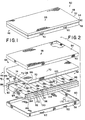
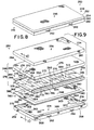
- FIGS. 1-7 A first embodiment of an illustrative mattress structure 50 in accordance with the present invention is shown in FIGS. 1-7 and an illustrative second embodiment of a mattress structure 250 is shown in FIGS. 8-11.
- Illustrative first embodiment of mattress structure 50 in accordance with the present invention includes a mattress cover 52 having a top cover 54 and a bottom cover 58 connected to top cover 54 by a zipper 60.
- Top cover 54 includes an upwardly-facing sleeping surface 56 above which a user will rest.
- Handles 62 can be provided on either top cover 54 or bottom cover 58 as shown in FIG. 1 or on any portion of top or bottom covers 54, 58 as desired to facilitate transport of mattress structure 50.
- Top and bottom covers 54, 58 of mattress cover 52 cooperate to define an interior region 64 of mattress cover 52 as shown in FIG. 2.
- Interior region 64 of mattress cover 52 receives a mattress core 76 including a foam core 66, shear panels 94 carried by foam core 66, and a shear layer 68 as shown in Fig. 2.
- foam core 66 is made from a foam rubber material such as urethane foam, although any suitable material providing similar support and firmness characteristics to those described below for foam core 66 can be used without exceeding the scope of the invention as presently perceived.
- Shear layer 68 includes a top panel 70, downwardly-extending sides 72 appended to the perimeter of top panel 70, and a fitted portion 74 appended to sides 72 and extending at least partially beneath top panel 70.
- Top panel 70 cooperates with sides 72 and fitted portion 74 of shear layer 68 to define an interior region (not shown) which receives foam core 66.
- Fitted portion 74 includes edge 78 defining an opening (not shown) beneath top panel 70 allowing for movement of foam core 66 into and out of the interior region of shear layer 68.
- fitted portion 74 is provided with an elastic band (not shown), a drawstring (not shown), or other structure drawing the opening of fitted portion 74 closed to facilitate wrapping shear layer 68 snugly around foam core 66.
- Mattress structure 50 may be used with a bed or table including an articulating deck (not shown) having pivoting head, shoulder, seat, thigh, or leg sections. As portions of mattress structure 50 bend during articulation of the deck, the movement of mattress structure 50 will cause mattress structure 50 to slide relative to the user resting on sleeping surface 56. If the mattress cover were to slide relative to the user and thus rub against the user during articulation of the deck, this rubbing and sliding could irritate the user's skin.
- Shear layer 68 is preferably made from material having a low coefficient of friction such as nylon or "parachute" material, or any other suitable material that will allow top cover 54 of mattress cover 52 to slide relative to foam core 66. Top cover 54 will frictionally engage the user lying on sleeping surface 56 so that when mattress core 76 includes shear layer 68, top cover 54 will tend to move with the user rather than moving with foam core 66 during articulation of the deck. Thus, use of shear layer 68 will minimize the rubbing of mattress structure 50 against the user during articulation of the deck.
- Foam core 66 includes a generally rectangular foam core frame 80 having an elongated foam first side member 82, an elongated foam second side member 84 spaced apart from first side member 82, a foam end member 86 abutting first and second side members 82, 84 on a head end 46 of foam core 66, and a foam end member 88 abutting first and second side members 82, 84 on a foot end 48 of foam core 66 as shown in Fig. 2.
- Core frame 80 defines a generally rectangular central opening 90 above which the user will rest.
- a plurality of foam columns 92 is received in central opening 90 as shown in Fig. 2 and foam columns 92 are attached to core frame 80.
- Each foam column 92 extends transversely from a first end 96 of foam column 92 abutting first side member 82 to a second end 98 of foam column 92 abutting second side member 84.
- first end 96 of each foam column 92 is attached to first side member 82 and second end 98 of each foam column 92 is attached to second side member 94.
- Each foam column 92 includes first and second spaced-apart side walls 100 as shown best in Figs. 3 and 4. Side walls 100 extend transversely between first and second side members 82, 84 of core frame 80. Side walls 100 also extend generally vertically from a top surface 110 to a bottom surface 112. In addition, each foam column 92 includes a top portion 114 and a bottom portion 116. In preferred embodiments, side walls 100 adjacent to bottom portion 116 of each foam column 92 are attached to bottom portions 116 of adjacent side walls 100 of both adjacent foam columns 92 so that foam core 66 including core frame 80 and foam columns 92 is of unitary construction.
- Top portion 114 of each side wall 100 of each foam column 92 extends downwardly from top surface 110 by a first distance 118 as shown best in Figs. 6 and 7.
- Bottom portion 116 extends upwardly from bottom surface 112 a second distance 120 to meet top portion 114 at an interface 122.
- bottom portion 116 of each side wall 100 is integrally appended to bottom portion 116 of each abutting side wall 100.
- the bottom portions 116 of abutting side walls 100 are joined by R.F.
- any suitable method for joining foam columns 92 such as gluing side walls 100 together, attaching adjacent side walls 100 using plastic rivets or other fastening devices (not shown), or starting with a unitary block of foam and sculpting the block to include a plurality of longitudinally spaced-apart and transversely extending slits defining foam columns therebetween, can be used without exceeding the scope of the invention as presently perceived.
- foam columns 92 define a plurality of zones along foam core 66 which provide support and firmness characteristics for a user carried on sleeping surface 56 of mattress structure 50 as shown in Fig. 4.
- foam columns 92 define a head zone 146 adjacent to head end 46 of foam core 66, a shoulder zone 148 adjacent to head zone 146, a seat zone 150 adjacent to shoulder zone 148, a thigh zone 152 adjacent to seat zone 150, and a foot zone 154 adjacent to thigh zone 152 and foot end 48 of foam core 66.
- Foot zone 154 of illustrative and preferred foam core 66 includes three foam columns 92, each of which include an upper column portion 156 and a lower column portion 158 as shown best in Fig. 4.
- illustrative and preferred frame end members 86, 88 each include an upper end member 160 and a lower end member 162.
- each foam column 92 The firmness and support characteristics provided by each foam column 92 depend in part upon the indention load deflection (ILD) of the foam from which each foam column 92 is made.
- the ILD is a well-known industry-accepted index indicating the "firmness" of materials such as urethane foam and other foam rubber materials.
- the ILD indicates the amount of deflection exhibited by a block of foam when subjected to a specified force distributed over a specified area of foam. It is within the scope of the invention as presently perceived to provide foam core 66 wherein each of the plurality of foam columns 92 has the same ILD or to provide foam core 66 wherein the ILD of at least one foam column 92 is different from the ILD of at least one other foam column 92.
- preferred foam core 66 can be constructed so that foam columns 92 of head zone 146 have an ILD of 11, foam columns 92 of shoulder zone 148 have an ILD of 11, foam columns 92 of seat zone 150 have an ILD of 17, foam columns 92 of thigh zone 152 have an ILD of 11, foot zone 154 lower column portions 158 have an ILD of 11, and foot zone 154 upper column portions 156 have an ILD of 7.
- foam columns 92 be made from foam having ILDs as described above
- foam columns 92 can be made from foam rubber portions of various ILDs to provide the desired support and firmness characteristics for mattress structure 50. For example, it is sometimes desirable to provide foam columns 92 made from foam having an ILD of 17 in shoulder zone 148 to provide additional firmness and support characteristics to mattress structure 50 adjacent to shoulder zone 148.
- Foot zone 154 is provided with upper and lower column portions 156, 158 to relieve interface pressure against the heel of the user while also providing sufficient support for the user's feet. This is achieved by providing upper column portions 156 made from foam having a relatively low ILD and relatively plush support and firmness characteristics, and lower column portions 158 made from foam having a higher ILD to provide additional firmness and support.
- head end and foot end members 86, 88 are each provided with upper and lower end members 160, 162 to achieve a similar result.
- Each upper end member 86 of illustrative and preferred foam core 66 is made from foam having an ILD matching the ILD of the adjacent foam column 92.
- upper end member 160 of head end foam member 86 of illustrative foam core 66 is made from foam having an ILD of 11 just as foam columns 92 of head zone 46 are made from foam having an ILD of 11.
- upper end member 160 of foot end member 88 of illustrative form core 66 is made from foam having an ILD of 7, just as upper column portions 156 of foam columns 92 of foot zone 154 are made from foam having an ILD of 7.
- lower end members 162 are preferably made from urethane foam having an ILD of 41 which provides significantly greater support and firmness characteristics than upper end members 160.
- head end and foot end members 86, 88 from upper end members 160 made from foam having ILDs similar to those of the adjacent foam columns 92 and lower end members 162 providing significantly greater support and firmness characteristics
- head end and foot end members 84, 86 provide support and firmness characteristics to a user lying on sleeping surface 56 that are substantially similar to other portions of sleeping surface 56 while also providing additional support to a user entering or exiting mattress structure 50 from either head end 46 or foot end 48.
- First and second side members 82, 84 include longitudinally extending upper side member 164 and longitudinally extending lower side member 166 as shown in Figs. 1 and 5.
- upper and lower side member 164, 166 of foam core 66 are each made from foam having an ILD of 41 to provide additional support and firmness characteristics along sides of mattress structure 50.
- the additional support and firmness characteristics along sides of mattress structure 50 assist users entering or exiting sleeping surface 56 along the sides of mattress structure 50.
- first and second side members 82, 84 can each be unitary members.
- upper and lower side members 164, 166 of illustrative and preferred core frame 80 of foam core 66 are both made from urethane foam having an ILD of 41, it is within the scope of the invention as is presently perceived to provide upper and lower side members 164, 166 providing different support and firmness characteristics.
- upper side member 164 could be made from foam having an ILD of 17 and lower side member 166 could be made from foam having an ILD of 41 so that side members 82, 84 of core frame 80 provide additional support to users egressing or ingressing onto sleeping surface 56 while also providing a user on sleeping surface with support and firmness characteristics that are similar to the support and firmness characteristics of other portions of sleeping surface 56.
- the foam materials and the firmness and support characteristics resulting therefrom can be varied without exceeding the scope of the invention as presently perceived.
- Each side wall 100 adjacent to top portion 114 of side wall 100 cooperates with top portion 114 of abutting side wall 100 to define a transversely-extending slit 130.
- Side walls 100 of the plurality of foam columns 92 thus cooperate to define a plurality of longitudinally spaced-apart and transversely-extending slits 130 as shown in Figs. 2-4, 6, and 7.
- Each slit 130 has an upper end adjacent to top surface 110 of foam core 66 and a lower end 130 adjacent to interface 122 between top and bottom portions 114, 116.
- each side wall 100 adjacent to bottom portion 116 of side wall 100 cooperates with bottom portion 116 of abutting side wall 100 to define a transversely extending slot 132 beneath slit 130.
- Each slot 132 is associated with a slit 130 which is defined by the same adjacent side walls 100 as slot 132.
- Each slot 132 includes a first end 138 spaced apart from the first end 134 of its associated slit 130 and a second end 140 spaced apart from the second end 136 of its associated slit 130 so that illustrative slots 132 do not extend the full transverse length of slits 130.
- slots 132 are associated with each slit 130 as shown in Fig. 3. Slots 132 are transversely spaced apart from one another and are transversely spaced apart from first side member 82 and second side member 84 of core frame 80. In preferred embodiments, bottom portions 116 of adjacent side walls 100 are attached to one another along portions of bottom portion 116 between slots 132.
- slits 130 extend downwardly from top surface 110 of foam core 66 as shown best in Figs. 6 and 7.
- Slots 132 extend upwardly from bottom surface 112 and cooperate with slits 130 to define openings extending from top surface 110 to bottom surface 112 of foam core 66 as shown best in Fig. 7.
- each foam column 92 can also be formed to include a shallow slit 172 as shown best in Figs. 4, 6, and 7.
- Each shallow slit 172 extends downwardly from top surface 110 to a lower end 174 of shallow slit 172, the lower end 174 being spaced apart from bottom surface 112 a distance 176.
- distance 176 is greater than distance 120 between lower end 142 of slit 130 and bottom surface 112 of foam core 66.
- slit 130 extends downwardly from top surface 110 into foam core 66 a distance greater than shallow slit 172 extends from top surface 110 into foam core 66.
- Shallow slits 172 are formed in foam columns 92 to "fine-tune" the support and firmness characteristics provided by each foam column 92.
- Shallow slits 172 operate to relieve surface tension formed across top surface 110 of each foam column 92.
- Shallow slit 172 relieves surface tension from top surface 110 of foam column 92 and allows foam column 92 to provide columnar support from below instead of "hamocking" and providing sideways support through surface tension in top surface 110.
- support and firmness characteristics provided by each zone 146, 148, 150, 152, 154 of foam core 66 can be altered by making foam columns 92 of each zone 146, 148, 150, 152, 154 from foam having an ILD that is different from the ILD of foam columns 92 of other of zones 146, 148, 150, 152, 154.
- the support and firmness characteristics provided by foam columns 92 can be further adjusted by forming foam columns 92 to include shallow slits 172.
- Illustrative and preferred foam core 66 is formed so that each foam column 92 is formed with a shallow slit 172 and so that a distance 176 between a lower end 174 of shallow slit 172 and bottom surface 112 of foam core 66 is equivalent for each shallow slit 172 within each zone 146, 148, 150, 152, 154.
- distance 176 for shallow slits 172 varies from zone to zone 146, 148, 150, 152, 154.
- distance 176 for shallow slits 172 of seat zone 150 is greater than distance 176 for shallow slits 172 of thigh zone 152.
- the support and firmness characteristics provided by foam columns 92 of seat zone 150 are adjusted slightly by reducing the hamocking effect in seat zone 150, the support and firmness characteristics provided by foam columns 92 of thigh zone 152 are adjusted even further by providing shallow slits 172 that extend deeper into foam core 66 from top surface 110 to provide even further adjustment of thigh zone 152 so that thigh zone 152 provides even softer, plusher support and firmness characteristics than would otherwise be provided.
- Side walls 100 of foam columns 92 are provided with an "anti-friction" shear coating so that each top surface 110 of each foam column 92 can move upwardly and downwardly relative to bottom surface 112 of foam core 66 independently of the upward and downward movement of top surfaces 110 of adjacent foam columns 92 as each foam column 92 compresses and decompresses relative to adjacent foam columns 92.
- Producing foam core 66 without the shear coating on side walls 100 would limit the independent movement of each foam column 92. Instead, each foam column 92 would interact with each adjacent foam column 92 as each side wall 100 frictionally engages each adjacent side wall 100.
- each shear panel 94 includes a generally horizontal top panel 186 having two spaced-apart side edges, a first side panel 184 appended to the first edge of top panel 186 and extending downwardly therefrom, a first tab 182 appended to first side panel 184 and extending downwardly therefrom, a second side panel 188 appended to the second edge of top panel 186 and extending downwardly therefrom, second side panel 188 being spaced apart from first side panel 184, and a second tab 190 appended to second side panel 188 and extending downwardly therefrom.
- First and second side panels 184, 188 are received in slits 130 as shown best in Figs. 5-7 to separate the abutting side walls 100 so that adjacent foam columns 92 are free to compress and decompress without interference due to frictional engagement with side walls 100 of adjacent foam columns 92.
- First and second tabs 182, 190 are received in slots 132 and have exposed ends 192 that extend therethrough as shown best in Figs. 5 and 7.
- exposed end 192 of first tab 182 is attached to exposed end 192 of second tab 190 to connect shear panel 94 to foam core 66.
- shear panel 94 includes joining exposed ends 192 of first and second tabs 182, 190 to hold shear panel 182 to form core 66
- other methods of connecting shear panel 94 to foam core 66 can be employed without exceeding the scope of the invention that is presently perceived.
- first and second side panels 184, 188 can each be directly attached to a side wall 100 of foam columns 192.
- exposed ends 192 of first and second tabs 182, 188 are connected to one another using I-shaped connectors 194 as shown in Figs. 5-7.
- Each I-shaped connector 194 includes an upper bar 196, a lower bar 198, and a connecting post 200 therebetween.
- I-shaped connectors 194 penetrate both exposed ends 192 of first and second tabs 182, 188 so that upper bar 196 is positioned to lie between exposed ends 192 and foam core 66, connecting post 200 is received by openings formed in exposed ends 192 and extends downwardly from upper bar 196 to lower bar 198 which is positioned to lie beneath exposed ends 192 of first and second tabs 182, 190.
- Each shear panel 94 is formed to include openings 210 positioned to lie between longitudinally spaced apart first tabs and additional openings 210 positioned to lie between longitudinally spaced apart second tabs as shown best in Fig. 5.
- Each opening 210 is defined by a downwardly-facing first edge 212 and by side edges 214.
- edge 212 is positioned to lie adjacent to interface 22 and lower end 142 of each slit 130 as shown in Fig. 6.
- shear panel is positioned to lie adjacent to top portion 114 of each side wall 100 that is in abutting engagement with top portion 114 of an adjacent side wall 100 and bottom portion 116 of each side wall 100 that is in abutting engagement with bottom portion 116 of an adjacent side wall 100 while openings 210 of shear panels 94 correspond to portions of foam core 66 at which bottom portions 116 of side walls 100 of abutting foam columns 92 are attached to one another.
- Illustrative shear panels 94 are each wrapped individually around an associated foam column 92 as shown, for example, in Fig. 5 so that mattress core 76 includes a plurality of shear panels 94.
- shear panels 94 connected into a single sheet including a plurality of integrally appended shear panels 94.
- This pattern could be continued having second tabs 190 of the second shear panel 94 connected to first tabs 182 of a third shear panel 94, and so on as desired.
- Shear panels 94 are preferably made from a material having a low coefficient of friction such as nylon or "parachute material.” Although shear panels 94 are preferably made from nylon, any material having a low coefficient friction and that will allow adjacent foam columns 92 to compress and decompress independently of one another can be placed in slits 130 and slots 132 without exceeding the scope of the invention as presently perceived. In addition, it is within the scope of the invention as presently perceived to attach or adhere shear panels 94 to side walls 100 of foam columns 92, to form the shear coating as an additional layer bonded to side walls 100, or to form side walls 100 to include an integral shear coating.
- a material having a low coefficient of friction such as nylon or "parachute material.”
- shear panel 94 thus allows each foam column 92 to compress and decompress independently of each adjacent foam column 92. It is therefore within the scope of the invention as presently perceived to provide an "anti-friction" coating on side walls 100, to provide a shear panel made from nylon or another material having a low coefficient of friction, or to provide a sheet (not shown) of material having a low coefficient of friction including panels that are received by slits 130 and slots 132 so that foam columns 92 can compress and decompress and top surfaces 110 of foam columns 92 can move upwardly and downwardly independent of the position or movement of adjacent top surfaces 110 of abutting foam columns 92.
- the stand alone first embodiment of mattress structure 50 includes mattress core 76 received in interior region 64 of mattress cover 52 as shown in Figs. 2 and 4.
- Mattress cover 52 includes top cover 54 connected to bottom cover 58 by zipper 60 and bottom cover 58 includes foam base 170 which is positioned to lie beneath mattress core 76.
- Mattress structure 50 can be assembled simply by placing foam core 66 and shear layer 68 of mattress core 76 into bottom cover 58, placing top cover 54 over mattress core 76 and shear layer 68, and connecting top cover 54 to bottom cover 58 using zipper 60.
- Mattress core 76 includes foam core 66 carrying shear panels 94 and shear layer 68 which is formed to include an interior region receiving foam core 66 and shear panels 94.
- Foam core 66 is formed to include a plurality of longitudinally spaced-apart foam columns 92.
- Shear panels 94 operate to minimize friction between abutting side walls 100 of foam columns 92 so that each foam column 92 can compress and decompress independently of abutting foam columns 92 and so that top surface 110 of each foam column 92 can move upwardly and downwardly independently of the position of top surfaces 110 of abutting foam columns 92.
- This independent movement of adjacent foam columns provides mattress structure 50 with support and firmness characteristics similar to those provided when mattress structure 50 includes a mattress core 76 having a plurality of longitudinally spaced-apart air bladders instead of foam core 66.
- Mattress structure 50 is compatible with beds having articulating decks on which mattress structure 50 rests so that longitudinally spaced-apart zones of the articulating deck move relative to one another.
- Some conventional mattresses used on articulating decks direct shear forces created during the articulation of the mattress on the deck directly against the user resting on the sleeping surface of the conventional mattress. These shear forces result from the expansion and contraction of the sleeping surface and of the surface of the user engaging the sleeping surface due to the bending and straightening of these surfaces during deck articulation.
- Mattress structure 50 includes shear layer 68 positioned to lie between top cover 54 of mattress cover 52 and foam core 66. Shear layer 68 allows top cover 54 to slide relative to foam core 66. Top cover 54 frictionally engages the user so that top cover 54 will tend to expand and contract with the user and will slide relative to foam core 66, thus minimizing shear forces directed by mattress structure 50 against the user on sleeping surface 56.
- first embodiment of mattress structure 50 can be placed on any generally horizontal upwardly-facing surface upon which a user may rest.
- Second embodiment of mattress structure 250 shown in Figs. 9-11, can also be placed on any generally horizontal, upwardly-facing surface.
- mattress structure 250 includes a mattress core 276 shaped for use with a base 259.
- Mattress structure 250 includes a mattress cover 252 having the top cover 254 and the bottom cover 258 connected to top cover 254 by a zipper 260 as shown in Fig. 8.
- Top cover 254 includes an upwardly-facing sleeping surface 256 above which a user will rest.
- Handles 262 can be provided either on top cover 254 or bottom cover 258 as shown in Figs. 8 and 9 or on any other portion of top or bottom covers 254, 258 as desired to facilitate transport of mattress structure 250.
- Top and bottom covers 254, 258 of mattress cover 252 cooperate to define an interior region 264 of mattress cover 252 as shown in Fig. 9.
- Bottom cover 258 includes base 259 which is formed to include a central opening 261 defining a portion of interior region 264 of mattress cover 252.
- foam core 266 is made from a foam rubber material such as urethane foam, although any suitable material providing similar support and firmness characteristics to those described above for foam core 66 and below for foam core 266 can be used without exceeding the scope of the invention as presently perceived.
- Shear layer 268 includes a top panel 270, downwardly-extending sides 272 appended to the perimeter of top panel 270, and fitted portion 274 appended to the sides 272 and extending at least partially beneath top panel 270.
- Top panel 270 cooperates with sides 272 and fitted portion 274 of shear layer 268 to define an interior region (not shown) which receives foam core 266.
- Fitted portion 274 includes edge 278 defining an opening (not shown) beneath top panel 270 allowing for movement of foam core 266 into and out of the interior region of shear layer 268.
- fitted portion 274 is provided with an elastic band (not shown), a drawstring (not shown), or other structure drawing the opening of fitted portion 274 closed to facilitate wrapping shear layer 268 snugly about foam core 266.
- Foam core 266 includes a generally rectangular foam core frame 280 including an elongated foam first side member 282, an elongated foam second side member 284 spaced-apart from first side member 282, a foam end member 286 abutting first and second side members 282, 284 on a head end 246 of foam core 266, and a foam end member 288 abutting first and second side members, 282, 284 on a foot end 248 of foam core 266 as shown in Fig. 9.
- Core frame 280 defines a generally rectangular central opening 290 above which the user will rest.
- a plurality of foam columns 292 is received in central opening 290 as shown in Figs. 9 and 10 and foam columns 292 are attached to core frame 280, Each foam column 292 extends transversely from the first end 296 of foam column 292 abutting first side member 282 to a second end 298 of foam column 292 abutting second side member 284.
- first end 296 of each foam column 292 is attached to first side member 282 and second end 298 of each foam column 292 is attached to second side member 284.
- Each foam column 292 includes first and second spaced-apart side walls 300 as shown best in Fig. 10.
- Side walls 300 extend transversely between first and second side members 282, 284 of core frame 280.
- Side walls 300 also extend generally vertically from the top surface 310 to a bottom surface 312 and each foam column 292 includes a top portion 314 and a bottom portion 316.
- side walls 300 adjacent to bottom portion 316 of each foam column 292 are attached to bottom portions 316 of adjacent side walls 300 of both adjacent foam columns 292 so that foam core 266 including core frame 280 and foam columns 292 is of unitary construction.
- Top portion 314 of each of side wall 300 of each foam column 292 extends downwardly from top surface 310 by a first distance 318 shown best in Fig. 10.
- Bottom portion 316 extends upwardly from bottom surface 312 a second distance 320 to meet top portion 314 at an interface 322.
- bottom portion 316 of each side wall 300 is attached to bottom portion 316 of each abutting side wall 300.
- the bottom portions 316 of abutting side walls 300 are joined by R.F.
- any suitable method for joining foam columns such as gluing side walls 300 together, attaching adjacent side walls 300 using plastic rivets or other fastening devices (not shown), or starting with a unitary block of foam and sculpting the block to include a plurality of longitudinally spaced-apart and transversely extending slits defining foam columns therebetween can be used without exceeding the scope of the invention as presently perceived.
- foam columns 292 of foam core 266 define a plurality of zones along foam core 266 which provide support and firmness characteristics for a user carried on sleeping surface 256 of mattress structure 250 as shown in Fig. 10.
- foam columns 292 define a head zone 346 adjacent to head end 246 of foam core 266, a shoulder zone 348 adjacent to head zone 346, a seat zone 350 adjacent to shoulder zone 348, a thigh zone 352 adjacent to seat zone 350, and a foot zone 354 adjacent to thigh zone 352 and foot end 248 of foam core 266.
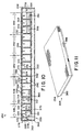
- Foot zone 354 of illustrative and preferred foam core 266 includes three foam columns 292, each of which include an upper column portion 356 and a lower portion 358 as shown best in Fig. 11 so that foot zone 354 can be made from foam rubber materials having different ILDs allowing foam columns 292 on foot zone 254 to relieve interface pressure against the heel of the user while also providing sufficient support for the user's feet.
- Each side wall 300 adjacent to top portion 314 of side wall 300 cooperates with top portion 314 of abutting side wall 300 to define a transversely-extending slit 330.
- Side walls 300 of the plurality of foam columns 292 thus cooperate to define a plurality of longitudinally spaced-apart and transversely-extending slits 330 as shown in Fig. 10.
- each side wall 300 adjacent to bottom portion 316 of side wall 300 cooperates with bottom portion 316 of abutting side wall 300 to define a transversely-extending slot 332 beneath slit 330.
- Each slot 332 is associated with a slit 330 that is defined by the same adjacent side walls 300 as slot 332.
- Each slot 332 of illustrative foam core 266 includes a first end (not shown) spaced-apart from first end 334 of its associated slit 330 and a second end (not shown) spaced-apart from the second end 336 of its associated slit 330 so that illustrative slots 332 do not extend the full transverse distance of slits 330.
- slits 330 of foam core 266 extend downwardly from top surface 310 of foam core 266 as shown best in Fig. 10.
- Slots 332 extend upwardly from bottom surface 312 and cooperate with slits 330 to define openings extending from top surface 310 to bottom surface 312 of foam core 266.
- each foam column 292 can also be formed to include a shallow slit 372 as shown in Fig. 10.
- Each shallow slit 372 extends downwardly from top surface 310 to a lower end 374 of shallow slit 372, lower end 374 being spaced-apart from bottom surface 312 by a distance 376.
- distance 376 is greater than distance 320 between lower end 342 of slit 330 and bottom surface 312 of foam core 266.
- slit 330 extends downwardly from top surface 310 into foam core 266 a distance greater than shallow slit 372 extends from top surface 310 into foam core 266.
- Side walls 300 of foam columns 292 are provided with an anti-friction shear coating so that each top surface 310 of each foam column 292 can move upwardly and downwardly relative to bottom surface 312 of form core 266 independently of the upward and downward movement of top surfaces 310 of adjacent foam columns 292 as each foam column 292 compresses and decompresses relative to adjacent foam columns 292.
- the anti-friction shear coating minimizes the interaction due to frictional engagement of abutting side walls 300, which, in the absence of the shear coating, could significantly reduce the ability of adjacent foam columns 292 to compress and decompress independently of one another, thus reducing the ability of mattress structure 250 to provide support and firmness characteristics similar to those provided by mattress structures having longitudinally spaced apart air bladders.
- the anti-friction shear coating is provided by shear panels 294 of mattress core 276 as shown best in Figs. 9 and 10.
- Shear panels 294 are preferably made from a material having a low coefficient of friction such as nylon or parachute material. Although shear panels 94 are preferably made from nylon, any material having a low coefficient of friction that will minimize the frictional engagement between abutting side walls 100 of adjacent foam columns 292 and allow adjacent foam columns 292 to compress and decompress independently of one another can be placed in slits 330 and slots 332 without exceeding the scope of the invention as presently perceived.
- shear layer 268 is also preferably made from a material having a low coefficient of friction such as nylon, parachute material, or any other suitable material having a low coefficient of friction and that will allow top cover 254 to slide relative to mattress core 276 and foam core 266 during folding or bending movement of portions of mattress structure 250 relative to other portions of mattress structure 250.
- a material having a low coefficient of friction such as nylon, parachute material, or any other suitable material having a low coefficient of friction and that will allow top cover 254 to slide relative to mattress core 276 and foam core 266 during folding or bending movement of portions of mattress structure 250 relative to other portions of mattress structure 250.
- top cover 254 and bottom cover 258 cooperate to define interior region 264 of mattress cover 252 as shown in Figs. 9 and 10.
- bottom cover 258 covers base 259 that defines central opening 261 which comprises a portion of interior region 264.
- Base 259 includes a generally horizontal foam base 370 surrounded by base frame 368.
- Base frame 368 includes a head end member 362, a foot end member 364 longitudinally spaced-apart from head end member 362, and transversely spaced-apart side members 366 attached to each of the head and foot end members 362, 364 as shown in Fig. 9.
- each of end members 362, 364 and side members 366 are integrally appended to foam base 370 as shown in Fig. 10 and each includes a side surface cooperating with side surfaces of each other member 362, 364, 366 to define an inwardly-directed side surface 369 of base frame 368.
- Foam base 370 includes a top surface 374, and top surfaces of side members 366 and end members 362, 364 cooperate to define a generally planer top surface 376 of base frame 368.
- Illustrative foam base 370 is preferably made from relatively stiff foam rubber such as, for example, foam rubber having an ILD of 44, and end members 362, 364 and side members 366 are likewise preferably made from foam rubber having an ILD of 44 to provide mattress structure 250 with relatively firm firmness and support characteristics around the perimeter of mattress structure 250.
- Providing mattress structure 250 including base frame 370 having relatively firm firmness and support characteristics around the perimeter of mattress structure 250 will assist the user when entering or exiting sleeping surface 256 of mattress structure 250.
- Members 282, 284, 286, 288 of core frame 280 preferably extend downwardly from top surface 310 of foam core 266 by distance 318 to bottom surfaces adjacent to interface 322 as shown in Fig. 10 so that the bottom surfaces of members 282, 284, 286, 288 of core frame 280 cooperate to define a generally planer downwardly-facing bottom surface 378 of core frame 280 as shown in Figs. 9 and 10.
- bottom surface 378 of core frame 280 engages top surface 376 of base frame 368.
- bottom surface 312 of foam core 266 engages top surface 374 of foam base 370.
- base 259 includes base frame 368 having side members 366 and end members 362, 364 that extend upwardly from top surface 374 of foam base 370 and include inwardly-facing side surfaces 369 engaging mattress core 276 to prevent mattress core 276 from moving longitudinally or laterally relative to base 259.
- mattress core 276 is configured to conformingly nest in base 259.
- base 259 and mattress core 276 provide some of the advantages of a step deck and mattress as described in U.S. Patent Application Serial Nos. 08/511,546 to Kramer et al. and 08/511,547 to Weismiller et al., both filed on August 4, 1995, the specifications of which are herein incorporated by reference.
- Mattress structure 250 also includes a storage cover bottom 382 as shown in Figs. 9 and 11.
- Storage cover bottom 382 is not part of mattress core 276 and is not received in interior region 264 of mattress cover 252. Instead, storage cover bottom 382 cooperates with top cover 254 of mattress cover 252 to define a storage cover 384 for protecting mattress core 276 during storage of mattress core 276.
- Storage cover bottom 382 includes a perimetral zipper 386 that engages zipper 260 on top cover 254 to attach storage cover bottom 382 to top cover 254.
- Storage cover bottom 382 and top cover 254 cooperate to define an interior region of storage cover 384 receiving mattress core 276 as shown in Fig. 9.
- Storage cover bottom 382 includes a bottom panel 388 having a generally rectangular perimetral edge 394, sides 390 extending upwardly from perimetral edge 394, and a generally horizontal flange 392 extending outwardly from sides 390.
- Flange 392 includes a generally rectangular outer perimetral edge and zipper 386 is attached to the edge of flange 392 as shown in Fig. 9.
- Bottom panel 388 and sides 390 of storage cover bottom 382 cooperate to define storage space 384 receiving mattress core 276 as shown in Fig. 9.
- mattress core 276 and storage cover bottom 382 are configured so that bottom surface 378 of core frame 280 engages flange and bottom surface 312 of foam core 266 engages bottom panel 388 of storage cover bottom 382 when foam core 266 is received in storage cover 384.
Landscapes
- Health & Medical Sciences (AREA)
- Nursing (AREA)
- Life Sciences & Earth Sciences (AREA)
- Animal Behavior & Ethology (AREA)
- General Health & Medical Sciences (AREA)
- Public Health (AREA)
- Veterinary Medicine (AREA)
- Mattresses And Other Support Structures For Chairs And Beds (AREA)
- Thermotherapy And Cooling Therapy Devices (AREA)
Claims (34)
- Länglicher Matratzenkern (76; 276) für eine Matratzenstruktur (50; 250), wobei der Matratzenkern umfasst:wobei jedes benachbarte Paar von Schlitzen (130; 330) eine Schaumstoffsäule (92; 292) bildet, so dass der Schaumstoffkern (66; 266) eine Vielzahl von in Längsrichtung im Abstand befindlichen und sich quer erstreckenden Schaumstoffsäulen (92; 292) hat, wobei jede Schaumstoffsäule ein Paar allgemein senkrechte Säulenseitenwände (100; 300) hat, welche die Schlitze (130; 330) bilden, dadurch gekennzeichnet, dass jede Säulenseitenwand (100; 300) einen Anti-Scherüberzug (94; 294) einschließt, der einen niedrigen Reibungskoeffizienten hat, damit sich jede Säule (92; 292) komprimieren und dekomprimieren kann, ohne dass Zugkräfte, die sich aus der reibenden Verbindung mit den benachbarten Seitenwänden (100; 300) ergeben, das Komprimieren und Dekomprimieren beeinflussen können.einen Schaumstoffkern (66; 266) einschließlicheiner nach oben gerichteten Oberseite (110; 310),eine Unterseite (112; 312), die sich im Abstand zur Oberseite befindet, und erste und zweite längliche Seiten, welche die Oberseite (110; 319) und Unterseite (112; 312) verbinden, wobei der Schaumstoffkern (66; 266) so geformt ist, dass er eine Vielzahl von in Längsrichtung im Abstand zueinander angeordneten quer verlaufenden Schlitzen (130; 330) enthält, die sich von der Oberseite (110; 310) nach unten erstrecken, jeder Schlitz (130; 330) an einem unteren Ende (142; 342) endet, das sich durch einen ersten Abstand (118; 318) im Abstand zur der Unterseite (112; 312) befindet und sich quer von einem ersten Schlitzende (96), das im Abstand zur ersten Seite des Schaumstoffkerns (66; 266) angeordnet ist, zu einem zweiten Schlitzende (98) erstreckt, das sich im Abstand zur zweiten Seite des Schaumstoffkerns befindet,
- Matratzenkern (76; 276) nach Anspruch 1, worin der Anti-Scherüberzug (94; 294) ein Material einschließt, das einen niedrigen Reibungskoeffizienten hat, der von mindestens einem Schlitz (130: 330) aus der Vielzahl der Schlitze aufgenommen wird.
- Matratzenkern (76; 276) nach Anspruch 1 oder Anspruch 2, worin mindestens eine Schaumstoffsäule (92; 292) so geformt ist, dass sie einen flachen zweiten Schlitz (172; 372) einschließt, der sich von der Oberseite (110; 310) nach unten erstreckt und in einem unteren Ende (174; 374) endet, das sich durch einen zweiten Abstand (176; 376) im Abstand zur Unterseite (112; 312) befindet und sich quer von einem ersten flachen Schlitzende, das im Abstand zur ersten Seite des Schaumstoffkerns (66; 266) angeordnet ist, zu einem zweiten Schlitzende erstreckt, das sich im Abstand zur zweiten Seite des Kerns (66; 266) befindet, wobei der zweite Abstand (176; 376) größer als der erste Abstand (118; 318) ist.
- Matratzenkern nach Anspruch 1 oder Anspruch 2, worin die Vielzahl der Schaumstoffsäulen (92; 292) eine erste Schaumstoffsäule, die aus einem Schaumgummi hergestellt ist, der eine erste Einbeulung unter Einwirkung von Last hat, und eine zweite Schaumstoffsäule einschließt, die aus einem Schaumgummi hergestellt ist, der eine zweite Einbeulung unter Einwirkung von Last hat, wobei sich die zweite Einbeulung unter Einwirkung von Last von der ersten Einbeulung unter Einwirkung von Last unterscheidet.
- Matratzenkern nach Anspruch 4, worin die Oberseite (110; 310) der ersten Säule so geformt ist, dass sie einen quer verlaufenden Einschnitt (172; 372) einschließt, der sich von der Oberseite (110: 310) nach unten erstreckt, so dass die sich die Trag- und Festigkeitseigenschaften der Matratze neben der ersten Säule von den Trag- und Festigkeitseigenschaften unterscheiden, welche durch die erste Säule gegeben wurden, bevor der quer verlaufenden Einschnitt (172; 372) gebildet wird.
- Matratzenkern nach einem der vorstehenden Ansprüche, worin der Schaumstoffkern (66; 266) so gebildet ist, dass er eine Vielzahl von Spalten (132; 332) einschließt, wobei jeder Spalt mit einem Schlitz (130; 330) verbunden ist und sich von der Unterseite (112; 312) allgemein senkrecht nach oben zu dem unteren Ende des mit ihm verbundenen Schlitzes erstreckt, so dass die Spalte (132; 332) mit dem Schlitz (130; 330) zusammenwirkt, um eine Öffnung zu bilden, die sich von der Oberseite (110; 310) durch den Schaumstoffkern (66; 266) zur Unterseite (112; 312) erstreckt, wobei sich jeder Spalt quer von einem ersten Spalt erstreckt und sich im Abstand zur ersten Seite des Kerns und einem zweiten Spaltende befindet, das sich im Abstand zur zweiten Seite des Kerns befindet.
- Matratzenkern nach Anspruch 6, worin der Abstand zwischen dem ersten und zweiten Schlitzende größer ist als der Abstand zwischen dem ersten und zweiten Spaltende.
- Matratzenkern nach Anspruch 6 oder Anspruch 7, worin sich der erste Spalt im Abstand zum ersten Schlitzende und der zweite Spalt im Abstand zum zweiten Schlitzende befindet.
- Matratzenkern nach einem der Ansprüche 6 bis 8, worin eine Vielzahl von Spalten (132; 332) mit jedem Schlitz (130; 330) verbunden ist.
- Matratzenkern nach Anspruch 9, worin die Vielzahl der Spalte (32; 332), die mit jedem Schlitz (130; 330) verbunden ist, drei Spalten einschließt.
- Matratzenkern nach einem der Ansprüche 6 bis 10, worin der Anti-Scherüberzug (94) so geformt ist, dass er ein Endstück (182; 190) einschließt, das von dem Spalt (132) aufgenommen wird, so dass sich der Anti-Scherüberzug von der Oberseite (110) des Schaumstoffkerns (66) bis zur Unterseite (112) des Schaumstoffkerns erstreckt.
- Matratzenkern nach einem der vorstehenden Ansprüche, worin der Schaumstoffkern (66; 266) einen Rahmen (80; 280) einschließt, der ein längliches erstes Schaumstoffseitenteil (82; 282) einschließt, das eine Innenseite und eine Außenseite hat, die sich im Abstand zur Innenseite befindet und die erste Seite des Schaumstoffkerns bildet, und ein längliches zweites Schaumstoffseitenteil (84; 284) einschließt, das eine Innenseite und eine Außenseite hat, die sich im Abstand zur Innenseite befindet und die zweite Seite des Schaumstoffkerns bildet, wobei sich die Schlitze (130; 330) von der Innenseite des ersten Schaumstoffseitenteils (82; 282) zur Innenseite des zweiten Schaumstoffseitenteils (84; 284) erstrecken.
- Matratzenkern nach Anspruch 12, worin der Rahmen (80; 280) erste und zweite Schaumstoffendstücke (86; 88; 286; 288) einschließt, wobei jedes Schaumstoffendstück sowohl an das erste als auch zweite Schaumstoffseitenteil (82; 84; 282; 284) stößt und jedes Schaumstoffendstück eine Schaumstoffsäule (92; 292) einschließt.
- Matratzenkern nach Anspruch 13, worin die ersten und zweiten Schaumstoffendstücke (86; 88; 286; 288) und die ersten und zweiten Schaumstoffseitenteile (82; 84; 282; 284) jeweils eine Einbeulung unter Einwirkung von Last haben, die größer als die Einbeulung unter Einwirkung von Last der Vielzahl der Schaumstoffsäumen (92; 292) ist, so dass die Matratzenstruktur entlang dem Umfang der Matratze größere Festigkeit und Tragvermögen hat.
- Matratzenkern nach einem der Ansprüche 12 bis 14, worin jedes Seitenteil (82; 84) ein oberes Schaumstoffseitenteil (164) einschließt, das an mindestens einer Schaumstoffsäule aus der Vielzahl der Schaumstoffsäulen (92) gefestigt ist, und ein unteres Schaumstoffseitenteil (166) unter dem oberen Schaumstoffseitenteil (164) positioniert und an mindestens einer Schaumstoffsäule der Vielzahl von Schaumstoffsäulen (92) befestigt ist.
- Matratzenkern nach einem der vorstehenden Ansprüche, worin der Schaumstoffkern (66) in Längsrichtung im Abstand zueinander angeordnete Kopf- (146; 346), Schulter- (148; 348), Sitz-(150; 350), Oberschenkel- (152; 352) und Fußzonen (154; 354) einschließt, wobei jede Zone mindestens eine Schaumstoffsäule (92; 292) einschließt, wobei die Schaumstoffsäulen jeder Zone aus Schaumstoff hergestellt sind, der eine ausgewählte Einbeulung unter Einwirkung von Last hat, die Einbeulung unter Einwirkung von Last in jeder Zone für jede Zone unabhängig von den anderen Zonen einzeln wählbar ist.
- Matratzenkern nach Anspruch 16, worin eine Schaumstoffsäule der Fußzone (154; 354) einen oberen Säulenteil (156; 356), der eine ausgewählte erste Einbeulung unter Einwirkung von Last hat, und eine, unteren Säulenteil (158; 358) unter dem oberen Säulenteil einschließt, der eine zweite Einbeulung unter Einwirkung von Last hat, die größer ist als die erste Einbeulung unter Einwirkung von Last, so dass der untere Säulenteil (158; 358) fester als der obere Säulenteil (156; 356) ist und die Matratzenstruktur neben der Fußzone (154; 354) im allgemeinen ähnliche Tragund Festigkeitseigenschaften aufweist wie die Matratzenstruktur neben den Kopf- (146; 346), Schulter- (148; 348), Sitz- (150; 350) und Oberschenkelzonen (152; 352) und dabei gleichzeitig den Druck an den Schnittstellen neben den Fersen des Benutzers reduziert.
- Matratzenkern nach Anspruch 16 oder Anspruch 17, worin eine Schaumstoffsäule jeweils der Kopf- (146; 346), Schulter- (148; 348) und Oberschenkelzonen (152; 352) aus Schaumstoff hergestellt ist, der eine erste ausgewählte Einbeulung unter Einwirkung von Last hat, und eine Schaumstoffsäule des Sitzabschnitts (150; 350) aus Schaumstoff hergestellt ist, der eine zweite gewählte Einbeulung unter Einwirkung von Last, die größer ist als die erste Einbeulung unter Einwirkung von Last, so dass die Aufnahme- und Festigkeitseigenschaften der Matratzenstruktur neben der Sitzzone (150; 350) größer sind als die Aufnahme- und Festigkeitseigenschaften der Matratzenstruktur neben den Kopf- (146; 346), Schulter- (148; 348) und Oberschenkelzonen (152; 352).
- Matratzenkern nach einem der Ansprüche 16 bis 18, wenn abhängig von Anspruch 3, worin der zweite Abstand (176; 376) jedes flachen Schlitzes (172; 372) innerhalb jeder Zone allgemein gleich dem zweiten Abstand jedes anderen flachen Schlitzes innerhalb der Zone ist, der zweite Abstand (176; 376) in einer der Kopf- (146; 346), Schulter- (148; 348), Sitz- (150; 350), Oberschenkel- (152; 352) und Fußzonen (154; 354) sich von dem zweiten Abstand in einer anderen Kopf-, Schulter-, Sitz-, Oberschenkel- und Fußzone unterscheidet.
- Matratzenkern nach einem der Ansprüche 6 bis 10, worin jede Schaumstoffsäule (92; 292) einen oberen Teil (114; 314) und einen unteren Teil (116; 316) unterhalb des Oberteils einschließt, die Seitenwände (100; 300) jeder Schaumstoffsäule neben dem Oberteil (114; 314) jeden betreffenden Schlitz (130; 330), die Seitenwände (100; 300) jeder Schaumstoffsäule (92; 292) neben dem unteren Teil (116; 316) jedes betreffende Spalts (132; 332) bilden, und der untere Teil jeder Schaumstoffsäule an dem unteren Teil jeder benachbarten Schaumstoffsäule befestigt ist, damit der Schaumstoffkern eine einheitliche Konstruktion hat.
- Matratzenkern nach Anspruch 20, worin der Anti-Scherüberzug (94) ein erstes Endstück (182), eine an dem ersten Endstück befestigte Seitenbahn (184), eine an der ersten Seitenbahn befestigte obere Bahn (186), eine an der oberen Bahn befestigte zweite Seitenbahn (188) und ein zweites an der zweiten Seitenbahn befestigtes Endstück (190) einschließt, wobei der Anti-Scherüberzug (94) eine Schaumstoffsäule der Vielzahl von Schaumstoffsäulen (92) umhüllt, so dass die obere Bahn (186) die Oberseite (110) einschließt, die erste (184) und zweite (188) Seitenbahn die erste und zweite Seitenwand (100) einschließen, das erste Endstück (182) von dem Spalt (132) aufgenommen wird, der durch die erste Seitenwand (100) gebildet wird und sich durch diese erstreckt, und das zweite Endstück (190) von dem Spalt (132) aufgenommen wird, der durch die zweite Seitenwand (100) gebildet wird und sich durch diese erstreckt.
- Matratzenkern nach Anspruch 21, worin das erste Endstück (182) an dem zweiten Endstück (190) befestigt ist, um den Anti-Scherüberzug (94) auf der Schaumstoffsäule (92) zu halten.
- Matratzenkern nach Anspruch 22, worin ein I-förmiges Verbindungsteil (194) durch das erste und zweite Endstück (182; 190) hindurchgeht, um das erste Endstück an dem zweiten Endstück zu befestigen.
- Matratzenkern nach einem der Ansprüche 21 bis 23, worin der Anti-Scherüberzug (94) eine einheitlich längliche Bahn ist, die eine Vielzahl von Endstücken (182; 190), eine Vielzahl von Seitenbahnen (194; 188) und eine Vielzahl von oberen Bahnen (186) einschließt, jeder Spalt (132) einen Teil des Materials aufnimmt, das einen niedrigen Reibungskoeffizienten hat, damit jede Schaumstoffsäule (92; 292) unabhängig von jeder anderen Schaumstoffsäule komprimiert und dekomprimiert werden kann.
- Matratzenkern nach Anspruch 24, worin drei im Abstand zueinander quer angeordnete erste Endstücke (182) an der ersten Seitenbahn (184) des Anti-Scherüberzugs (94) befestigt sind und drei im Abstand zueinander quer angeordnete zweite Endstücke (190) an der zweiten Seitenbahn (188) des Anti-Scherüberzugs (94) befestigt sind.
- Matratzenkern nach einem der vorstehenden Ansprüche, worin der Schaumstoffkern (66; 266) eine einheitliche Konstruktion hat.
- Matratzenstruktur umfassend den Matratzenkern nach einem der vorstehenden Ansprüche, eine Matratzenabdeckung (52, 252) mit einem Oberteil (54; 254) und einem Unterteil (58; 258) und die einen inneren Bereich (64; 264) bilden, der den Matratzenkern aufnimmt, wobei der Oberteil und der Unterteil der Matratzenabdeckung separate Teile sind, die miteinander verbunden werden, um den Innenbereich zu bilden, und eine Scherschicht (68; 268), die aus einem Material hergestellt ist, das einen niedrigen Reibungskoeffizienten hat, wobei Scherschicht so angeordnet ist, dass sie zwischen dem Matratzenkern und der oberen Matratzenabdeckung (54; 254) liegt, damit sich die Matratzenabdeckung (52; 252) in Bezug auf den Matratzenkern verschieben kann.
- Matratzenstruktur umfassend den Matratzenkern nach einem der Ansprüche 1 bis 26, eine Matratzenabdeckung (52, 252) mit einem Oberteil (54; 254) und einem Unterteil (58; 258) und die einen Innenbereich (64; 264) bilden, der den Matratzenkern aufnimmt, und eine Scherschicht (68; 268), die aus einem Material hergestellt ist, das einen niedrigen Reibungskoeffizienten hat, wobei die Scherschicht so angeordnet ist, dass sie zwischen dem Matratzenkern und der Oberseite (54; 254) der oberen Matratzenabdeckung (52; 252) liegt, damit sich die Matratzenabdeckung in Bezug auf den Matratzenkern verschieben kann, wobei die Scherschicht (68; 268) ein einheitliches Element ist, das eine obere Bahn (70; 270), welche die Oberseite (110; 310) des Schaumstoffkerns (66; 266) einschließt und abdeckt, sich nach unten erstreckende Seiten (72; 272), die an der oberen Bahn angefügt sind und die Seiten des Schaumstoffkerns (66; 266) einschließen und abdecken, und einen zugeschnittenen Teil (74; 274) hat, der die Unterseite (112; 312) des Schaumstoffkerns einschließt.
- Matratzenstruktur nach Anspruch 27 oder Anspruch 28, worin die Scherschicht (68; 268) den Matratzenkern umgibt.
- Matratzenstruktur umfassendein Grundelement (259) einschließlich eines um dessen Umfang verlaufenden rechteckigen Grundrahmens (368) mit einer Oberseite (376) und der eine zentrale Öffnung (261) darin bildet, und eines Schaumstoffbodens (370), der an dem Grundrahmen befestigt ist und eine Oberseite (374) hat, die sich im Abstand zu einer Ebene und unterhalb dieser Ebene befindet, die durch die Oberseite (376) des Rahmens (368) gebildet wird, um einen Raum zu bilden, der den Kern aufnimmt, undden Matratzenkern nach einem der Ansprüche 12 bis 15, wobei der Matratzenkern (66; 266) von dem Grundelement (259) getragen wird, so dass eine Bodenseite (112; 312) des Kernrahmens (80; 280) an der Oberseite (374) des Grundrahmens (368) anliegt und die Unterseiten der Schaumstoffsäulen (92; 292) von dem den Kern aufnehmenden Raum aufgenommen werden.
- Matratzenstruktur nach Anspruch 30, worin die Unterseiten der Schaumstoffsäulen (92; 292) an der Oberseite des Bodens (370) des Grundelements (239) anliegen.
- Matratzenstruktur nach Anspruch 30 oder Anspruch 31, ferner umfassend eine Matratzenabdeckung (252) mit einem Oberteil (256) und einem Innenbereich (264), der das Grundelement (259) aufnimmt, den Schaumstoffkern (266), und eine Scherschicht (268), die aus einem Material hergestellt ist, das einen niedrigen Reibungskoeffizienten hat und so angeordnet ist, das es zwischen dem Schaumstoffkern (266) und dem Oberteil (256) der Matratzenabdeckung (252) liegt, damit sich die Matratzenabdeckung in Bezug auf den Schaumstoffkern verschieben kann.
- Matratzenstruktur nach Anspruch 32, worin die Matratzenabdeckung (252) eine obere Abdeckung (254), die den Schaumstoffkern (266) abdeckt, und eine untere Abdeckung (258), die das Grundelement (259) abdeckt und durch einen Reißverschluss (260), der um den Umfang des Grundrahmens (368) angeordnet ist, mit der oberen Abdeckung (254) verbunden ist.
- Matratzenstruktur nach Anspruch 33, ferner umfassend eine Abdeckung zur Aufbewahrung (384), die mit der oberen Abdeckung (254) zusammenwirkt, um einen Raum zur Aufbewahrung zu bilden, der den Schaumstoffkern (266) aufnimmt, wobei die Abdeckung zur Aufbewahrung (384) durch einen Reißverschluss (260, 368), der um den Umfang des Kernrahmens (266) angeordnet ist, mit der oberen Abdeckung (254) verbunden ist.
Applications Claiming Priority (3)
| Application Number | Priority Date | Filing Date | Title |
|---|---|---|---|
| US653416 | 1996-05-24 | ||
| US08/653,416 US5802646A (en) | 1995-11-30 | 1996-05-24 | Mattress structure having a foam mattress core |
| PCT/US1997/008711 WO1997043927A1 (en) | 1996-05-24 | 1997-05-16 | Mattress structure having a foam mattress core |
Publications (3)
| Publication Number | Publication Date |
|---|---|
| EP0955848A1 EP0955848A1 (de) | 1999-11-17 |
| EP0955848A4 EP0955848A4 (de) | 2002-06-12 |
| EP0955848B1 true EP0955848B1 (de) | 2005-04-13 |
Family
ID=24620799
Family Applications (1)
| Application Number | Title | Priority Date | Filing Date |
|---|---|---|---|
| EP97927710A Expired - Lifetime EP0955848B1 (de) | 1996-05-24 | 1997-05-16 | Matrazze mit einem schaumstoffkern |
Country Status (9)
| Country | Link |
|---|---|
| US (2) | US5802646A (de) |
| EP (1) | EP0955848B1 (de) |
| JP (1) | JP2000511086A (de) |
| AT (1) | ATE292922T1 (de) |
| AU (1) | AU3210497A (de) |
| BR (1) | BR9709114A (de) |
| CA (1) | CA2255616A1 (de) |
| DE (1) | DE69733034T2 (de) |
| WO (1) | WO1997043927A1 (de) |
Families Citing this family (61)
| Publication number | Priority date | Publication date | Assignee | Title |
|---|---|---|---|---|
| US6115861A (en) * | 1997-10-09 | 2000-09-12 | Patmark Company, Inc. | Mattress structure |
| DE69829073T2 (de) | 1997-12-11 | 2005-06-30 | Hill-Rom Services, Inc., Batesville | Matratzenstruktur |
| JP2002509745A (ja) | 1998-03-31 | 2002-04-02 | ヒル−ロム,インコーポレイティド | エアオーバフォームマットレス |
| US9462893B2 (en) | 1998-05-06 | 2016-10-11 | Hill-Rom Services, Inc. | Cover system for a patient support surface |
| US7191482B2 (en) | 1998-05-06 | 2007-03-20 | Hill Rom Services, Inc. | Patient support |
| AU3972599A (en) | 1998-05-06 | 1999-11-23 | Hill-Rom, Inc. | Mattress or cushion structure |
| US6286166B1 (en) | 1998-06-19 | 2001-09-11 | Hill-Rom Services, Inc. | Modular foam mattress |
| ATE262821T1 (de) | 1998-12-11 | 2004-04-15 | Hill Rom Services Inc | Seitenpolstersystem für eine matratze |
| US6427264B1 (en) | 1999-03-19 | 2002-08-06 | Hill-Rom Services, Inc. | Gap filler for bed |
| US6282735B1 (en) * | 1999-08-23 | 2001-09-04 | Hill-Rom Services, Inc. | Hydrotherapy bed |
| US6516483B1 (en) | 2000-03-28 | 2003-02-11 | The Or Group, Inc. | Patient support surface |
| DK2140847T3 (da) | 2000-11-07 | 2012-08-27 | Tempur World Llc | Terapeutisk madrasanordning |
| CA2435736A1 (en) | 2001-02-15 | 2002-08-29 | Hill-Rom Services, Inc. | Self-inflating mattress |
| WO2003005859A2 (en) * | 2001-07-11 | 2003-01-23 | Alfmeier Corporation | Integrated adjustable lumbar support and trim attachment system |
| US6855158B2 (en) | 2001-09-11 | 2005-02-15 | Hill-Rom Services, Inc. | Thermo-regulating patient support structure |
| US6839929B2 (en) | 2001-12-13 | 2005-01-11 | Hill-Rom Services, Inc. | Self-sealing mattress structure |
| US6668399B2 (en) | 2002-02-01 | 2003-12-30 | Kci Licensing, Inc. | Bolster system for a patient support surface |
| ATE337718T1 (de) * | 2002-04-12 | 2006-09-15 | Dreamwell Ltd | Kassetten bettsystem |
| US6829795B2 (en) * | 2002-10-04 | 2004-12-14 | Woodbridge Foam Corporation | Covered foam article |
| US6968585B2 (en) * | 2003-09-22 | 2005-11-29 | Mark Shaw | Antidecubitus heel pad |
| US7293311B2 (en) | 2004-03-04 | 2007-11-13 | Spring Air West, L.L.C. | Method of making a multilayered mattress component |
| US7326664B2 (en) * | 2004-03-05 | 2008-02-05 | Polymergroup, Inc. | Structurally stable flame retardant bedding articles |
| EP1847200B1 (de) * | 2004-06-04 | 2009-07-22 | Hill-Rom Services, Inc. | Matratze mit Fersendruckentlastungsteil |
| EP1829517B9 (de) * | 2004-08-23 | 2012-09-19 | Matthias Gondorf | Verfahren zur Reinigung einer Matratze |
| US7779496B2 (en) * | 2004-12-02 | 2010-08-24 | Joerns Llc | Air mattress for bed with step deck |
| US20080155755A1 (en) * | 2004-12-02 | 2008-07-03 | Scott Technology Llc | Mattress for bed with step deck and bed therewith |
| AT501543B1 (de) * | 2005-02-22 | 2006-12-15 | Das Gesundheitshaus Gesmbh & C | Gliederelement-matte |
| ATE526199T1 (de) | 2005-04-08 | 2011-10-15 | Alfmeier Praez Ag | Fahrzeugsitz mit lordosenstütze |
| US7469437B2 (en) | 2005-06-24 | 2008-12-30 | Tempur-Pedic Management, Inc. | Reticulated material body support and method |
| US8104122B2 (en) | 2005-12-19 | 2012-01-31 | Hill-Rom Services, Inc. | Patient support having an extendable foot section |
| EP1983865B1 (de) | 2006-02-08 | 2015-03-25 | Hill-Rom Services, Inc. | Endplatte für patientenauflagevorrichtung |
| CA2922187C (en) * | 2006-05-05 | 2020-06-02 | Nubatech Inc. | Cushioning structures for body parts |
| US8011045B2 (en) | 2006-06-12 | 2011-09-06 | Allen Medical Systems, Inc. | Localized patient support |
| NL1032313C2 (nl) * | 2006-08-14 | 2008-06-03 | Joost Groenen | Modulair matras met segmenten. |
| US8006333B2 (en) * | 2006-11-16 | 2011-08-30 | Stryker Corporation | Patient support surface with turn-assist |
| US8117700B2 (en) | 2007-02-26 | 2012-02-21 | Howard John Hunter | Mattress system and method |
| US7712171B2 (en) * | 2007-04-25 | 2010-05-11 | Hill-Rom Services, Inc. | Patient support including turn assist, low air loss, or integrated lateral transfer |
| US20090064605A1 (en) * | 2007-09-07 | 2009-03-12 | Hoffman David J | Dock seal with partially sliced foam core |
| WO2010051303A1 (en) | 2008-10-28 | 2010-05-06 | Allen Medical Systems, Inc. | Prone and laterally angled surgical device and method |
| US20100281618A1 (en) * | 2009-05-08 | 2010-11-11 | Span-America Medical Systems, Inc. | Internal structural configurations of bladders used in patient support systems |
| NL1037080C2 (nl) * | 2009-06-26 | 2010-12-28 | Norma Boxmeer Bv | Pocketverenmatras met ligvlakken. |
| CN102481057B (zh) * | 2009-07-29 | 2015-01-21 | 意大利凝胶技术有限公司 | 模块式支承元件 |
| US8621694B2 (en) * | 2009-09-12 | 2014-01-07 | Fxi, Inc. | Sleep support surface that includes a layer with large diameter cleaving |
| US8438682B2 (en) | 2009-12-09 | 2013-05-14 | Span-America Medical Systems, Inc. | Shear reducing mattress cover |
| US20110145996A1 (en) * | 2009-12-22 | 2011-06-23 | Kara Johan | Reversible Foam Mattress and Method of Construction |
| USD712682S1 (en) * | 2010-07-30 | 2014-09-09 | Dreamwell, Ltd. | Mattress border |
| US8341778B2 (en) | 2011-02-07 | 2013-01-01 | Hill-Rom Services, Inc. | Bed gap filler and footboard pad |
| DE202011051235U1 (de) * | 2011-09-08 | 2012-12-10 | Wilfried Scholz | Matratze |
| US9295599B2 (en) * | 2011-09-30 | 2016-03-29 | Offloading Technologies, Inc. | Methods and systems for a dynamic support mattress to treat and reduce the incidence of pressure ulcers |
| US9861208B2 (en) | 2013-06-07 | 2018-01-09 | Mattress Development Company Of Delaware, Llc | Multifunctional mattress systems |
| USD738644S1 (en) | 2013-09-20 | 2015-09-15 | Future Foam, Inc. | Pillow |
| US10709256B2 (en) * | 2015-12-12 | 2020-07-14 | Level Sleep Llc | Efficient mattress having low pressure and alignment |
| US9504620B2 (en) | 2014-07-23 | 2016-11-29 | American Sterilizer Company | Method of controlling a pressurized mattress system for a support structure |
| US10426680B2 (en) | 2015-07-31 | 2019-10-01 | Hill-Rom Services, Inc. | Air bladder control of mattress/frame width expansion |
| SG10201607758TA (en) * | 2016-08-05 | 2018-03-28 | Pt Massindo Int | Mattress with adjustable hardness and comfort levels |
| EP3476380B1 (de) | 2017-10-24 | 2020-05-13 | Hill-Rom Services, Inc. | Modulare drehassistenzvorrichtung und verfahren dafür |
| EP3530251A3 (de) | 2018-02-27 | 2019-10-30 | Hill-Rom Services, Inc. | Patientenlagerung |
| WO2020174418A1 (en) | 2019-02-26 | 2020-09-03 | Hill-Rom Services, Inc. | Patient positioning apparatus and mattress |
| US20220369823A1 (en) * | 2021-05-21 | 2022-11-24 | Dreamwell, Ltd. | Contiguous mattress system for adjustable base foundation |
| US12446140B2 (en) | 2022-01-05 | 2025-10-14 | Carico International, Llc | Grounded mattress |
| US20240156277A1 (en) * | 2022-11-10 | 2024-05-16 | Ted Lazakis | Interchangable modular mattress |
Family Cites Families (79)
| Publication number | Priority date | Publication date | Assignee | Title |
|---|---|---|---|---|
| US595734A (en) * | 1897-12-21 | Invalid-bed bottom | ||
| GB122806A (en) * | 1918-11-29 | 1919-02-06 | Frederick William Brampton | A New or Improved Mattress for Beds. |
| US2245909A (en) * | 1937-10-19 | 1941-06-17 | Enfiajian Helen | Cushioning and supporting device |
| US2651788A (en) * | 1950-05-09 | 1953-09-15 | Taylor Bedding Mfg Co | Mattress |
| DE1114015B (de) * | 1956-09-27 | 1961-09-21 | Metzeler Gummiwerke A G | Aufblasbare Matratze |
| US3080578A (en) * | 1960-03-28 | 1963-03-12 | Simmons Co | Mattress construction |
| US3080720A (en) * | 1960-06-23 | 1963-03-12 | Simmons Co | Remote control switch operating device |
| US3138807A (en) * | 1962-06-13 | 1964-06-30 | Simmons Co | Mattress construction |
| US3574873A (en) | 1968-05-14 | 1971-04-13 | James D Weinstein | Fluid-type support structure for simulating flotation-type support |
| US3595223A (en) * | 1968-09-03 | 1971-07-27 | John Frank Castagna | Massaging device |
| US3731327A (en) * | 1971-08-06 | 1973-05-08 | L Frey | Bed construction |
| US3848282A (en) * | 1973-01-18 | 1974-11-19 | E Viesturs | Light weight flotation mattress |
| US3974532A (en) * | 1975-03-10 | 1976-08-17 | Mitsuyoshi Hamasu | Padding for mattresses and like articles |
| US4180877A (en) * | 1978-09-22 | 1980-01-01 | Leggett & Platt, Incorporated | Mattress |
| US4224706A (en) * | 1978-10-16 | 1980-09-30 | Dial-A-Firm, Inc. | Pneumatic bed |
| US4336621A (en) * | 1980-02-25 | 1982-06-29 | Schwartz Donald R | Disposable orthopedic overmattress for articulated beds |
| US4424600A (en) * | 1981-06-22 | 1984-01-10 | Simmons U.S.A. Corporation | Adjustable firmness mattress pillow top |
| US4435864A (en) * | 1981-06-22 | 1984-03-13 | Simons U.S.A. Corporation | Air bed arrangement |
| US4449261A (en) * | 1981-06-22 | 1984-05-22 | Simmons U.S.A. Corp. | Bed mattress having an improved pillow top |
| SE431714B (sv) * | 1981-07-03 | 1984-02-27 | Timmele Laminering Ab | Elastisk kropp |
| JPS5925709A (ja) * | 1982-07-31 | 1984-02-09 | アイシン精機株式会社 | エアランバ−サポ−ト装置 |
| US4580301A (en) * | 1982-11-19 | 1986-04-08 | Courtaulds Plc | Mattress for supporting the human body |
| US4897890A (en) * | 1983-01-05 | 1990-02-06 | Walker Robert A | Air control system for air bed |
| US4829616A (en) * | 1985-10-25 | 1989-05-16 | Walker Robert A | Air control system for air bed |
| JPS6080452A (ja) * | 1983-10-11 | 1985-05-08 | 株式会社精研 | 空気マツト装置 |
| US4628557A (en) * | 1984-09-14 | 1986-12-16 | Lutheran Hospital Foundation, Inc. | Adjustable hospital mattress with removable inserts |
| GB2164550B (en) * | 1984-09-20 | 1989-01-11 | Griffin G D | An improved body support arrangement |
| US4638519A (en) * | 1985-04-04 | 1987-01-27 | Air Plus, Inc. | Fluidized hospital bed |
| ATE81964T1 (de) * | 1985-05-10 | 1992-11-15 | Mediscus Prod Ltd | Patientenunterstuetzungsvorrichtung. |
| US4949413A (en) * | 1985-12-30 | 1990-08-21 | Ssi Medical Services, Inc. | Low air loss bed |
| US4768249A (en) * | 1985-12-30 | 1988-09-06 | Ssi Medical Services, Inc. | Patient support structure |
| US4745647A (en) * | 1985-12-30 | 1988-05-24 | Ssi Medical Services, Inc. | Patient support structure |
| US4694520A (en) * | 1986-01-15 | 1987-09-22 | Ssi Medical Services, Inc. | Patient support apparatus |
| US4706313A (en) * | 1986-05-01 | 1987-11-17 | Comfortex, Inc. | Decubitus ulcer mattress |
| CA1279939C (en) * | 1986-09-15 | 1991-02-05 | James N. Elesh | Pillow mattress |
| CA1301377C (en) * | 1986-10-22 | 1992-05-19 | Donald C. Spann | Multi-section mattress overlay for systematized pressure dispersion |
| US4834666A (en) * | 1987-03-30 | 1989-05-30 | Noel Lee | Electrical pin with bend |
| US4803744A (en) * | 1987-05-19 | 1989-02-14 | Hill-Rom Company, Inc. | Inflatable bed |
| US4829615A (en) * | 1987-08-28 | 1989-05-16 | Raymond Edward A | Tapered mattress |
| US4879776A (en) * | 1988-04-04 | 1989-11-14 | Farley David L | Anatomically conformable foam support pad |
| US5111542A (en) * | 1988-04-04 | 1992-05-12 | Farley David L | Anatomically conformable foam support pad |
| US4953247A (en) * | 1988-05-09 | 1990-09-04 | Hasty Charles E | Air-operated body support device |
| CA1328314C (en) * | 1988-06-10 | 1994-04-05 | Paul Chamberland | Inflatable air mattress |
| DE58906810D1 (de) * | 1988-08-25 | 1994-03-10 | Oba Ag Basel | Antidekubitus-Matratze. |
| US4982466A (en) * | 1988-10-12 | 1991-01-08 | Leggett & Platt, Incorporated | Body support system |
| US4998310A (en) * | 1988-10-12 | 1991-03-12 | Olson Robert V | Breakdown air mattress assembly |
| US5029352A (en) * | 1988-12-20 | 1991-07-09 | Ssi Medical Services, Inc. | Dual support surface patient support |
| USD313973S (en) | 1988-12-30 | 1991-01-22 | Walker Robert A | Hand-held control unit for the operation of an inflatable air mattress |
| CH678390A5 (en) * | 1989-02-28 | 1991-09-13 | Ardo Ag | Hospital mattress of modular structure - has box frame to take different modular inserts, and watertight foil |
| US4955095A (en) * | 1989-03-03 | 1990-09-11 | International Bedding Corporation | Removable pillow top for mattress |
| US4949414A (en) * | 1989-03-09 | 1990-08-21 | Ssi Medical Services, Inc. | Modular low air loss patient support system and methods for automatic patient turning and pressure point relief |
| US4908895A (en) * | 1989-03-20 | 1990-03-20 | Walker Robert A | Air mattress |
| US4951335A (en) * | 1989-06-05 | 1990-08-28 | Donan Marketing Corporation | Mattress assembly |
| US5179744A (en) * | 1989-07-28 | 1993-01-19 | Hill-Rom Company, Inc. | Hospital bed with inflatable and collapsible side edges and laterally-movable side guards |
| US5083332A (en) * | 1989-07-28 | 1992-01-28 | Hill-Rom Company, Inc. | Hospital bed with collapsible side edges and laterally-movable side guards |
| US4991244A (en) * | 1990-01-05 | 1991-02-12 | Walker Robert A | Border for air bed |
| US5065485A (en) * | 1990-02-15 | 1991-11-19 | George Zocco | Enclosed innerspring mattress cover and process for assembling same |
| US5062169A (en) * | 1990-03-09 | 1991-11-05 | Leggett & Platt, Incorporated | Clinical bed |
| US5105488A (en) * | 1990-04-18 | 1992-04-21 | Simmons Company | Bedding configuration having variable support characteristics |
| US5007123A (en) * | 1990-07-05 | 1991-04-16 | Comfortex, Inc. | Flexible covering for reducing moisture/vapor/bacteria transmission |
| US5070560A (en) * | 1990-10-22 | 1991-12-10 | Healthflex, Inc. | Pressure relief support system for a mattress |
| US5081728A (en) * | 1990-10-22 | 1992-01-21 | Skinner Charles W | Mattress and mattress cover |
| US5101527A (en) * | 1990-10-29 | 1992-04-07 | Convo Corporation | Modular body support system |
| AU8664891A (en) * | 1990-11-13 | 1992-06-11 | Leggett & Platt, Incorporated | Bedding system |
| US5245716A (en) * | 1992-03-12 | 1993-09-21 | Simmons Company | Flotation system with liner tray |
| US5144707A (en) * | 1991-03-21 | 1992-09-08 | Simmons Company | Flotation system including improved locking features |
| US5353454A (en) * | 1991-03-21 | 1994-10-11 | Simmons Company | Adjustable lumbar support for flotation systems |
| US5172439A (en) * | 1991-06-10 | 1992-12-22 | Farley David L | Therapeutic mattress overlay and method of forming and using the same |
| US5201780A (en) * | 1991-09-06 | 1993-04-13 | Jay Medical, Ltd. | Anti-decubitus mattress pad |
| CA2076728C (en) * | 1991-09-30 | 2003-04-08 | David C. Newkirk | Mattress for birthing bed |
| US5179742A (en) * | 1991-11-01 | 1993-01-19 | Stryker Corporation | Pressure reduction mattress |
| US5170522A (en) * | 1991-12-16 | 1992-12-15 | Select Comfort Corporation | Air adjustable bed |
| US5267364A (en) * | 1992-08-11 | 1993-12-07 | Kinetic Concepts, Inc. | Therapeutic wave mattress |
| US5259079A (en) * | 1992-10-26 | 1993-11-09 | Big Sur Waterbeds, Inc. | Double bed arrangement with combination mattress |
| US5394577A (en) * | 1993-03-29 | 1995-03-07 | James; Ingrid B. | Therapeutic anti-decubitus, lateral rotation mattress |
| US5367728A (en) * | 1993-04-23 | 1994-11-29 | Chang; Ching-Lung | Adjustable ventilation mattress |
| US5398354A (en) * | 1993-07-07 | 1995-03-21 | B. G. Industries, Inc. | Heel pillow mattress |
| US5428852A (en) * | 1994-04-20 | 1995-07-04 | Angel Echevarria Co., Inc. | Mattress and pillowtop assembly |
| US5561873A (en) * | 1994-07-15 | 1996-10-08 | Patient Transfer Systems, Inc. | Air chamber-type patient mover air pallet with multiple control features |
-
1996
- 1996-05-24 US US08/653,416 patent/US5802646A/en not_active Ceased
-
1997
- 1997-05-16 BR BR9709114A patent/BR9709114A/pt not_active IP Right Cessation
- 1997-05-16 AT AT97927710T patent/ATE292922T1/de not_active IP Right Cessation
- 1997-05-16 JP JP09542734A patent/JP2000511086A/ja active Pending
- 1997-05-16 AU AU32104/97A patent/AU3210497A/en not_active Abandoned
- 1997-05-16 WO PCT/US1997/008711 patent/WO1997043927A1/en not_active Ceased
- 1997-05-16 CA CA002255616A patent/CA2255616A1/en not_active Abandoned
- 1997-05-16 EP EP97927710A patent/EP0955848B1/de not_active Expired - Lifetime
- 1997-05-16 DE DE69733034T patent/DE69733034T2/de not_active Expired - Fee Related
-
2000
- 2000-09-07 US US09/656,791 patent/USRE38135E1/en not_active Expired - Fee Related
Also Published As
| Publication number | Publication date |
|---|---|
| US5802646A (en) | 1998-09-08 |
| AU3210497A (en) | 1997-12-09 |
| USRE38135E1 (en) | 2003-06-10 |
| DE69733034T2 (de) | 2005-09-15 |
| JP2000511086A (ja) | 2000-08-29 |
| WO1997043927A1 (en) | 1997-11-27 |
| DE69733034D1 (de) | 2005-05-19 |
| CA2255616A1 (en) | 1997-11-27 |
| EP0955848A4 (de) | 2002-06-12 |
| ATE292922T1 (de) | 2005-04-15 |
| BR9709114A (pt) | 1999-08-03 |
| EP0955848A1 (de) | 1999-11-17 |
Similar Documents
| Publication | Publication Date | Title |
|---|---|---|
| EP0955848B1 (de) | Matrazze mit einem schaumstoffkern | |
| US4336621A (en) | Disposable orthopedic overmattress for articulated beds | |
| EP1021108B1 (de) | Matratzenstruktur | |
| US5134735A (en) | Mattress cushion with multiple zones | |
| EP0109840B1 (de) | Matratze zum Stützen des menschlichen Körpers | |
| US5101527A (en) | Modular body support system | |
| US4955096A (en) | Anatomically contoured convoluted foam pad | |
| EP0599922B1 (de) | Mehrlagige matratze | |
| US7353557B2 (en) | Mattress section support | |
| US5916086A (en) | Bed system | |
| US4768251A (en) | Mattress pad | |
| US4628557A (en) | Adjustable hospital mattress with removable inserts | |
| US20170325596A1 (en) | Foam mattress having an adjustable mattress core for adjusting and customizing its firmness, assembling method and kit thereof | |
| CA1229433A (en) | Contoured body support structure | |
| US5231717A (en) | Bedding system | |
| US9032571B2 (en) | Cushioning structures for body parts | |
| CA2879211A1 (en) | Pillow and mattress pad system with variable zones of elasticity | |
| US9770117B1 (en) | Mattress and topper with variable and adjustable deflection areas for ultra-low pressures with postural alignment | |
| US5107557A (en) | Waterbed mattress with air cushion | |
| CA3112358A1 (en) | Layered sleep system | |
| US6311351B1 (en) | Pressure reducing mattress with localized pressure point relief | |
| US5195196A (en) | Sculptured, stretchable waterbed mattress with aesthetic appearance | |
| US5175898A (en) | Sculptured, stretchable waterbed mattress with aesthetic appearance | |
| CA3182629A1 (en) | Bed systems and methods | |
| CA2120435A1 (en) | Foldable foam mattress |
Legal Events
| Date | Code | Title | Description |
|---|---|---|---|
| PUAI | Public reference made under article 153(3) epc to a published international application that has entered the european phase |
Free format text: ORIGINAL CODE: 0009012 |
|
| 17P | Request for examination filed |
Effective date: 19981120 |
|
| AK | Designated contracting states |
Kind code of ref document: A1 Designated state(s): AT DE FR GB IT NL SE |
|
| RIN1 | Information on inventor provided before grant (corrected) |
Inventor name: DALTON, ROGER, D. Inventor name: FERDON, GARY, M. Inventor name: STOLPMANN, JAMES, R. |
|
| A4 | Supplementary search report drawn up and despatched |
Effective date: 20020429 |
|
| AK | Designated contracting states |
Kind code of ref document: A4 Designated state(s): AT DE FR GB IT NL SE |
|
| RIC1 | Information provided on ipc code assigned before grant |
Free format text: 7A 47C 27/15 A, 7A 47C 27/14 B |
|
| 17Q | First examination report despatched |
Effective date: 20031028 |
|
| GRAP | Despatch of communication of intention to grant a patent |
Free format text: ORIGINAL CODE: EPIDOSNIGR1 |
|
| RAP1 | Party data changed (applicant data changed or rights of an application transferred) |
Owner name: HILL-ROM SERVICES, INC. |
|
| GRAS | Grant fee paid |
Free format text: ORIGINAL CODE: EPIDOSNIGR3 |
|
| GRAA | (expected) grant |
Free format text: ORIGINAL CODE: 0009210 |
|
| AK | Designated contracting states |
Kind code of ref document: B1 Designated state(s): AT DE FR GB IT NL SE |
|
| PG25 | Lapsed in a contracting state [announced via postgrant information from national office to epo] |
Ref country code: NL Free format text: LAPSE BECAUSE OF FAILURE TO SUBMIT A TRANSLATION OF THE DESCRIPTION OR TO PAY THE FEE WITHIN THE PRESCRIBED TIME-LIMIT Effective date: 20050413 Ref country code: IT Free format text: LAPSE BECAUSE OF FAILURE TO SUBMIT A TRANSLATION OF THE DESCRIPTION OR TO PAY THE FEE WITHIN THE PRE;WARNING: LAPSES OF ITALIAN PATENTS WITH EFFECTIVE DATE BEFORE 2007 MAY HAVE OCCURRED AT ANY TIME BEFORE 2007. THE CORRECT EFFECTIVE DATE MAY BE DIFFERENT FROM THE ONE RECORDED.SCRIBED TIME-LIMIT Effective date: 20050413 Ref country code: AT Free format text: LAPSE BECAUSE OF FAILURE TO SUBMIT A TRANSLATION OF THE DESCRIPTION OR TO PAY THE FEE WITHIN THE PRESCRIBED TIME-LIMIT Effective date: 20050413 |
|
| REG | Reference to a national code |
Ref country code: GB Ref legal event code: FG4D |
|
| REF | Corresponds to: |
Ref document number: 69733034 Country of ref document: DE Date of ref document: 20050519 Kind code of ref document: P |
|
| PG25 | Lapsed in a contracting state [announced via postgrant information from national office to epo] |
Ref country code: SE Free format text: LAPSE BECAUSE OF FAILURE TO SUBMIT A TRANSLATION OF THE DESCRIPTION OR TO PAY THE FEE WITHIN THE PRESCRIBED TIME-LIMIT Effective date: 20050713 Ref country code: GB Free format text: LAPSE BECAUSE OF NON-PAYMENT OF DUE FEES Effective date: 20050713 |
|
| NLV1 | Nl: lapsed or annulled due to failure to fulfill the requirements of art. 29p and 29m of the patents act | ||
| PG25 | Lapsed in a contracting state [announced via postgrant information from national office to epo] |
Ref country code: DE Free format text: LAPSE BECAUSE OF NON-PAYMENT OF DUE FEES Effective date: 20051201 |
|
| PLBE | No opposition filed within time limit |
Free format text: ORIGINAL CODE: 0009261 |
|
| STAA | Information on the status of an ep patent application or granted ep patent |
Free format text: STATUS: NO OPPOSITION FILED WITHIN TIME LIMIT |
|
| GBPC | Gb: european patent ceased through non-payment of renewal fee |
Effective date: 20050713 |
|
| 26N | No opposition filed |
Effective date: 20060116 |
|
| EN | Fr: translation not filed | ||
| PG25 | Lapsed in a contracting state [announced via postgrant information from national office to epo] |
Ref country code: FR Free format text: LAPSE BECAUSE OF NON-PAYMENT OF DUE FEES Effective date: 20050531 |
|
| PG25 | Lapsed in a contracting state [announced via postgrant information from national office to epo] |
Ref country code: FR Free format text: LAPSE BECAUSE OF NON-PAYMENT OF DUE FEES Effective date: 20050413 |