EP0957017A2 - Détecteur de liquide - Google Patents
Détecteur de liquide Download PDFInfo
- Publication number
- EP0957017A2 EP0957017A2 EP99303675A EP99303675A EP0957017A2 EP 0957017 A2 EP0957017 A2 EP 0957017A2 EP 99303675 A EP99303675 A EP 99303675A EP 99303675 A EP99303675 A EP 99303675A EP 0957017 A2 EP0957017 A2 EP 0957017A2
- Authority
- EP
- European Patent Office
- Prior art keywords
- light
- guiding
- transparent substrate
- light guiding
- liquid detector
- Prior art date
- Legal status (The legal status is an assumption and is not a legal conclusion. Google has not performed a legal analysis and makes no representation as to the accuracy of the status listed.)
- Withdrawn
Links
- 239000007788 liquid Substances 0.000 title claims abstract description 40
- 239000000758 substrate Substances 0.000 claims description 33
- 230000003287 optical effect Effects 0.000 claims description 13
- 239000002274 desiccant Substances 0.000 claims description 3
- 238000001514 detection method Methods 0.000 abstract description 19
- XUIMIQQOPSSXEZ-UHFFFAOYSA-N Silicon Chemical compound [Si] XUIMIQQOPSSXEZ-UHFFFAOYSA-N 0.000 abstract description 15
- 229910052710 silicon Inorganic materials 0.000 abstract description 15
- 239000010703 silicon Substances 0.000 abstract description 15
- 238000003754 machining Methods 0.000 abstract description 3
- 239000005357 flat glass Substances 0.000 abstract description 2
- 239000011521 glass Substances 0.000 description 23
- 238000010276 construction Methods 0.000 description 7
- 230000035945 sensitivity Effects 0.000 description 6
- 239000010410 layer Substances 0.000 description 5
- 238000002679 ablation Methods 0.000 description 4
- 238000000034 method Methods 0.000 description 4
- 238000009833 condensation Methods 0.000 description 3
- 230000005494 condensation Effects 0.000 description 3
- XLYOFNOQVPJJNP-UHFFFAOYSA-N water Substances O XLYOFNOQVPJJNP-UHFFFAOYSA-N 0.000 description 3
- BQCADISMDOOEFD-UHFFFAOYSA-N Silver Chemical compound [Ag] BQCADISMDOOEFD-UHFFFAOYSA-N 0.000 description 2
- 238000005520 cutting process Methods 0.000 description 2
- 230000003247 decreasing effect Effects 0.000 description 2
- 230000008020 evaporation Effects 0.000 description 2
- 238000001704 evaporation Methods 0.000 description 2
- 239000010408 film Substances 0.000 description 2
- 238000004519 manufacturing process Methods 0.000 description 2
- 229910052751 metal Inorganic materials 0.000 description 2
- 239000002184 metal Substances 0.000 description 2
- 238000012544 monitoring process Methods 0.000 description 2
- 239000011347 resin Substances 0.000 description 2
- 229920005989 resin Polymers 0.000 description 2
- 229910052709 silver Inorganic materials 0.000 description 2
- 239000004332 silver Substances 0.000 description 2
- 238000010521 absorption reaction Methods 0.000 description 1
- 229910052782 aluminium Inorganic materials 0.000 description 1
- XAGFODPZIPBFFR-UHFFFAOYSA-N aluminium Chemical compound [Al] XAGFODPZIPBFFR-UHFFFAOYSA-N 0.000 description 1
- 238000005452 bending Methods 0.000 description 1
- 239000000084 colloidal system Substances 0.000 description 1
- 239000000470 constituent Substances 0.000 description 1
- 230000000694 effects Effects 0.000 description 1
- 238000003780 insertion Methods 0.000 description 1
- 230000037431 insertion Effects 0.000 description 1
- 238000009434 installation Methods 0.000 description 1
- 150000002500 ions Chemical class 0.000 description 1
- 230000001678 irradiating effect Effects 0.000 description 1
- 230000002093 peripheral effect Effects 0.000 description 1
- 238000003825 pressing Methods 0.000 description 1
- 239000002210 silicon-based material Substances 0.000 description 1
- 230000003595 spectral effect Effects 0.000 description 1
- 239000002344 surface layer Substances 0.000 description 1
- 239000010409 thin film Substances 0.000 description 1
Images


Classifications
-
- B—PERFORMING OPERATIONS; TRANSPORTING
- B60—VEHICLES IN GENERAL
- B60S—SERVICING, CLEANING, REPAIRING, SUPPORTING, LIFTING, OR MANOEUVRING OF VEHICLES, NOT OTHERWISE PROVIDED FOR
- B60S1/00—Cleaning of vehicles
- B60S1/02—Cleaning windscreens, windows or optical devices
- B60S1/04—Wipers or the like, e.g. scrapers
- B60S1/06—Wipers or the like, e.g. scrapers characterised by the drive
- B60S1/08—Wipers or the like, e.g. scrapers characterised by the drive electrically driven
- B60S1/0818—Wipers or the like, e.g. scrapers characterised by the drive electrically driven including control systems responsive to external conditions, e.g. by detection of moisture, dirt or the like
- B60S1/0822—Wipers or the like, e.g. scrapers characterised by the drive electrically driven including control systems responsive to external conditions, e.g. by detection of moisture, dirt or the like characterized by the arrangement or type of detection means
- B60S1/0874—Wipers or the like, e.g. scrapers characterised by the drive electrically driven including control systems responsive to external conditions, e.g. by detection of moisture, dirt or the like characterized by the arrangement or type of detection means characterized by the position of the sensor on the windshield
- B60S1/0888—Wipers or the like, e.g. scrapers characterised by the drive electrically driven including control systems responsive to external conditions, e.g. by detection of moisture, dirt or the like characterized by the arrangement or type of detection means characterized by the position of the sensor on the windshield characterized by the attachment of the elements in a unit
-
- G—PHYSICS
- G01—MEASURING; TESTING
- G01N—INVESTIGATING OR ANALYSING MATERIALS BY DETERMINING THEIR CHEMICAL OR PHYSICAL PROPERTIES
- G01N21/00—Investigating or analysing materials by the use of optical means, i.e. using sub-millimetre waves, infrared, visible or ultraviolet light
- G01N21/17—Systems in which incident light is modified in accordance with the properties of the material investigated
- G01N21/41—Refractivity; Phase-affecting properties, e.g. optical path length
-
- B—PERFORMING OPERATIONS; TRANSPORTING
- B60—VEHICLES IN GENERAL
- B60S—SERVICING, CLEANING, REPAIRING, SUPPORTING, LIFTING, OR MANOEUVRING OF VEHICLES, NOT OTHERWISE PROVIDED FOR
- B60S1/00—Cleaning of vehicles
- B60S1/02—Cleaning windscreens, windows or optical devices
- B60S1/04—Wipers or the like, e.g. scrapers
- B60S1/06—Wipers or the like, e.g. scrapers characterised by the drive
- B60S1/08—Wipers or the like, e.g. scrapers characterised by the drive electrically driven
- B60S1/0818—Wipers or the like, e.g. scrapers characterised by the drive electrically driven including control systems responsive to external conditions, e.g. by detection of moisture, dirt or the like
- B60S1/0822—Wipers or the like, e.g. scrapers characterised by the drive electrically driven including control systems responsive to external conditions, e.g. by detection of moisture, dirt or the like characterized by the arrangement or type of detection means
- B60S1/0833—Optical rain sensor
- B60S1/0837—Optical rain sensor with a particular arrangement of the optical elements
Definitions
- the present invention relates to a liquid drop detector for use in a device such as a rain sensor.
- an optical detection method in Japanese Laid-Open Patent No. Sho 62-163949 (1987) there is disclosed a construction in which there are provided two light sources, wherein the incident angle of the light from one of these is set to be greater than a critical angle for a total internal reflection to occur upon the detection surface thereof, while the light from the other source is set to be less than the critical angle for the total internal reflection to occur upon the detection surface thereof, thereby enabling discrimination of the presence or absence of water drops upon a glass.
- the apparatus of the electric detection method involves detecting changes such as the electric resistance and the electric capacitance and so on, between the electrodes.
- changes such as the electric resistance and the electric capacitance and so on
- a sensor of the optical method is preferable.
- a liquid detector comprising:
- said light guiding means is constructed with a plurality of light guiding bodies piled up (stacked) in a direction of the thickness of said detector and at least one of those plurality of said light guiding bodies has elasticity, or that a non-volatile liquid lies between each or any of the plurality of said light guiding bodies or between said light guiding body and said transparent substrate.
- said light guiding means can be constructed with a light guiding body for guiding the light emitted from said light emitting means into said transparent substrate, and a light guiding body for guiding the light undergoing the total internal reflection within said transparent substrate into said light receiving means, which are formed separately.
- the light emitted from the light emitting means can be prohibited from entering into the light receiving means directly without passing through inside of the transparent substrate, thereby improving the sensitivity of detection.
- said light guiding means may include a light guiding body, for guiding the light emitted from said light emitting means into said transparent substrate, the light guiding body being formed in a plate-like shape, and said body may have side surfaces at both sides extending outside gradually along with a direction of propagation of the light.
- the incident angle of the light emitted from the light emitting means into said body is small with regard to said surface, and thereby the light emitted into said body is totally reflected without escaping from said surface to outside. Therefore it is possible to adjust the opening angle of the detection light emitted from the light emitting means to a desired angle, for instance approximately 10°, thereby ensuring that a large portion of the light emitted from the light emitting means will enter the light receiving means.
- said light guiding means may include a light guiding body, for guiding the light undergoing the total internal reflection within said transparent substrate into said light receiving means, the light guiding body being formed in a plate-like shape, and said body may have side surfaces at both sides narrowing gradually toward said light receiving means along with a direction of propagation of the light.
- the light reaching to the light receiving means is a small portion of the original amount thereof. Detection of such a small amount of light calls for an improvement of sensitivity of the light receiving means, although there are limitations to this. Therefore, using such a structure as mentioned above, the light that otherwise might escape detection by the light receiving means can be converged into the light receiving means, thereby obtaining the sensitivity necessary for detection without greatly increasing the sensitivity of the light receiving means.
- said light guiding body for guiding the light emitted from said light emitting means into said transparent substrate and said light guiding body for guiding the light undergoing the total internal reflection within said transparent substrate into said light receiving means may be processed with light shielding for preventing from an intrusion of an exterior light except for places being necessary, or received inside a light shielding member for protecting therefrom.
- said case includes a base to be fixed onto one side surface of said transparent substrate and a cover to be attached onto said base, and an inside of said case is kept air-tight through the means by which said cover is attached onto said base, and, more preferably, a desiccant is further provided within said case.
- a monitor light receiving means for detecting a portion of the light emitted from said light emitting means, wherein the light amount output by said light emitting means is adjusted so that the light received by said monitor light receiving means is kept constant in the amount thereof, thereby enabling a stable detection of liquid drops.
- said light guiding means may further comprise an optical member for guiding the light emitted from said light emitting means into said light guiding means at a predetermined angle, or an optical member for emitting the light toward said light receiving means from said light guiding means at a predetermined angle.
- said optical member may be a diffraction grating or a prism, and as the diffraction grating may be applied one which is obtained by removing a portion of glass by ablation (a process similar to evaporation) through irradiating a laser beam, or a diffraction grating formed by a slotted member of metal or resin.
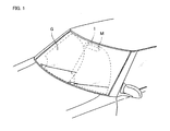
- FIG. 1 is a perspective view showing an example of a car equipped with a liquid drop detector according to the present invention
- Fig. 2 shows a cross-sectional view of the liquid drop detector according to the present invention, of the detector in the figure being attached to a glass plate
- Fig. 3 shows a exploded perspective view of the liquid drop detector according to the present invention.
- a liquid drop detector 1 On an interior portion of a windshield G of an automobile, in particular on a portion being hidden by a rear-view mirror M, is provided a liquid drop detector 1 according to the present invention.
- the position where the liquid drop detector 1 is to be attached should not limited only to the portion of the windshield mentioned in the above, as the detector may also be attached arbitrarily, such as at any peripheral portion on the interior side surface of the windshield G.
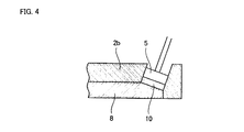
- the liquid drop detector 1 is so constructed that a plurality of elements thereof are provided or stored in a case 2, and the case 2 is constructed with a base 2a of aluminum or resin being bonded onto the interior surface of the windshield G and a cover 2b which is attached to the base 2a by a screw(s).
- the cover 2b can be attached to the base 2a at both ends in the longitudinal direction thereof, however it also can be attached to the base 2a by fixing only one end thereof with the screw while keeping the other end in the longitudinal direction free, fixed by only insertion, so as to allow for a change in the length thereof due to a change of temperature.
- a holder 2c is fixed between the base 2a and the cover 2b, wherein the holder 2c holds a light emitting element 4, such as a LD (Laser Diode) or a LED (Light Emitting Diode), at one end and a light receiving element 5, such as a PD (Photo Diode), at the other end, in the longitudinal direction thereof. Also, between the base 2a and the holder 2c, there is provided a light guiding means 6 for guiding the light emitted from the light emitting element 4 to the light receiving element 5.
- a light emitting element 4 such as a LD (Laser Diode) or a LED (Light Emitting Diode)
- a light receiving element 5 such as a PD (Photo Diode)
- the light guiding means 6 is constructed with a light guiding body 7, comprised of glass into which enters the light emitted from the light emitting element 4, a light guiding body 8 comprised of glass which guides and introduces the emitted light into the above light receiving element 5, a light-guiding body 9 comprised of glass which is disposed with each end thereof overlaying one of the light guiding bodies 7 and 8, and further silicon members 10 inserted between the light guiding bodies 7, 8 and light guiding body 9, and between the light guiding body 9 and the interior surface of the windshield G.
- the silicon members 10 are elastic bodies having a refraction index being approximately equal to that of the light guiding bodies 7, 8 or 9 which are comprised of glass, and to that of the windshield G as well, and the thickness thereof is so set that, under a condition where the cover 2b is attached onto the base 2a, they are fitted tightly between the light guiding bodies 7, 8 and 9 and the windshield G, thereby allowing no air to exist or intrude between the light guiding bodies 7, 8 and 9 and the silicon members 10 nor between the windshield G and the silicon members 10.
- the light does not penetrate through but rather is totally reflected, thereby preventing the light emitted from the light emitting element 4 from reaching the windshield G and preventing the light undergoing total internal reflection within the windshield G from correctly reaching the light receiving element 5.
- the silicon member 10 is also inserted or lies between the light receiving element 5 and the light guiding body 9, so as to prevent any air layer from forming between the light guiding body 9 and the light receiving element 5. Such installation is carried out while applying pressure to avoid any space or air layer therebetween.
- a belt-like silicon material is wound around the light guiding body 9 so as to be set into an opening 20 of the base 2a, however it is possible to dispose a plurality of silicon elements, each individually.
- the light guiding bodies 7 and 8 are formed separately in the example shown in the Figures, they can be formed as one light guiding body. However, in this case, there is a possibility that a portion of the light incident from the light emitting element 4 does not enter into the windshield G but rather enters directly into the light receiving element 5, and therefore the light guiding bodies 7 and 8 are preferably to be formed as divided and separate bodies.
- a space 11 is formed in a center portion. It is preferable to enclose a desiccant therein, since condensation may occur in the space 11 if it is thus formed.
- the light guiding body 7, having a thickness of approximately 3 mm is formed in such a shape that both side surfaces gradually diverge in the direction of light propagation
- the light guiding body 8 having a thickness of approximately 3 mm is formed in such a shape that both side surfaces gradually converge in the direction of light propagation, i.e towards the light receiving element 5.
- the light guiding body 7 By forming the light guiding body 7 into such a shape as mentioned above, it is possible to keep appropriate an opening angle of the light beam incident upon the light guiding body 7 from the light emitting element 4. Also, by forming the light guiding body 8 into such a shape as mentioned above, the amount of light passing through (escaping) can be decreased compared to a case where the light guiding body 8 is formed in a square or rectangular shape (in a plan view thereof), and thereby the utilization ratio of the light emitted from the light emitting element 4 is increased.
- the amount of light escaping at said end surface by total internal reflection can be lowered, thereby increasing the light incident upon the light receiving element 5 so as to improve the sensitivity.
- the surface of the light guiding body 7 opposite to the light emitting element 4 also can be formed or provided with such an oblique surface.
- the light guiding bodies 7 and 8 in such shapes as mentioned above, while they may be produced by cutting and grinding a glass plate, they may also be formed by mold forming without using cutting and grinding processes.
- the light guiding bodies 7, 8 are located inside of an aperture 13 which is formed in the light shielding member 12, being of a sheet-like shape, and at appropriate positions on the surfaces of the light guiding bodies 7, 8, 9 are provided reflection films 14 comprising a metal thin film.
- the reflection films 14 must not be provided on the glass substrate where the light beam is incident upon it at the angle experiencing the total internal reflection.
- a diffraction grating 15 is further provided on an upper surface of the light guiding body 7. This diffraction grating 15 is provided for the purposes of guiding the light from the light emitting element 4 into the light guiding body 7 at a predetermined angle and of reflecting a portion of the light emitted from the light emitting element 4 upon the light receiving element 16 for monitoring.
- the diffraction grating is preferable taking small size and low weight thereof into consideration.
- the diffraction grating means is an optical element, provided on the glass surface on which are formed fine or minute grooves, or the like. It is common that such diffraction gratings are designed with a groove pitch within a range from 0.4 to 3 ⁇ m, and such configurations are applied to a variety of uses. They are primarily used for separating the spectral constituents of light, in particular in a case where monochromatic light is used, and they can be further used for dividing, separating or bending a light beam, by the diffraction effect inherent to light upon passing through a space having a certain size with relation to the wavelength of the light.
- the diffraction grating can be a reflection-type diffraction grating, a slit-type diffraction grating, or a diffraction grating in which the refraction index varies periodically.
- the diffraction grating With use of the diffraction grating, it is possible to introduce the light into the light guiding body 7 at an predetermined angle. Further, by selecting the incident angle upon the diffraction grating as an appropriate angle, it is possible to set up the invention such that the introduced light undergoes total internal reflection within the windshield G. Further, on the basis of the same principle, the diffraction grating may be provided on the light guiding body, so as to introduce the light undergoing total internal reflection within the windshield G onto the light receiving element 5 at an predetermined angle.
- a further method of manufacturing the diffraction grating that may be considered is to use the ablation phenomenon by evaporation of the glass surface in a part thereof, by use of a laser beam.
- the ablation phenomenon is a phenomenon which occurs due to absorption of the laser beam energy by the glass.
- the ablation phenomenon occurs from the top surface layer toward the inside sequentially, thereby obtaining minute machining without causing cracks nor fragmenting of the glass.
- the diffraction grating is formed directly onto the glass from which the light guiding body 7 is formed, however the diffraction grating can be formed on a separate glass in a sheet-like form to be affixed onto the light guiding body 7.
- the light introduced into the windshield G is received by the light receiving element 5 through the silicon member 10 between the light guiding body 9 and the windshield G, the light guiding body 9, the silicon member 10 between the light guiding bodies 9 and 8, and the light guiding body 8.
- the light introduced into the windshield G passes through the surface of windshield G without undergoing total internal reflection therein.
- the light received by the light receiving element 5 is lessened in the amount thereof, thereby enabling detection of the adhesion of rain drops based thereupon so as to output a signal for driving a device or system such as the wiper.
- the liquid drop detector according to the present invention should not be limited only to application in a rain sensor for use in an automobile, but is also applicable to the windshield of an electric train or a window glass of a structure, and the transparent substrate to which the liquid drop detector according to the present invention can be applied may be glass comprised of combined or piled-up layers.
- the liquid drop detector according to the present invention may be attached to an existing glass window, etc., with ease, and the light emitted from the light emitting means can be transmitted to the light receiving means reliably and efficiently. Further, the liquid drop detector according to the present invention prevents light from entering the detector from outside and additionally prevents condensation from forming within the case, thereby further enabling the detection of the adhesion of liquid drops with accuracy and reliability.
- the optical element such as the diffraction grating, etc.
Landscapes
- Engineering & Computer Science (AREA)
- Automation & Control Theory (AREA)
- Mechanical Engineering (AREA)
- Physics & Mathematics (AREA)
- Health & Medical Sciences (AREA)
- Life Sciences & Earth Sciences (AREA)
- Chemical & Material Sciences (AREA)
- Analytical Chemistry (AREA)
- Biochemistry (AREA)
- General Health & Medical Sciences (AREA)
- General Physics & Mathematics (AREA)
- Immunology (AREA)
- Pathology (AREA)
- Investigating Or Analysing Materials By Optical Means (AREA)
- Geophysics And Detection Of Objects (AREA)
Applications Claiming Priority (2)
| Application Number | Priority Date | Filing Date | Title |
|---|---|---|---|
| JP12899098 | 1998-05-12 | ||
| JP10128990A JPH11326185A (ja) | 1998-05-12 | 1998-05-12 | 液滴検出装置 |
Publications (2)
| Publication Number | Publication Date |
|---|---|
| EP0957017A2 true EP0957017A2 (fr) | 1999-11-17 |
| EP0957017A3 EP0957017A3 (fr) | 2000-07-12 |
Family
ID=14998405
Family Applications (1)
| Application Number | Title | Priority Date | Filing Date |
|---|---|---|---|
| EP99303675A Withdrawn EP0957017A3 (fr) | 1998-05-12 | 1999-05-11 | Détecteur de liquide |
Country Status (4)
| Country | Link |
|---|---|
| US (1) | US6147753A (fr) |
| EP (1) | EP0957017A3 (fr) |
| JP (1) | JPH11326185A (fr) |
| KR (1) | KR19990088062A (fr) |
Cited By (6)
| Publication number | Priority date | Publication date | Assignee | Title |
|---|---|---|---|---|
| WO2002102632A1 (fr) * | 2001-06-15 | 2002-12-27 | Robert Bosch Gmbh | Capteur de pluie destine en particulier a un vehicule automobile, et procede de montage d'un capteur de pluie |
| WO2004060729A1 (fr) * | 2002-12-20 | 2004-07-22 | Robert Bosch Gmbh | Detecteur de pluie, destine notamment a un vehicule automobile |
| US6797649B2 (en) | 2000-08-01 | 2004-09-28 | Essilor International Compagnie Generale D'optique | Method for depositing a fluorine-doped silica film |
| EP1598247A3 (fr) * | 2004-03-29 | 2005-12-07 | Robert Bosch Gmbh | Capteur de pluie |
| EP1432600B1 (fr) * | 2001-09-26 | 2008-10-22 | Robert Bosch Gmbh | Capteur holographique, notamment pour la detection d'humidite sur une vitre d'un vehicule automobile |
| CN108387943A (zh) * | 2017-02-03 | 2018-08-10 | 贾培军 | 一种液滴光学检测装置 |
Families Citing this family (11)
| Publication number | Priority date | Publication date | Assignee | Title |
|---|---|---|---|---|
| DE19725287A1 (de) * | 1997-06-14 | 1998-12-17 | Itt Mfg Enterprises Inc | Regensensor mit gebondeten Sensor-Chips |
| JP4374795B2 (ja) * | 2001-04-02 | 2009-12-02 | 株式会社デンソー | 雨滴センサ |
| US6646560B1 (en) | 2001-10-26 | 2003-11-11 | H. P. Intellectual Corp. | Window fan with rain sensing control |
| DE10209615A1 (de) * | 2002-03-05 | 2003-09-18 | Bosch Gmbh Robert | Vorrichtung und Verfahren zur Fixierung eines Sensormittels |
| DE102005018379A1 (de) * | 2005-04-21 | 2006-10-26 | Leopold Kostal Gmbh & Co. Kg | Optoelektronische Sensoreinrichtung |
| JP4518007B2 (ja) * | 2005-11-21 | 2010-08-04 | 株式会社デンソー | 雨滴センサ |
| DE202006017362U1 (de) * | 2006-11-13 | 2008-03-20 | Trw Automotive Electronics & Components Gmbh & Co. Kg | Regensensor |
| JP5845820B2 (ja) * | 2011-11-02 | 2016-01-20 | 株式会社リコー | 撮像ユニット及びそれを備えた車両 |
| EP3279043B1 (fr) * | 2016-08-05 | 2018-12-05 | MEAS France | Système d'assemblage de capteurs |
| JP7041345B2 (ja) * | 2017-12-28 | 2022-03-24 | ミツミ電機株式会社 | 液滴センサ |
| CN114043853B (zh) * | 2021-11-01 | 2023-05-30 | 电子科技大学 | 一种用于固体表面防润湿的气层引入装置及其应用 |
Family Cites Families (13)
| Publication number | Priority date | Publication date | Assignee | Title |
|---|---|---|---|---|
| US3947131A (en) * | 1974-11-04 | 1976-03-30 | Gerhard Karl | Windshield soil detector |
| JPS61116645A (ja) * | 1984-11-09 | 1986-06-04 | Nippon Denso Co Ltd | ウインドシ−ルドワイパ自動制御装置のための液体検出器 |
| JPS62163949A (ja) * | 1986-01-14 | 1987-07-20 | Sharp Corp | 光学式液体検出センサ |
| GB2197068B (en) * | 1986-11-03 | 1990-08-08 | Stc Plc | Optical sensor device |
| US4960996A (en) * | 1989-01-18 | 1990-10-02 | Hochstein Peter A | Rain sensor with reference channel |
| DE4006174C1 (fr) * | 1990-02-28 | 1991-07-25 | Leopold Kostal Gmbh & Co Kg, 5880 Luedenscheid, De | |
| DE4410217C2 (de) * | 1994-03-24 | 2003-12-11 | Bosch Gmbh Robert | Befestigung und Ankopplung eines opto-elektronischen Sensors an einer Scheibe sowie Aufbau des Sensors |
| JPH08261974A (ja) * | 1995-03-23 | 1996-10-11 | Matsushita Electric Works Ltd | 水滴検知ガラス窓 |
| DE19701258A1 (de) * | 1996-01-18 | 1997-07-24 | Itt Mfg Enterprises Inc | Regensensor mit planarer Koppelfolie |
| DE19601802C2 (de) * | 1996-01-19 | 1999-05-06 | Bosch Gmbh Robert | Sensoreinrichtung zum Feststellen eines Benetzungszustandes einer Scheibe |
| JPH1134801A (ja) * | 1997-07-22 | 1999-02-09 | Nippon Sheet Glass Co Ltd | 水滴感応式ワイパ制御装置 |
| JPH1194731A (ja) * | 1997-07-22 | 1999-04-09 | Nippon Sheet Glass Co Ltd | 液体検出機能を備えた透明基板 |
| US5898183A (en) * | 1997-10-16 | 1999-04-27 | Libbey-Owens-Ford Co. | Compact moisture sensor with efficient high obliquity optics |
-
1998
- 1998-05-12 JP JP10128990A patent/JPH11326185A/ja active Pending
-
1999
- 1999-05-06 KR KR1019990016127A patent/KR19990088062A/ko not_active Withdrawn
- 1999-05-10 US US09/307,756 patent/US6147753A/en not_active Expired - Fee Related
- 1999-05-11 EP EP99303675A patent/EP0957017A3/fr not_active Withdrawn
Cited By (7)
| Publication number | Priority date | Publication date | Assignee | Title |
|---|---|---|---|---|
| US6797649B2 (en) | 2000-08-01 | 2004-09-28 | Essilor International Compagnie Generale D'optique | Method for depositing a fluorine-doped silica film |
| WO2002102632A1 (fr) * | 2001-06-15 | 2002-12-27 | Robert Bosch Gmbh | Capteur de pluie destine en particulier a un vehicule automobile, et procede de montage d'un capteur de pluie |
| US6900733B2 (en) | 2001-06-15 | 2005-05-31 | Robert Bosch Gmbh | Rain sensor, particular for a motor vehicle and method for mounting a rain sensor |
| EP1432600B1 (fr) * | 2001-09-26 | 2008-10-22 | Robert Bosch Gmbh | Capteur holographique, notamment pour la detection d'humidite sur une vitre d'un vehicule automobile |
| WO2004060729A1 (fr) * | 2002-12-20 | 2004-07-22 | Robert Bosch Gmbh | Detecteur de pluie, destine notamment a un vehicule automobile |
| EP1598247A3 (fr) * | 2004-03-29 | 2005-12-07 | Robert Bosch Gmbh | Capteur de pluie |
| CN108387943A (zh) * | 2017-02-03 | 2018-08-10 | 贾培军 | 一种液滴光学检测装置 |
Also Published As
| Publication number | Publication date |
|---|---|
| EP0957017A3 (fr) | 2000-07-12 |
| JPH11326185A (ja) | 1999-11-26 |
| KR19990088062A (ko) | 1999-12-27 |
| US6147753A (en) | 2000-11-14 |
Similar Documents
| Publication | Publication Date | Title |
|---|---|---|
| EP0957017A2 (fr) | Détecteur de liquide | |
| KR100682800B1 (ko) | 광 센서 | |
| EP1005634B1 (fr) | Procede de dosage optique avec des angles d'incidence presque perpendiculaires et avec une grande sensibilite aux longueurs d'onde et aux angles d'incidence | |
| US5998782A (en) | Water drop detector on transparent substrate | |
| EP0999104A2 (fr) | Capteur de pluie et système d'exposition pour hologramme | |
| US20110128543A1 (en) | Rain sensor using light scattering | |
| CN1348095A (zh) | 湿气检测器 | |
| EP0866330A2 (fr) | Substrat transparent pour la détection de liquides | |
| EP0893317A2 (fr) | Substrat transparent avec capteur de pluie | |
| EP0919443A2 (fr) | Substrat transparent équipé d'un dispositif de détection d'eau | |
| US5917603A (en) | Wiper control apparatus | |
| EP1308714B1 (fr) | Plaque de mesure pour capteur utilisant la réflexion totale atténuée | |
| EP1553398A1 (fr) | Capteur d'humidite | |
| KR20070084148A (ko) | 차량의 윈드실드 상의 습기를 검출하는 광센서 | |
| US6285037B1 (en) | Liquid drop detection method and apparatus therefor | |
| AU1259800A (en) | Optical sensor | |
| US6239444B1 (en) | Water drop detector on transparent substrate and initiating method and output stabilizing method therefor | |
| US6239570B1 (en) | Wiper controller apparatus of water drop sensitive type | |
| US5278425A (en) | Lens system for moisture sensor device | |
| US7019322B2 (en) | Optical sensor for detecting moisture on a surface | |
| JPS5984141A (ja) | 水滴検知装置 | |
| JP2000131231A (ja) | 液滴検出装置 | |
| JPH1138122A (ja) | 反射測定装置用筐体 | |
| JP3501903B2 (ja) | 水滴検出装置 | |
| JPH1137925A (ja) | 液滴検出装置 |
Legal Events
| Date | Code | Title | Description |
|---|---|---|---|
| PUAI | Public reference made under article 153(3) epc to a published international application that has entered the european phase |
Free format text: ORIGINAL CODE: 0009012 |
|
| AK | Designated contracting states |
Kind code of ref document: A2 Designated state(s): AT BE CH CY DE DK ES FI FR GB GR IE IT LI LU MC NL PT SE |
|
| AX | Request for extension of the european patent |
Free format text: AL;LT;LV;MK;RO;SI |
|
| PUAL | Search report despatched |
Free format text: ORIGINAL CODE: 0009013 |
|
| AK | Designated contracting states |
Kind code of ref document: A3 Designated state(s): AT BE CH CY DE DK ES FI FR GB GR IE IT LI LU MC NL PT SE |
|
| AX | Request for extension of the european patent |
Free format text: AL;LT;LV;MK;RO;SI |
|
| AKX | Designation fees paid | ||
| STAA | Information on the status of an ep patent application or granted ep patent |
Free format text: STATUS: THE APPLICATION IS DEEMED TO BE WITHDRAWN |
|
| 18D | Application deemed to be withdrawn |
Effective date: 20010113 |
|
| REG | Reference to a national code |
Ref country code: DE Ref legal event code: 8566 |