EP0957021A2 - Herstellungsverfahren für den Kranz eines Fahrzeuglenkrads - Google Patents
Herstellungsverfahren für den Kranz eines Fahrzeuglenkrads Download PDFInfo
- Publication number
- EP0957021A2 EP0957021A2 EP99107062A EP99107062A EP0957021A2 EP 0957021 A2 EP0957021 A2 EP 0957021A2 EP 99107062 A EP99107062 A EP 99107062A EP 99107062 A EP99107062 A EP 99107062A EP 0957021 A2 EP0957021 A2 EP 0957021A2
- Authority
- EP
- European Patent Office
- Prior art keywords
- transfer
- mask member
- steering wheel
- rim
- forming
- Prior art date
- Legal status (The legal status is an assumption and is not a legal conclusion. Google has not performed a legal analysis and makes no representation as to the accuracy of the status listed.)
- Granted
Links
- 238000000034 method Methods 0.000 title claims description 38
- 238000004519 manufacturing process Methods 0.000 title claims description 23
- 238000012546 transfer Methods 0.000 claims abstract description 101
- 238000000465 moulding Methods 0.000 claims abstract description 27
- 239000011248 coating agent Substances 0.000 claims abstract description 18
- 238000000576 coating method Methods 0.000 claims abstract description 18
- JOYRKODLDBILNP-UHFFFAOYSA-N Ethyl urethane Chemical compound CCOC(N)=O JOYRKODLDBILNP-UHFFFAOYSA-N 0.000 claims abstract description 14
- 239000000463 material Substances 0.000 claims abstract description 13
- 238000004140 cleaning Methods 0.000 claims abstract description 12
- 230000000873 masking effect Effects 0.000 claims abstract description 10
- 239000004372 Polyvinyl alcohol Substances 0.000 claims description 32
- 229920002451 polyvinyl alcohol Polymers 0.000 claims description 32
- 238000001035 drying Methods 0.000 claims description 9
- 238000000926 separation method Methods 0.000 claims description 6
- 231100000241 scar Toxicity 0.000 claims description 5
- XLYOFNOQVPJJNP-UHFFFAOYSA-N water Substances O XLYOFNOQVPJJNP-UHFFFAOYSA-N 0.000 claims description 5
- 239000000203 mixture Substances 0.000 claims description 4
- LFQSCWFLJHTTHZ-UHFFFAOYSA-N Ethanol Chemical compound CCO LFQSCWFLJHTTHZ-UHFFFAOYSA-N 0.000 claims description 2
- 239000002023 wood Substances 0.000 description 19
- 239000004800 polyvinyl chloride Substances 0.000 description 3
- 229920000915 polyvinyl chloride Polymers 0.000 description 3
- 238000012360 testing method Methods 0.000 description 3
- 239000004743 Polypropylene Substances 0.000 description 2
- XECAHXYUAAWDEL-UHFFFAOYSA-N acrylonitrile butadiene styrene Chemical compound C=CC=C.C=CC#N.C=CC1=CC=CC=C1 XECAHXYUAAWDEL-UHFFFAOYSA-N 0.000 description 2
- 239000004676 acrylonitrile butadiene styrene Substances 0.000 description 2
- 229920000122 acrylonitrile butadiene styrene Polymers 0.000 description 2
- 230000001681 protective effect Effects 0.000 description 2
- 239000011347 resin Substances 0.000 description 2
- 229920005989 resin Polymers 0.000 description 2
- 238000005507 spraying Methods 0.000 description 2
- 229920000049 Carbon (fiber) Polymers 0.000 description 1
- 229920002472 Starch Polymers 0.000 description 1
- 229910000831 Steel Inorganic materials 0.000 description 1
- 229910052782 aluminium Inorganic materials 0.000 description 1
- XAGFODPZIPBFFR-UHFFFAOYSA-N aluminium Chemical compound [Al] XAGFODPZIPBFFR-UHFFFAOYSA-N 0.000 description 1
- 239000004917 carbon fiber Substances 0.000 description 1
- 230000008878 coupling Effects 0.000 description 1
- 238000010168 coupling process Methods 0.000 description 1
- 238000005859 coupling reaction Methods 0.000 description 1
- 230000002950 deficient Effects 0.000 description 1
- 238000007598 dipping method Methods 0.000 description 1
- 238000002845 discoloration Methods 0.000 description 1
- 239000012634 fragment Substances 0.000 description 1
- 239000010985 leather Substances 0.000 description 1
- 229910052751 metal Inorganic materials 0.000 description 1
- 239000002184 metal Substances 0.000 description 1
- VNWKTOKETHGBQD-UHFFFAOYSA-N methane Chemical compound C VNWKTOKETHGBQD-UHFFFAOYSA-N 0.000 description 1
- 238000012986 modification Methods 0.000 description 1
- 230000004048 modification Effects 0.000 description 1
- 229920003023 plastic Polymers 0.000 description 1
- 239000004033 plastic Substances 0.000 description 1
- -1 polypropylene Polymers 0.000 description 1
- 229920001155 polypropylene Polymers 0.000 description 1
- 238000012545 processing Methods 0.000 description 1
- 235000019698 starch Nutrition 0.000 description 1
- 239000008107 starch Substances 0.000 description 1
- 239000010959 steel Substances 0.000 description 1
- 239000004575 stone Substances 0.000 description 1
Images


Classifications
-
- B—PERFORMING OPERATIONS; TRANSPORTING
- B62—LAND VEHICLES FOR TRAVELLING OTHERWISE THAN ON RAILS
- B62D—MOTOR VEHICLES; TRAILERS
- B62D1/00—Steering controls, i.e. means for initiating a change of direction of the vehicle
- B62D1/02—Steering controls, i.e. means for initiating a change of direction of the vehicle vehicle-mounted
- B62D1/04—Hand wheels
- B62D1/06—Rims, e.g. with heating means; Rim covers
-
- B—PERFORMING OPERATIONS; TRANSPORTING
- B44—DECORATIVE ARTS
- B44C—PRODUCING DECORATIVE EFFECTS; MOSAICS; TARSIA WORK; PAPERHANGING
- B44C1/00—Processes, not specifically provided for elsewhere, for producing decorative surface effects
- B44C1/16—Processes, not specifically provided for elsewhere, for producing decorative surface effects for applying transfer pictures or the like
- B44C1/165—Processes, not specifically provided for elsewhere, for producing decorative surface effects for applying transfer pictures or the like for decalcomanias; sheet material therefor
- B44C1/175—Transfer using solvent
Definitions
- the present invention relates to a method for manufacturing a rim of a steering wheel for vehicles, and more particularly, to a method for manufacturing a rim of a steering wheel of high quality using a hydraulic transfer method.
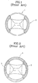
- FIG. 1 shows an example of a method for manufacturing a rim of a steering wheel for vehicles.
- a first molding portion 2 formed of soft PVC or urethane is formed on and around a hub core 1.
- the first molding portion 2 is wrapped by leather 3, and a wood portion 4 is formed around the remaining hub core 1 by processing wood suitable for the shape of the hub core 1 and attaching the processed wood thereto.
- the wood portion 4 can be formed by layering wood laminae, cut in the form of a sheet, or mixing sawdust with resin and molding the mixture and attaching a thin wood sheet thereon.
- a method for manufacturing a rim of a steering wheel for vehicles which comprises the steps of: (A) forming a molding member of a urethane material which constitutes a part of the rim of a steering wheel; (B) forming a masking portion by attaching a first mask member to a part of a surface of the molding member; (C) forming a first transfer surface by performing a hydraulic transfer on a surface where the first mask member does not adhere; (D) forming a coating film on the first transfer surface; (E) removing the first mask member to reveal a surface where transfer is not performed; (F) performing a second hydraulic transfer on the surface where transfer is not performed; and (G) cleaning the coating film.
- a method for manufacturing a rim of a steering wheel for vehicles which comprises the steps of: (A) forming a molding member of a urethane material which constitutes a part of the rim of a steering wheel; (B) forming a masking portion by attaching a first mask member to a part of a surface of the molding member; (C) forming a first transfer surface by performing a hydraulic transfer on a surface where the first mask member does not adhere; (D) attaching a second mask member to the first transfer surface and removing the first mask member; and (E) performing a second hydraulic transfer on the surface where the second mask member does not adhere.
- a method for manufacturing a rim of a steering wheel for vehicles which comprises the steps of (A) forming a molding member of a urethane material which constitutes a part of the rim of a steering wheel; (B) forming a masking portion by attaching a first mask member to a part of a surface of the molding member; (C) marking a junction line by marking a blade scar approximately at a middle portion of the mask member of the rim of a steering wheel which is placed on a horizontal rotatable table and removing a part of the mask member disposed under the junction line; (D) covering an upper portion of the mask member which is not removed; (E) performing a transfer on a lower surface under the junction line and cleaning and drying the transferred surface and coating a PVA solution on the transferred surface and drying the coated surface; (F) marking a separation line by placing the rim of a steering wheel on the horizontal rotatable table and adjusting and fixing the height of a blade to be disposed about
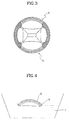
- a second molding portion 5 is formed on and around the hub core 1 of FIG. 1 in a hydraulic transfer method.
- the second molding portion 2 is formed of soft or hard urethane by molding urethane, preferably hard urethane, and performing the hydraulic transfer method according to the present invention which will be described later.
- the second molding portion 5 can be formed of a material made by adding sawdust into resin, In addition to the above materials. Any material such as ABS (acrylonitrile butadiene styrene), PP (polypropylene) or PVC (polyvinyl chloride) can be used therefor.
- the material of the molding portion of a steering wheel must meet various test requirements, particularly, the material should not generate sharp fragments to harm humans in a crash test.
- urethane which is used for the present invention meets all requirements and is considered to be preferable.
- FIG. 4 shows a method of transferring a predetermined pattern on a portion of the second molding portion 5 according to the present invention.
- the second molding portion 5 only is separated from the steering wheel.
- a bent circular bar which is the result of the above separation, is masked with a first mask member 8 lengthwise and half the circumference of the section of the bar.
- a tape or rubber is used for the first masking member 8.
- a transfer film 6 is placed to float on water 7 and a portion that is not masked is located to the bottom and pushed downward above the transfer film 6. Then, a first transfer is performed due to hydraulic pressure. Consequently, the surface where the transfer is performed has a pattern, e.g., a wood pattern.
- the surface where the first transfer is performed is coated with PVA (polyvinyl alcohol) solution and dried.
- PVA polyvinyl alcohol
- the PVA solution above is water-soluble.
- a film is formed to protect a printed pattern layer formed thereunder and prevent overlapping of pattens.
- the coating film in the present invention is not limited to PVA, other materials which are water-soluble and can form a film when dried to protect a printed pattern layer already formed thereunder without discoloration or damage can be used therefor.
- starch farina
- the second transfer is performed on the remaining surface in the same manner as the first transfer.
- the transfer may be made on a part of the area where a pattern is already formed and the coating film 9 is formed thereon.
- the area where a pattern is already formed and the coating film 9 is formed thereon is cleaned with hot water, preferably, over about 30°C, the area is melted and washed out so that the pattern formed on the coating film 9 through the second transfer is removed and the pattern formed through the first transfer is clearly revealed.
- a clearly printed pattern can be formed without damage to the shape of the pattern such as overlapping, extending, or distorting of patterns. Also, even though the edge of the first mask member 8 is not accurately attached in a form of covering about half the surface to be subject to the transfer, patterns can be accurately matched when the second transfer is performed.
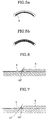
- the edge of an end portion of the first mask member 8 closely contacting an object subject to the transfer is formed to be slanted at an angle of 60° or less with respect to the horizontal surface as shown in FIG. 6. Then, the patterns separately transferred through the first and second transfers are smoothly connected at the boundary area between the patterns.
- the edge of the first mask member 8 is formed over 60°, for example, nearly 90° as shown in FIG. 7, bubbles 10 are trapped between the transfer film 6 and the first mask member 8 and cannot escape therefrom, thus, when a transfer is performed, a print is not made on the connection area between the first and second transfers. As a result, the portion where no transfer is made becomes a form of a strip.
- a pattern is accurately and separately transferred on the hard urethane molding portion of a steering wheel that is an object to be subject to the transfer using the first mask member 8 and the coating film 9 through the first and second transfer steps.
- two or more patterns can be separately transferred on the same surface through first, second and third transfer steps so that various patterns can be obtained.
- FIGS. 8a through 8d show another preferred embodiment of the present invention.
- a first transfer surface 1 is first formed on the bottom surface. After the first transfer surface 1 is cleaned and dried, the first mask member 8 is removed, as shown in FIG. 4, and the first transfer surface 11 is revealed as shown in FIG. 8a. A second mask member 12 where the transfer is performed is wrapped on the first transfer surface 11 as shown in FIG. 8b.
- a second transfer surface 13 is formed as shown in FIG. 8c.
- the second transfer surface 13 is cleaned and dried, or dried without cleaning, and the second mask member 12 shown in FIG. 8c is removed. Then, a clear printed pattern can be formed as shown in FIG. 8d.
- the second mask member 12 is coupled with the distance (c) such that the surface where the pattern is already formed can be revealed as long as a predetermined length.
- the distance is preferably 0.1-0.4 mm. Although the distance can be slightly different according to the members, in a particular case of manufacturing a steering wheel for vehicles, a set of 0.2 mm results in an accurate match of patterns according to actual experiences.
- a non-transfer strip 14 is generated as shown in FIG. 11. If the distance (c) is too wide, patterns are overlapped on the transfer surface.
- the pattern of the transfer film used in the hydraulic transfer method according to the present invention is described to be a typical wood pattern for showing the texture of wood, the present invention is not limited thereto. Any form of pattern, for example, a stone pattern, a latticed carbon fiber pattern or a metal surface pattern can be used therefor.
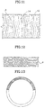
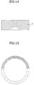
- a transfer film having a linear wood pattern as shown in FIG. 12 results in an unnatural shape as shown in FIG. 13, not giving a texture of wood and being inferior in view of aesthetics. It is preferable to use the transfer film 6 having a pattern as shown in FIG. 14. As shown in FIG. 15, a pattern is formed along a rim of a steering wheel. The pattern as shown in FIG. 14 can be prepared and designed using computer graphics to be suitable for the shape of the rim.
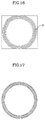
- FIG. 16 Another preferred embodiment of the pattern of the transfer film 6 is shown in FIG. 16.
- the entire circular pattern above designed using computer graphics can be transferred on a rim of a steering wheel with one transfer.
- FIG. 17 shows the steering wheel where the wood pattern is smoothly connected in a circular form.
- FIGS. 18 through 23 show yet another preferred embodiment of the present invention in which a mask member is used.
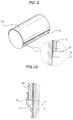
- a mask member 18 of a strip shape having a width of about 4-5 mm is attached to the inner and outer circumferential parts of a rim of a steering wheel 22.
- the rim of the steering wheel 22 is placed on an upper plate 21 of a horizontally rotatable table 20 and fixed by a clamp 23, as shown in FIG. 19.
- a blade holder 24 capable of adjusting the height of a blade 25 is installed on the upper plate 21.
- the blade 25 is fixedly held by the blade holder 24 such that the height of the blade 25 can be flushed with a junction line 8a which is a dotted line marked approximately in the middle of the mask member 18.
- a junction line 8a which is a dotted line marked approximately in the middle of the mask member 18.
- the above step of incising the mask member 18 adhering to the rim of the steering wheel 22 is performed from the inner and outer circumferential side of the rim of the steering wheel 22 using the blade holder 24.
- the mask member 18 can be incised by rotating the upper plate 21 where the steering wheel 22 is fixed and fixedly holding the blade holder 24 with a hand.
- the mask member 18 can be incised by rotating the blade holder 24 from the inner and outer circumferential side of the rim of the steering wheel 22 while keeping the upper plate 21 where the rim of the steering wheel 22 is fixed not to rotate.
- a PVA solution is coated on a surface b and dried and transfer is performed on a surface a .
- the PVA solution is made by mixing PVA and water in a weight ratio of 1(PVA):12-16(water) and completely solving the mixture at the temperature of 60-70°C and adding alcohol to be at 15-20wt%.
- the above PVA solution dries fast and forms the thinnest film so that the working speed is faster and spraying the PVA solution is possible and a cleaning step is made easy.
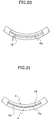
- the height of the blade 25 disposed at the right side in the drawing is adjusted to be about 0.05-0.2 mm lower than the height of the left blade 25 used previously to draw a (dotted) separation line 8b as shown in FIG. 21.
- the remaining mask member 18 and a part of the PVA film shown in FIG. 21 are removed and a second transfer is performed on the surface b . After cleaning and drying the surface b , a clear transfer is completed so that no non-transferred surface is generated and there is no overlapping of the transferred patterns.
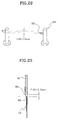
- FIG. 23 shows a magnified section of a major portion around the mask member 18 shown in FIG. 21 before the transfer on the surface b is performed.
- a PVA coating film 19 is formed overlapping the mask member 18.
- the mask member 18 is removed by forming a separation line 8b which is a second blade scar about 0.05-0.2 mm under the blade scar of the middle junction line 8a, the PVA protective film 19 and the mask member 19 formed from and above the separation line 8b are removed.
- the same result can be obtained by attaching a mask member, instead of coating a PVA solution on the surface b .
- the surface b should not be stained with the PVA solution.
- the mask member can be saved and a step relating to attachment of the mask member can be omitted.
- the PVA solution when the PVA solution is coated on the surface a , since the surface b is covered with the mask member, the PVA solution can be coated by a spraying or dipping method so that the working time can be reduced.
- the preferred embodiments described with reference to FIGS. 18 through 23 enable a considerably fast working speed so that mass production is possible and uniformity of products is improved, lowering the defective rate.
- a rim of a steering wheel of high quality can be manufactured in mass.
- the present invention for forming a wood pattern, for example, on a hard urethane gives not only the same touch and feel as that of natural wood, but also superior texture.
- a transfer of a pattern or picture on a product having a complicated bent portion which is difficult to transfer a pattern can be clearly performed without an unsmooth connection portion or a step line between patterns or pictures.
- the present invention covers a method for manufacturing a rim of a steering wheel for vehicles, the present invention is not limited thereto. It is obvious that a transfer can be performed on surfaces of any kind of product such as plastics, aluminum, steel, or wood, having a complicated bent or curved portion.
Landscapes
- Engineering & Computer Science (AREA)
- Chemical & Material Sciences (AREA)
- Combustion & Propulsion (AREA)
- Transportation (AREA)
- Mechanical Engineering (AREA)
- Steering Controls (AREA)
- Printing Methods (AREA)
- Application Of Or Painting With Fluid Materials (AREA)
- Decoration By Transfer Pictures (AREA)
Applications Claiming Priority (10)
| Application Number | Priority Date | Filing Date | Title |
|---|---|---|---|
| KR1019980017425A KR100319260B1 (ko) | 1998-05-14 | 1998-05-14 | 수압전사방법을이용한자동차용고급스티어링휠림의제조방법 |
| KR9817425 | 1998-05-14 | ||
| KR9817424 | 1998-05-14 | ||
| KR1019980017424A KR100275548B1 (ko) | 1998-05-14 | 1998-05-14 | 수압전사방법 |
| KR9836990 | 1998-09-08 | ||
| KR9836991 | 1998-09-08 | ||
| KR1019980036990A KR100309440B1 (ko) | 1998-09-08 | 1998-09-08 | 수압전사방법및이를이용한자동차용스티어링휠림의제조방법 |
| KR1019980036991A KR100309441B1 (ko) | 1998-09-08 | 1998-09-08 | 자동차용고급스티어링휠림의제조방법 |
| KR1019990003368A KR100306210B1 (ko) | 1999-02-02 | 1999-02-02 | 자동차용 스티어링휠 림의 제조방법 |
| KR9903368 | 1999-02-02 |
Publications (3)
| Publication Number | Publication Date |
|---|---|
| EP0957021A2 true EP0957021A2 (de) | 1999-11-17 |
| EP0957021A3 EP0957021A3 (de) | 2002-11-06 |
| EP0957021B1 EP0957021B1 (de) | 2005-07-13 |
Family
ID=36217607
Family Applications (1)
| Application Number | Title | Priority Date | Filing Date |
|---|---|---|---|
| EP99107062A Expired - Lifetime EP0957021B1 (de) | 1998-05-14 | 1999-04-09 | Herstellungsverfahren für den Kranz eines Fahrzeuglenkrads |
Country Status (9)
| Country | Link |
|---|---|
| US (1) | US6214154B1 (de) |
| EP (1) | EP0957021B1 (de) |
| JP (1) | JP3117684B2 (de) |
| CN (1) | CN1106965C (de) |
| BR (1) | BR9901257A (de) |
| CA (1) | CA2269002C (de) |
| DE (1) | DE69926097T2 (de) |
| PL (1) | PL332524A1 (de) |
| TW (1) | TW415898B (de) |
Cited By (4)
| Publication number | Priority date | Publication date | Assignee | Title |
|---|---|---|---|---|
| EP1179434A1 (de) * | 2000-08-11 | 2002-02-13 | Youn-soo, Cho | Transferdruckmethode unter Flüssigkeitsdruck für den Lenkradkranz eines Automobils |
| US6719866B2 (en) * | 2000-01-10 | 2004-04-13 | Cho Youn-Soo | Liquid pressure transfer printing method of steering wheel rim for automobile |
| US6723197B2 (en) * | 2000-03-25 | 2004-04-20 | Cho Youn-Soo | Liquid pressure transfer printing method for steering wheel rim of automobile |
| WO2005009748A1 (en) * | 2003-07-25 | 2005-02-03 | Antonio Di Riso | Mdc 2 carbon effect |
Families Citing this family (9)
| Publication number | Priority date | Publication date | Assignee | Title |
|---|---|---|---|---|
| JP3388404B2 (ja) * | 1999-06-18 | 2003-03-24 | 株式会社キュービック | ループ状のワーク部材に対する液圧転写方法並びにこの方法を適用した加飾製品 |
| JP2001096993A (ja) * | 1999-09-30 | 2001-04-10 | Cubic:Kk | ステアリングホイール等のワークに対する液圧転写方法並びにこれに適用される転写フィルム並びにこの方法を適用した加飾製品 |
| KR100470680B1 (ko) * | 2002-05-29 | 2005-03-08 | 주식회사 화진테크 | 스티어링 휠의 표면 자동전사방법 및 장치 |
| US20040262805A1 (en) * | 2003-06-30 | 2004-12-30 | Bostick William E. | Leather stylized steering wheel |
| KR100944568B1 (ko) | 2005-04-26 | 2010-02-25 | 나가시마고우게이 가부시키가이샤 | 유사상감 가식체의 제조방법 및 그 제조방법으로 제조된 유사상감 가식체 |
| US20090045541A1 (en) * | 2007-08-13 | 2009-02-19 | Trw Vehicle Safety Systems Inc. | Vehicle steering wheel, vehicle interior trim component or other article with a wood appearance portion |
| US20100244539A1 (en) * | 2009-03-30 | 2010-09-30 | Chris Kardassilaris | Vehicle seating material with hydrographic design |
| KR101712340B1 (ko) * | 2009-10-30 | 2017-03-06 | 가부시키가이샤 한도오따이 에네루기 켄큐쇼 | 구동 회로, 구동 회로를 포함하는 표시 장치, 및 표시 장치를 포함하는 전자 기기 |
| JP6473053B2 (ja) * | 2014-07-07 | 2019-02-20 | 三ツ星ベルト株式会社 | ベルト及びベルトの製造方法 |
Family Cites Families (19)
| Publication number | Priority date | Publication date | Assignee | Title |
|---|---|---|---|---|
| US3726152A (en) * | 1970-05-18 | 1973-04-10 | Izumi Motor Car Co Ltd Kk | Steering wheel for motor car |
| US3802291A (en) * | 1972-10-31 | 1974-04-09 | Sheller Globe Corp | Soft steering wheel rim |
| US4010057A (en) * | 1974-08-12 | 1977-03-01 | Kabushiki Kaisha Kobayashi | Printing apparatus |
| US4229239A (en) * | 1977-07-27 | 1980-10-21 | Dai Nippon Insatsu Kabushiki Kaisha | Transfer printing method |
| US4231829A (en) * | 1978-05-16 | 1980-11-04 | Nippon Gohsei Kagaku Kogyo Kabushiki Kaisha | Process of transfer printing |
| US4350550A (en) * | 1980-05-16 | 1982-09-21 | Voplex Corporation | Method of decorating contrasting regions of a molded resin panel |
| JPS60143961A (ja) | 1983-12-30 | 1985-07-30 | Kiyuubitsuku Eng:Kk | 印刷方法 |
| JPS615981A (ja) * | 1984-06-20 | 1986-01-11 | Molten Corp | ステアリングホイ−ルの木目模様印刷方法 |
| CN1010760B (zh) * | 1984-11-13 | 1990-12-12 | 三菱电机株式会社 | 装饰板的制造方法 |
| JPS61130081A (ja) | 1984-11-29 | 1986-06-17 | Kiyuubitsuku Eng:Kk | 印刷方法 |
| IT1237600B (it) * | 1989-10-05 | 1993-06-08 | Gallino Componenti Plastici | Procedimento per la fabbricazione mediante stampaggio di materia plastica di un volante di autoveicolo avente l'aspetto di un volante di legno e volante ottenuto tramite il suddetto procedimento. |
| US5183688A (en) * | 1989-10-30 | 1993-02-02 | Sorko Ram Paul | Convex reflective sign and method of making same |
| US5750190B1 (en) * | 1990-11-16 | 2000-01-25 | Cal West Equipment Co Inc | Protective coating and method of using such coating |
| JP3401579B2 (ja) | 1993-10-21 | 2003-04-28 | 株式会社キュービック | 液圧転写方法 |
| JP3399700B2 (ja) | 1995-06-15 | 2003-04-21 | 藤倉化成株式会社 | 水圧転写方法 |
| CN1056120C (zh) * | 1996-08-29 | 2000-09-06 | 林权树 | 汽车方向盘的制造方法 |
| US5786028A (en) * | 1996-09-05 | 1998-07-28 | Cantwell; Jay S. | Masking tape and method |
| JP3890454B2 (ja) * | 1997-06-03 | 2007-03-07 | 株式会社キュービック | 液圧転写印刷が施されたステアリングホイールの製造方法 |
| JPH1159093A (ja) * | 1997-08-22 | 1999-03-02 | Nippon Plast Co Ltd | 転写印刷方法 |
-
1999
- 1999-04-02 JP JP11095930A patent/JP3117684B2/ja not_active Expired - Fee Related
- 1999-04-02 TW TW088105285A patent/TW415898B/zh not_active IP Right Cessation
- 1999-04-08 US US09/288,015 patent/US6214154B1/en not_active Expired - Fee Related
- 1999-04-09 EP EP99107062A patent/EP0957021B1/de not_active Expired - Lifetime
- 1999-04-09 DE DE69926097T patent/DE69926097T2/de not_active Expired - Fee Related
- 1999-04-14 PL PL99332524A patent/PL332524A1/xx not_active Application Discontinuation
- 1999-04-14 CA CA002269002A patent/CA2269002C/en not_active Expired - Fee Related
- 1999-04-15 BR BR9901257-0A patent/BR9901257A/pt not_active IP Right Cessation
- 1999-04-15 CN CN99105600A patent/CN1106965C/zh not_active Expired - Fee Related
Non-Patent Citations (1)
| Title |
|---|
| None |
Cited By (6)
| Publication number | Priority date | Publication date | Assignee | Title |
|---|---|---|---|---|
| US6719866B2 (en) * | 2000-01-10 | 2004-04-13 | Cho Youn-Soo | Liquid pressure transfer printing method of steering wheel rim for automobile |
| US6723197B2 (en) * | 2000-03-25 | 2004-04-20 | Cho Youn-Soo | Liquid pressure transfer printing method for steering wheel rim of automobile |
| EP1272383A4 (de) * | 2000-03-25 | 2005-03-09 | Youn-Soo Cho | Transferdruckmethode unter flüssigkeitsdruck für den lenkradkranz eines automobils |
| EP1179434A1 (de) * | 2000-08-11 | 2002-02-13 | Youn-soo, Cho | Transferdruckmethode unter Flüssigkeitsdruck für den Lenkradkranz eines Automobils |
| US6541074B2 (en) * | 2000-08-11 | 2003-04-01 | Cho Youn-Soo | Liquid pressure transfer printing method for steering wheel rim of automobile |
| WO2005009748A1 (en) * | 2003-07-25 | 2005-02-03 | Antonio Di Riso | Mdc 2 carbon effect |
Also Published As
| Publication number | Publication date |
|---|---|
| TW415898B (en) | 2000-12-21 |
| CN1106965C (zh) | 2003-04-30 |
| CA2269002C (en) | 2004-01-13 |
| US6214154B1 (en) | 2001-04-10 |
| JPH11321663A (ja) | 1999-11-24 |
| BR9901257A (pt) | 2000-01-04 |
| DE69926097T2 (de) | 2006-05-11 |
| EP0957021A3 (de) | 2002-11-06 |
| CA2269002A1 (en) | 1999-11-14 |
| EP0957021B1 (de) | 2005-07-13 |
| PL332524A1 (en) | 1999-11-22 |
| JP3117684B2 (ja) | 2000-12-18 |
| CN1235916A (zh) | 1999-11-24 |
| DE69926097D1 (de) | 2005-08-18 |
Similar Documents
| Publication | Publication Date | Title |
|---|---|---|
| EP0957021B1 (de) | Herstellungsverfahren für den Kranz eines Fahrzeuglenkrads | |
| JP2662005B2 (ja) | 同時成形及び転写 | |
| US4061516A (en) | Patching technique for damaged, printed design | |
| JPS591684A (ja) | 微小ラインダイス型とその製造方法 | |
| EP2151318A1 (de) | Verfahren zur herstellung eines gegenüber elektrischen wellen transparenten transfermaterials | |
| US20040197536A1 (en) | Heat applied graphics and method | |
| JP2006142836A (ja) | 模造面取りガラスアップリケ | |
| JPH0570179A (ja) | 装飾的被覆をガラスに形成する方法及び装置 | |
| EP1179434B1 (de) | Transferdruckmethode unter Flüssigkeitsdruck für den Lenkradkranz eines Automobils | |
| JP2001524402A (ja) | 表面模様の迅速原型化方法 | |
| US5755911A (en) | Method for making a custom shim for a die component having blind holes | |
| CN102958675A (zh) | 车辆用保护膜的取模型方法以及车辆用保护膜的制造方法 | |
| US4702942A (en) | Deco-plex process | |
| US20060174748A1 (en) | Guitar fret board overlays and method for making overlays | |
| JPH07308976A (ja) | 装飾製品の製造方法及びこの方法により得られた製品 | |
| KR940011822B1 (ko) | 보호용 투명피복층을 가지는 건식전사제품 | |
| JP2578554B2 (ja) | 玉杢模様の突板を貼付けた自動車用ハンドルの製造方法 | |
| US20030041959A1 (en) | Pattern for glass cutting and method for using the pattern | |
| JP2001162619A (ja) | インサート成形用シートとこれを用いたインサート成形品 | |
| KR100424352B1 (ko) | 인서트 몰딩용 필름 제조방법 | |
| KR100319260B1 (ko) | 수압전사방법을이용한자동차용고급스티어링휠림의제조방법 | |
| WO1999028535A1 (en) | Etching methods | |
| JP2002172896A (ja) | 液圧転写方法 | |
| JPH06135196A (ja) | ステッカー及びディカル形成方法 | |
| JPS5887047A (ja) | 化粧合板の製法 |
Legal Events
| Date | Code | Title | Description |
|---|---|---|---|
| PUAI | Public reference made under article 153(3) epc to a published international application that has entered the european phase |
Free format text: ORIGINAL CODE: 0009012 |
|
| AK | Designated contracting states |
Kind code of ref document: A2 Designated state(s): AT BE CH CY DE DK ES FI FR GB GR IE IT LI LU MC NL PT SE |
|
| AX | Request for extension of the european patent |
Free format text: AL;LT;LV;MK;RO;SI |
|
| PUAL | Search report despatched |
Free format text: ORIGINAL CODE: 0009013 |
|
| AK | Designated contracting states |
Kind code of ref document: A3 Designated state(s): AT BE CH CY DE DK ES FI FR GB GR IE IT LI LU MC NL PT SE |
|
| AX | Request for extension of the european patent |
Free format text: AL;LT;LV;MK;RO;SI |
|
| RIC1 | Information provided on ipc code assigned before grant |
Free format text: 7B 62D 1/06 A, 7B 44C 1/175 B, 7B 62D 1/04 B |
|
| 17P | Request for examination filed |
Effective date: 20021007 |
|
| 17Q | First examination report despatched |
Effective date: 20030213 |
|
| AKX | Designation fees paid |
Designated state(s): DE FR GB IT |
|
| GRAP | Despatch of communication of intention to grant a patent |
Free format text: ORIGINAL CODE: EPIDOSNIGR1 |
|
| GRAS | Grant fee paid |
Free format text: ORIGINAL CODE: EPIDOSNIGR3 |
|
| GRAA | (expected) grant |
Free format text: ORIGINAL CODE: 0009210 |
|
| AK | Designated contracting states |
Kind code of ref document: B1 Designated state(s): DE FR GB IT |
|
| PG25 | Lapsed in a contracting state [announced via postgrant information from national office to epo] |
Ref country code: IT Free format text: LAPSE BECAUSE OF FAILURE TO SUBMIT A TRANSLATION OF THE DESCRIPTION OR TO PAY THE FEE WITHIN THE PRE;WARNING: LAPSES OF ITALIAN PATENTS WITH EFFECTIVE DATE BEFORE 2007 MAY HAVE OCCURRED AT ANY TIME BEFORE 2007. THE CORRECT EFFECTIVE DATE MAY BE DIFFERENT FROM THE ONE RECORDED.SCRIBED TIME-LIMIT Effective date: 20050713 |
|
| REG | Reference to a national code |
Ref country code: GB Ref legal event code: FG4D |
|
| REF | Corresponds to: |
Ref document number: 69926097 Country of ref document: DE Date of ref document: 20050818 Kind code of ref document: P |
|
| PG25 | Lapsed in a contracting state [announced via postgrant information from national office to epo] |
Ref country code: GB Free format text: LAPSE BECAUSE OF NON-PAYMENT OF DUE FEES Effective date: 20060409 |
|
| ET | Fr: translation filed | ||
| PLBE | No opposition filed within time limit |
Free format text: ORIGINAL CODE: 0009261 |
|
| STAA | Information on the status of an ep patent application or granted ep patent |
Free format text: STATUS: NO OPPOSITION FILED WITHIN TIME LIMIT |
|
| 26N | No opposition filed |
Effective date: 20060418 |
|
| GBPC | Gb: european patent ceased through non-payment of renewal fee |
Effective date: 20060409 |
|
| PGFP | Annual fee paid to national office [announced via postgrant information from national office to epo] |
Ref country code: DE Payment date: 20070419 Year of fee payment: 9 |
|
| PGFP | Annual fee paid to national office [announced via postgrant information from national office to epo] |
Ref country code: FR Payment date: 20070427 Year of fee payment: 9 |
|
| PG25 | Lapsed in a contracting state [announced via postgrant information from national office to epo] |
Ref country code: DE Free format text: LAPSE BECAUSE OF NON-PAYMENT OF DUE FEES Effective date: 20081101 |
|
| REG | Reference to a national code |
Ref country code: FR Ref legal event code: ST Effective date: 20081231 |
|
| PG25 | Lapsed in a contracting state [announced via postgrant information from national office to epo] |
Ref country code: FR Free format text: LAPSE BECAUSE OF NON-PAYMENT OF DUE FEES Effective date: 20080430 |