EP0957224A1 - Dispositif de blocage en basculement - Google Patents
Dispositif de blocage en basculement Download PDFInfo
- Publication number
- EP0957224A1 EP0957224A1 EP99103823A EP99103823A EP0957224A1 EP 0957224 A1 EP0957224 A1 EP 0957224A1 EP 99103823 A EP99103823 A EP 99103823A EP 99103823 A EP99103823 A EP 99103823A EP 0957224 A1 EP0957224 A1 EP 0957224A1
- Authority
- EP
- European Patent Office
- Prior art keywords
- tilt
- spring element
- lock device
- doors according
- faceplate
- Prior art date
- Legal status (The legal status is an assumption and is not a legal conclusion. Google has not performed a legal analysis and makes no representation as to the accuracy of the status listed.)
- Granted
Links
- 239000002861 polymer material Substances 0.000 claims description 4
- 239000004760 aramid Substances 0.000 claims description 3
- 229920003235 aromatic polyamide Polymers 0.000 claims description 3
- 238000005452 bending Methods 0.000 description 18
- 210000002414 leg Anatomy 0.000 description 10
- 239000000463 material Substances 0.000 description 6
- 239000000725 suspension Substances 0.000 description 4
- 238000004519 manufacturing process Methods 0.000 description 3
- 208000012886 Vertigo Diseases 0.000 description 2
- 238000005516 engineering process Methods 0.000 description 2
- 238000000034 method Methods 0.000 description 2
- 230000002265 prevention Effects 0.000 description 2
- 238000005299 abrasion Methods 0.000 description 1
- 230000015572 biosynthetic process Effects 0.000 description 1
- LYKJEJVAXSGWAJ-UHFFFAOYSA-N compactone Natural products CC1(C)CCCC2(C)C1CC(=O)C3(O)CC(C)(CCC23)C=C LYKJEJVAXSGWAJ-UHFFFAOYSA-N 0.000 description 1
- 238000006073 displacement reaction Methods 0.000 description 1
- 230000005489 elastic deformation Effects 0.000 description 1
- 239000013013 elastic material Substances 0.000 description 1
- 210000003414 extremity Anatomy 0.000 description 1
- 230000005484 gravity Effects 0.000 description 1
- 230000007774 longterm Effects 0.000 description 1
- 239000002184 metal Substances 0.000 description 1
- 239000004033 plastic Substances 0.000 description 1
- 210000000689 upper leg Anatomy 0.000 description 1
Images




Classifications
-
- E—FIXED CONSTRUCTIONS
- E05—LOCKS; KEYS; WINDOW OR DOOR FITTINGS; SAFES
- E05D—HINGES OR SUSPENSION DEVICES FOR DOORS, WINDOWS OR WINGS
- E05D15/00—Suspension arrangements for wings
- E05D15/48—Suspension arrangements for wings allowing alternative movements
- E05D15/52—Suspension arrangements for wings allowing alternative movements for opening about a vertical as well as a horizontal axis
- E05D15/5217—Tilt-lock devices
-
- E—FIXED CONSTRUCTIONS
- E05—LOCKS; KEYS; WINDOW OR DOOR FITTINGS; SAFES
- E05D—HINGES OR SUSPENSION DEVICES FOR DOORS, WINDOWS OR WINGS
- E05D15/00—Suspension arrangements for wings
- E05D15/48—Suspension arrangements for wings allowing alternative movements
- E05D15/52—Suspension arrangements for wings allowing alternative movements for opening about a vertical as well as a horizontal axis
- E05D15/522—Suspension arrangements for wings allowing alternative movements for opening about a vertical as well as a horizontal axis with disconnecting means for the appropriate pivoting parts
- E05D15/523—Suspension arrangements for wings allowing alternative movements for opening about a vertical as well as a horizontal axis with disconnecting means for the appropriate pivoting parts using movable rods
-
- E—FIXED CONSTRUCTIONS
- E05—LOCKS; KEYS; WINDOW OR DOOR FITTINGS; SAFES
- E05Y—INDEXING SCHEME ASSOCIATED WITH SUBCLASSES E05D AND E05F, RELATING TO CONSTRUCTION ELEMENTS, ELECTRIC CONTROL, POWER SUPPLY, POWER SIGNAL OR TRANSMISSION, USER INTERFACES, MOUNTING OR COUPLING, DETAILS, ACCESSORIES, AUXILIARY OPERATIONS NOT OTHERWISE PROVIDED FOR, APPLICATION THEREOF
- E05Y2900/00—Application of doors, windows, wings or fittings thereof
- E05Y2900/10—Application of doors, windows, wings or fittings thereof for buildings or parts thereof
- E05Y2900/13—Type of wing
- E05Y2900/148—Windows
Definitions
- the invention relates to a tilt lock device for Tilt and turn windows and doors according to the generic term of Claim 1, and a spring element and a Forend rail for use with a tilt lock device.
- Such a tilt lock device is from DE 36 27 043 known.
- the task of such a toggle latch device generally consists of ensuring the locking function of the window or the door and on the other hand the setting "lock” the desired switching function, to enable "rotate” and "tilt". Beyond that especially in the tilted position of the window or door leaf an effective prevention of incorrect switching purposes Accident prevention on the one hand and an anti-lift device for To accomplish the purpose of burglary protection on the other hand.
- the known rocker bar device a bending rod spring Application in a longitudinal slot in a faceplate in With respect to the faceplate is stationary.
- the bending bar spring has a U-shape in plan view, the Bending rod spring itself a rectangular cross section has and in the longitudinal slot of the faceplate such is recorded that the rectangular cross section transverse to Level of the faceplate is upright.
- the bending bar spring protrudes the faceplate by at most 1 mm, at least 2 mm of the height of the bending rod spring in the longitudinal slot of the Face plate is added.
- the longitudinal slot has in the upper straight to parallel to each other up to medium length range running surfaces on which the outer surfaces of the Apply the bending rod spring.
- the bending rod spring fits in a form-fitting manner by means of her two legs protruding over the faceplate each molded into the back of a swivel tab parallel grooves.
- the drive rod is in the lower Switched position transferred, so the two legs of the Bending rod spring only in the one adjacent to the bearing journal Length range of the swivel bracket with its longitudinal grooves in a form-fitting manner Intervention. Is by tilting the wing now the swivel tab from its parallel position The faceplate swivels, so there is an elastic Deformation on the two legs of the bending rod spring, the ends of the two limbs of the flexible rod spring, which follow the swivel movement of the swivel bracket and in immerse the extensions.
- the bending rod spring in the longitudinal grooves of the swivel bracket heavy wear in the area of the bearing journal to lead.
- the bending rod spring can also be in the area of Wedge humps, causing the suspension behavior due to plastic deformation of the spring is permanently disturbed.
- the functionality can be disadvantageous due to the deformation impact.
- the abrasion dirty the door or Window frames. Finally act from the bending rod spring resulting noises disturbing during the tipping process.
- Another toggle device is from DE 42 03 909 known. Via a bearing pin designed as a rivet connection a swivel part is connected to a drive rod. The bottom of this swivel part lies on a faceplate and includes with two walls in the Tilt open position at its lower end a latch that designed as an eccentric pin and on a locking plate is attached. The eccentric pin is from the walls of the Swivel part included when the drive rod in the uppermost position, which represents the closed position, is moved.
- the swivel part has one in the area of the bearing journal Backdrop approach that fits into one, about the width of the Longitudinal slit of the faceplate engages, one for pivoting the leg part Expansion is planned.
- the swivel part points to his on the top end face with which the Support swivel part against a spring element which strives is to align the swivel part parallel to the faceplate.
- This spring element forms an elastic material existing full body vulcanized to a support part, the is riveted to the connecting rod with the drive rod so that the required adhesion between swivel part and Support part is reached.
- the support part forms with the Spring element is an integral component that connects to the faceplate connected is.
- this tilt lock device can not used satisfactorily for a tbt circuit become.
- the multi-part object of the present invention is accordingly to provide a rocker bar device, the one allows flexible use, a spring element and a faceplate for use in a To provide tilt lock device, with what a maximum Functional reliability and durability can be achieved.
- toggle latch device should also the tbt switching sequence enable.
- the outer Contour of the spring element in the top view arched structure on, the spring element by means of at least one, as Arched extension of the arched structure of trained arch Can be moved in the longitudinal slot of the faceplate is.
- the journal is preferably the Swivel flap can be accommodated in one of the curved extensions for positive locking to the, using a connecting rod axially movable swivel tab in the desired switching position.
- Spring element have a slot in the middle, whereby special material and / or manufacturing technology Circumstances can be taken into account.
- the outer contour of the Spring element closed all round, or one-sided be interrupted.
- a spring element is particularly easy to manufacture According to the invention from a polymer material, the inexpensive mass production allowed.
- the Spring element according to the invention to achieve special Resilient embedding embedding - esp. From Aramid - have.
- the design of the spring element particularly advantageous if the outer contour of the spring element in the top view an arched open or arched has a closed structure and at least one opening, in which engages the spring element exciting driver.
- the driver completely from the spring element is enclosed or slotted. That way especially one made of polymer material Optimal spring element in a wide range Spring characteristics can be achieved, according to the Invention by provided in the spring element, stiffening Embedding for every conceivable application e.g. different wing weights are adaptable. Furthermore annoying noises are permanently avoided.
- the spring element along the curved structure of the outer contour largely rectangular, has a round, oval or L-shaped cross section, whereby the spatial conditions on the one hand and the Spring characteristics on the other hand as well as the guide surfaces in wide field is customizable.
- the longitudinal slot of the faceplate in which the spring element According to the invention preferably has one each corresponding cross section. This will make the Leading function positively supported during axial displacement and prevent canting.
- the toggle latch device 1 in the area of the lower frame corner 3 on the lower frame spar 4 and the wing spar 8 sits. It consists of one on which Frame spar 4 attached rocker plate 7, which around the middle area two locking link webs 5a, 5b and one Bolt member pocket 16 has.
- the mechanically by means of a Drive rod 12 driven part of the rocker bar device is assigned to the upright wing spar 8.
- a faceplate 15 is used for the axial guidance of one, via a - in Fig. 11th and 13 shown - can be actuated by means of a lever 30 Drive rod 12 to which a bearing pin 11 is attached, the a longitudinal slot 14 arranged in the faceplate 15 enforced.
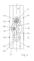
- the swivel bracket 13 also has a driver 18, the - As can be seen in particular from FIGS. 2a and 2b - with a Spring element 17 is operatively connected via an opening 26.
- the outer contour 23 of the spring element 17 has - in plan view seen - arched structure, generally with the reference number 24 is designated.
- the spring element 17 has two opposite Arranged arches 241 and 242, which are arch extensions 27a and 27b are formed, by means of which the spring element 17 in the longitudinal slot 14 of the faceplate 15 is guided longitudinally.
- the bulges 19a and 19b are in the Longitudinal slot 14 arranged at the point where a tilt is desired.
- the driver 18 pivots Swivel bracket 13 the middle region of the arched structure 24 in the direction of the bulge 19a, since the locking member 10 of the Swivel tab 13 engages in the bolt link pocket 16 and therefore relative to the faceplate 15, the drive rod 12 and Toggle lock plate 7 for a limited swivel range is deflectable.
- the swivel tab is only in this position released for this movement.
- Figure 4a is a first embodiment of the spring element 17 shown in the untensioned position.
- the Spring element 17 has a slot 25 in the center.
- FIG. 4b shows only the one facing the bulge Part deflected by the driver 18.
- a second embodiment of the spring element 17 for larger spring forces are shown in Figure 5.
- the driver 18 is completely enclosed here by the spring element 17. In order to is achieved that the entire arched structure 24 am Suspension process participates.
- Figure 6 is a third embodiment of the spring element 17 shown, in which - especially from Figure 6c can be seen - the cross section is L-shaped, with an L-leg on the top of the faceplate 15 between this and the swivel bracket 13 is arranged what Wear significantly counteracts when the spring element consists of a low-friction polymer material.
- the outer contour of the spring element 17 can along its outer contour 23 closed all round or - as in FIG. 7 and 8 - be interrupted on one side, the Bearing pin 11 penetrates the remaining arch 241.
- the spring element 17 shown in FIG. 8 of a sixth Embodiment runs in the area of the interruption of the arched structure 24 with an arch 242 then another sheet 243. Both the opposite outlines of arc 242 as well of the arc 243 are tangent to the longitudinal edges 14a and 14b of the longitudinal slot 14 of the faceplate 15.
- the cross section of the Spring element 17 as in FIG. 9a largely rectangular, Cross section 28a, round cross section 28b and according to FIG. 9b 9c oval cross section 28c or, as above described, and shown in detail in Figure 9d, L-shaped Have cross section 28d.
- Cross section 28a largely rectangular, Cross section 28a, round cross section 28b and according to FIG. 9b 9c oval cross section 28c or, as above described, and shown in detail in Figure 9d, L-shaped Have cross section 28d.
- the spring element 17 can be stiffened along the Structure encircling embeddings 29 - e.g. made of aramid - be provided, as indicated in Figure 9a.
- FIG 10 are the three switching position of a lever 30 and in Figure 11 the corresponding positions of the swivel bracket 13 and the associated spring member 17 of the rocker bar device normal switching sequence shown schematically.
- the lever 30 In the with V designated locking position, the lever 30 is in downward swung position.
- the lever is about one usual - and therefore not shown - linkage with the Tilt lock device connected to the drive rod acts axially displacing.
- the Closed position representing position at the top of the Longitudinal slot 14 of the faceplate 15.
- the locking pin 31 rests between the two, as described above Locking webs 32 of the toggle plate 7.
- the rotary position marked D is reached, at which the Wing 2 can be rotated about its pivot axis.
- the Rotational movement is based on the linkage, not shown transfer the drive rod and the swivel bracket 13 along with the, around the bearing pin 11 engaging spring element 17 in a with respect to the longitudinal slot 14 middle position axially implemented, the locking pin 32 the area of has left two locking webs 32 so that the Locking released and an unimpeded turning of the Wing around its fishing axis is possible.
- the longitudinal slot 14 has in this area the bulges 19a and 19b, so that the Tilt the wing 2 the swivel tab on one of the Bolt link webs 5a, 5b supporting against that of the Driver 18 deformed spring element 17, wherein the the area of the spring element 17 surrounding the driver 18 is deflected and into one of the bulges 19a, 19b immersed.
- the Wing on the lower frame corner 3.
- FIG. 12 shows the so-called tbt switching sequence of the lever 30 and in Figure 13 shows the corresponding positions of the Swivel tab 13 and the spring element 17 shown.
- the one with V marked locking position is the above described the same.
- the lever 30 from the lower closed position by 90 ° in Tilted counterclockwise is the tilt position set.
- the pivoting movement acts as above described on the swivel bracket 13 and the spring element 17th such that it covers the central region of the longitudinal slot 14 reached, the locking pin 31 the area of the two Locking webs 32 has left, so that the locking lifted and an unimpeded tipping of the wing he follows.
- the locking member 10 engages in the tilt lock plate side Bolt links 5a and 5b, which are now in the middle Area of the tilt lock plate are arranged.
Landscapes
- Engineering & Computer Science (AREA)
- Mechanical Engineering (AREA)
- Lock And Its Accessories (AREA)
- Window Of Vehicle (AREA)
- Closing And Opening Devices For Wings, And Checks For Wings (AREA)
Applications Claiming Priority (2)
| Application Number | Priority Date | Filing Date | Title |
|---|---|---|---|
| DE19821129 | 1998-05-12 | ||
| DE19821129A DE19821129C1 (de) | 1998-05-12 | 1998-05-12 | Kippriegelvorrichtung |
Publications (2)
| Publication Number | Publication Date |
|---|---|
| EP0957224A1 true EP0957224A1 (fr) | 1999-11-17 |
| EP0957224B1 EP0957224B1 (fr) | 2002-03-27 |
Family
ID=7867454
Family Applications (1)
| Application Number | Title | Priority Date | Filing Date |
|---|---|---|---|
| EP99103823A Expired - Lifetime EP0957224B1 (fr) | 1998-05-12 | 1999-02-27 | Dispositif de blocage en basculement |
Country Status (4)
| Country | Link |
|---|---|
| EP (1) | EP0957224B1 (fr) |
| AT (1) | ATE215170T1 (fr) |
| DE (2) | DE19821129C1 (fr) |
| PL (1) | PL333049A1 (fr) |
Cited By (1)
| Publication number | Priority date | Publication date | Assignee | Title |
|---|---|---|---|---|
| EP1498563A1 (fr) * | 2003-07-15 | 2005-01-19 | Gretsch-Unitas GmbH Baubeschlagfabrik | Dispositif pour creer une fente d'aeration |
Families Citing this family (2)
| Publication number | Priority date | Publication date | Assignee | Title |
|---|---|---|---|---|
| BE1032276B1 (nl) * | 2023-12-22 | 2025-07-23 | Sobinco Fa | Beslag voor een raam |
| EP4644649A1 (fr) * | 2024-05-03 | 2025-11-05 | Masterlab S.R.L. | Accessoire pour portes ou fenêtres oscillo-battantes |
Citations (1)
| Publication number | Priority date | Publication date | Assignee | Title |
|---|---|---|---|---|
| DE3627043C1 (de) | 1986-08-09 | 1987-10-08 | Siegenia Frank Kg | Kippriegelvorrichtung fuer Drehkippfluegel-Fenster und-Tueren od.dgl. |
Family Cites Families (1)
| Publication number | Priority date | Publication date | Assignee | Title |
|---|---|---|---|---|
| DE4203909C2 (de) * | 1992-02-11 | 1995-03-23 | Bilstein August Gmbh Co Kg | Kippriegelvorrichtung |
-
1998
- 1998-05-12 DE DE19821129A patent/DE19821129C1/de not_active Expired - Fee Related
-
1999
- 1999-02-27 AT AT99103823T patent/ATE215170T1/de not_active IP Right Cessation
- 1999-02-27 DE DE59901040T patent/DE59901040D1/de not_active Expired - Fee Related
- 1999-02-27 EP EP99103823A patent/EP0957224B1/fr not_active Expired - Lifetime
- 1999-05-11 PL PL99333049A patent/PL333049A1/xx unknown
Patent Citations (1)
| Publication number | Priority date | Publication date | Assignee | Title |
|---|---|---|---|---|
| DE3627043C1 (de) | 1986-08-09 | 1987-10-08 | Siegenia Frank Kg | Kippriegelvorrichtung fuer Drehkippfluegel-Fenster und-Tueren od.dgl. |
Cited By (1)
| Publication number | Priority date | Publication date | Assignee | Title |
|---|---|---|---|---|
| EP1498563A1 (fr) * | 2003-07-15 | 2005-01-19 | Gretsch-Unitas GmbH Baubeschlagfabrik | Dispositif pour creer une fente d'aeration |
Also Published As
| Publication number | Publication date |
|---|---|
| DE19821129C1 (de) | 1999-10-21 |
| EP0957224B1 (fr) | 2002-03-27 |
| DE59901040D1 (de) | 2002-05-02 |
| ATE215170T1 (de) | 2002-04-15 |
| PL333049A1 (en) | 1999-11-22 |
Similar Documents
| Publication | Publication Date | Title |
|---|---|---|
| DE2920581C3 (de) | Zusatzverriegelung, insbesondere Mittelverriegelung, für Fenster, Türen od.dgl. | |
| EP0646690B1 (fr) | Dispositif d'arrêt pour maintenir un élément de fermeture | |
| EP1460211A2 (fr) | Serrure de véhicule automobile | |
| EP0496039A1 (fr) | Serrure de portière pour véhicule automobile | |
| DE102005030699A1 (de) | Türfeststeller für Kraftfahrzeuge | |
| EP0914534A1 (fr) | Coin de verrouillage pour serrure de portiere de vehicule automobile ou analogue, et serrure de portiere de vehicule automobile pourvue d'un tel coin de verrouillage | |
| EP1803878A2 (fr) | Fermeture de décompression | |
| EP2338715B1 (fr) | Porte coulissante pour véhicule | |
| AT511249B1 (de) | Schiebetür für ein fahrzeug | |
| EP2329976B1 (fr) | Porte coulissante pour véhicule | |
| EP1794399B1 (fr) | Verrouillage de plancher | |
| EP3175068B1 (fr) | Système de ferrure | |
| DE202005000064U1 (de) | Band für eine verdeckte Anordnung zwischen Zarge und Flügel | |
| EP0957224B1 (fr) | Dispositif de blocage en basculement | |
| DE202006005103U1 (de) | Verstellsystem für einen Fahrzeugsitz | |
| DE3844995C2 (de) | Feststellvorrichtung für eine mit einem Türschließer versehene Tür | |
| EP1147278A1 (fr) | Dispositif de fermeture pour battants a croisement de fenetres, de portes ou similaires, sans montants, a deux battants | |
| EP1788175A1 (fr) | Assemblage de pattes pour fenêtres, portes et similaires | |
| DE3741386A1 (de) | Federnde scharnieranordnung fuer schwenktueren, insbesondere fuer automobiltueren | |
| DE102012010438B4 (de) | Türöffner mit Sperr-Riegel | |
| EP3543444B1 (fr) | Palier pour un dispositif de ferrure d'une fenêtre | |
| EP3339544B1 (fr) | Armature basculante pour un vantail de fenêtre ou de porte | |
| DE102024125712A1 (de) | Ausstellschere für eine Gebäudeverschlusseinrichtung sowie entsprechende Gebäudeverschlusseinrichtung | |
| EP1936085B1 (fr) | Armatures pour fenêtres, portes ou analogues | |
| EP2335957B1 (fr) | Porte coulissante pour véhicule |
Legal Events
| Date | Code | Title | Description |
|---|---|---|---|
| PUAI | Public reference made under article 153(3) epc to a published international application that has entered the european phase |
Free format text: ORIGINAL CODE: 0009012 |
|
| AK | Designated contracting states |
Kind code of ref document: A1 Designated state(s): AT BE CH DE DK ES FR GB IT LI NL |
|
| AX | Request for extension of the european patent |
Free format text: AL;LT;LV;MK;RO;SI |
|
| 17P | Request for examination filed |
Effective date: 19991202 |
|
| AKX | Designation fees paid |
Free format text: AT BE CH DE DK ES FR GB IT LI NL |
|
| GRAG | Despatch of communication of intention to grant |
Free format text: ORIGINAL CODE: EPIDOS AGRA |
|
| GRAG | Despatch of communication of intention to grant |
Free format text: ORIGINAL CODE: EPIDOS AGRA |
|
| 17Q | First examination report despatched |
Effective date: 20001124 |
|
| GRAG | Despatch of communication of intention to grant |
Free format text: ORIGINAL CODE: EPIDOS AGRA |
|
| GRAH | Despatch of communication of intention to grant a patent |
Free format text: ORIGINAL CODE: EPIDOS IGRA |
|
| GRAH | Despatch of communication of intention to grant a patent |
Free format text: ORIGINAL CODE: EPIDOS IGRA |
|
| REG | Reference to a national code |
Ref country code: GB Ref legal event code: IF02 |
|
| GRAA | (expected) grant |
Free format text: ORIGINAL CODE: 0009210 |
|
| AK | Designated contracting states |
Kind code of ref document: B1 Designated state(s): AT BE CH DE DK ES FR GB IT LI NL |
|
| PG25 | Lapsed in a contracting state [announced via postgrant information from national office to epo] |
Ref country code: NL Free format text: LAPSE BECAUSE OF FAILURE TO SUBMIT A TRANSLATION OF THE DESCRIPTION OR TO PAY THE FEE WITHIN THE PRESCRIBED TIME-LIMIT Effective date: 20020327 Ref country code: IT Free format text: LAPSE BECAUSE OF FAILURE TO SUBMIT A TRANSLATION OF THE DESCRIPTION OR TO PAY THE FEE WITHIN THE PRESCRIBED TIME-LIMIT;WARNING: LAPSES OF ITALIAN PATENTS WITH EFFECTIVE DATE BEFORE 2007 MAY HAVE OCCURRED AT ANY TIME BEFORE 2007. THE CORRECT EFFECTIVE DATE MAY BE DIFFERENT FROM THE ONE RECORDED. Effective date: 20020327 |
|
| REF | Corresponds to: |
Ref document number: 215170 Country of ref document: AT Date of ref document: 20020415 Kind code of ref document: T |
|
| REG | Reference to a national code |
Ref country code: CH Ref legal event code: EP |
|
| REG | Reference to a national code |
Ref country code: CH Ref legal event code: NV Representative=s name: PA ALDO ROEMPLER |
|
| GBT | Gb: translation of ep patent filed (gb section 77(6)(a)/1977) |
Effective date: 20020327 |
|
| REF | Corresponds to: |
Ref document number: 59901040 Country of ref document: DE Date of ref document: 20020502 |
|
| PG25 | Lapsed in a contracting state [announced via postgrant information from national office to epo] |
Ref country code: DK Free format text: LAPSE BECAUSE OF FAILURE TO SUBMIT A TRANSLATION OF THE DESCRIPTION OR TO PAY THE FEE WITHIN THE PRESCRIBED TIME-LIMIT Effective date: 20020627 |
|
| ET | Fr: translation filed | ||
| NLV1 | Nl: lapsed or annulled due to failure to fulfill the requirements of art. 29p and 29m of the patents act | ||
| PG25 | Lapsed in a contracting state [announced via postgrant information from national office to epo] |
Ref country code: ES Free format text: LAPSE BECAUSE OF FAILURE TO SUBMIT A TRANSLATION OF THE DESCRIPTION OR TO PAY THE FEE WITHIN THE PRESCRIBED TIME-LIMIT Effective date: 20020925 |
|
| PLBE | No opposition filed within time limit |
Free format text: ORIGINAL CODE: 0009261 |
|
| STAA | Information on the status of an ep patent application or granted ep patent |
Free format text: STATUS: NO OPPOSITION FILED WITHIN TIME LIMIT |
|
| PG25 | Lapsed in a contracting state [announced via postgrant information from national office to epo] |
Ref country code: GB Free format text: LAPSE BECAUSE OF NON-PAYMENT OF DUE FEES Effective date: 20030227 Ref country code: AT Free format text: LAPSE BECAUSE OF NON-PAYMENT OF DUE FEES Effective date: 20030227 |
|
| PG25 | Lapsed in a contracting state [announced via postgrant information from national office to epo] |
Ref country code: LI Free format text: LAPSE BECAUSE OF NON-PAYMENT OF DUE FEES Effective date: 20030228 Ref country code: CH Free format text: LAPSE BECAUSE OF NON-PAYMENT OF DUE FEES Effective date: 20030228 Ref country code: BE Free format text: LAPSE BECAUSE OF NON-PAYMENT OF DUE FEES Effective date: 20030228 |
|
| 26N | No opposition filed |
Effective date: 20021230 |
|
| PG25 | Lapsed in a contracting state [announced via postgrant information from national office to epo] |
Ref country code: DE Free format text: LAPSE BECAUSE OF NON-PAYMENT OF DUE FEES Effective date: 20030902 |
|
| GBPC | Gb: european patent ceased through non-payment of renewal fee | ||
| REG | Reference to a national code |
Ref country code: CH Ref legal event code: PL |
|
| PG25 | Lapsed in a contracting state [announced via postgrant information from national office to epo] |
Ref country code: FR Free format text: LAPSE BECAUSE OF NON-PAYMENT OF DUE FEES Effective date: 20031031 |
|
| REG | Reference to a national code |
Ref country code: FR Ref legal event code: ST |