EP0957251A2 - Lufteinlassvorrichtung für Brennkraftmaschine - Google Patents
Lufteinlassvorrichtung für Brennkraftmaschine Download PDFInfo
- Publication number
- EP0957251A2 EP0957251A2 EP99106237A EP99106237A EP0957251A2 EP 0957251 A2 EP0957251 A2 EP 0957251A2 EP 99106237 A EP99106237 A EP 99106237A EP 99106237 A EP99106237 A EP 99106237A EP 0957251 A2 EP0957251 A2 EP 0957251A2
- Authority
- EP
- European Patent Office
- Prior art keywords
- air intake
- internal combustion
- drive shaft
- combustion engine
- rotating shaft
- Prior art date
- Legal status (The legal status is an assumption and is not a legal conclusion. Google has not performed a legal analysis and makes no representation as to the accuracy of the status listed.)
- Withdrawn
Links
Images


Classifications
-
- F—MECHANICAL ENGINEERING; LIGHTING; HEATING; WEAPONS; BLASTING
- F02—COMBUSTION ENGINES; HOT-GAS OR COMBUSTION-PRODUCT ENGINE PLANTS
- F02D—CONTROLLING COMBUSTION ENGINES
- F02D9/00—Controlling engines by throttling air or fuel-and-air induction conduits or exhaust conduits
- F02D9/08—Throttle valves specially adapted therefor; Arrangements of such valves in conduits
- F02D9/12—Throttle valves specially adapted therefor; Arrangements of such valves in conduits having slidably-mounted valve members; having valve members movable longitudinally of conduit
- F02D9/16—Throttle valves specially adapted therefor; Arrangements of such valves in conduits having slidably-mounted valve members; having valve members movable longitudinally of conduit the members being rotatable
-
- F—MECHANICAL ENGINEERING; LIGHTING; HEATING; WEAPONS; BLASTING
- F02—COMBUSTION ENGINES; HOT-GAS OR COMBUSTION-PRODUCT ENGINE PLANTS
- F02D—CONTROLLING COMBUSTION ENGINES
- F02D9/00—Controlling engines by throttling air or fuel-and-air induction conduits or exhaust conduits
- F02D9/08—Throttle valves specially adapted therefor; Arrangements of such valves in conduits
- F02D9/10—Throttle valves specially adapted therefor; Arrangements of such valves in conduits having pivotally-mounted flaps
- F02D9/107—Manufacturing or mounting details
-
- F—MECHANICAL ENGINEERING; LIGHTING; HEATING; WEAPONS; BLASTING
- F05—INDEXING SCHEMES RELATING TO ENGINES OR PUMPS IN VARIOUS SUBCLASSES OF CLASSES F01-F04
- F05C—INDEXING SCHEME RELATING TO MATERIALS, MATERIAL PROPERTIES OR MATERIAL CHARACTERISTICS FOR MACHINES, ENGINES OR PUMPS OTHER THAN NON-POSITIVE-DISPLACEMENT MACHINES OR ENGINES
- F05C2201/00—Metals
- F05C2201/02—Light metals
- F05C2201/021—Aluminium
Definitions
- the present invention relates to an air intake apparatus for an internal combustion engine and in particular to an air intake apparatus for an internal combustion engine wherein a rotation force transmission structure to an opening and closing valve of an air intake apparatus.
- an opening and closing valve is provided at a midway of an air intake conduit, when an internal combustion engine rotates at a low speed rotation, by closing the opening and closing valve a length of the air intake conduit is made long and then an output torque during the low speed rotation of the internal combustion engine is heightened.
- the length of the air intake conduit or the flow passage cross-sectional area is varied. And to vary the length of the air intake conduit or to vary the flow passage cross-section area, a butterfly shape valve or a cylindrical shape opening and closing valve is used.
- the butterfly shape valve comprises a flat plate shape valve main body and a rotating shaft and the valve main body and the rotating shaft are manufactured separately or independently and this valve main body and this rotating shaft are combined with screw members etc..
- the rotating shaft has a long and slender rod shape, to this rotating shaft plural butterfly shape valves are installed.
- not only bearing member is provided to both ends of the rotating shaft but also a bearing member is provided between the butterfly shape valve and the another butterfly shape valve.
- an opening portion which penetrates to a radial direction of a cylinder is provided on the cylindrical shape opening and closing valve, a valve portion is constituted by the opening portion and another portion except for the opening portion. By rotating this opening portion, the intake air which passes through the opening portion is discontinued.
- one end of a cylindrical shape opening and closing valve is contacted to a small hole portion which is provided at a bottom of a hole portion and also using a spring member the cylindrical shape opening and closing valve is added with an axial direction force to come off from this small hole portion of the cylindrical shape opening and closing valve.
- An object of the present invention resides in that, the problems which have not been solved in the prior arts can be solved, namely when an inclination exists between an axial direction of a rotating shaft for rotating a cylindrical shape opening and closing valve and an axial direction of a drive shaft a rotating motion can be transmitted smoothly, and the object of the present invention to provide an air intake apparatus for an internal combustion engine wherein a simple construction, an easy manufacturing, a low cost air intake apparatus for the internal combustion engine can be provided.
- Another object of the present invention is to provide an air intake apparatus for an internal combustion engine wherein a durability in the air intake apparatus can be heightened by carrying out a position regulation against to a thrust direction of a drive shaft.
- a sphere portion which is provided at a tip end portion of a shaft portion of one of the rotating shaft and the drive shaft or an input shaft (in this application, it is called as the drive shaft) is inserted to a cup member which is provided at a tip end portion of another shaft of one of the rotating shaft and the drive shaft, and a projection portion of one of the rotating shaft and the drive shaft is engaged with a faucet portion which is provided at the tip end portion of the another shaft of the rotating shaft and the drive shaft and then a universal joint is constituted. According to these constructions, a welding working and a shaving-off working can be became unnecessary.
- a position regulation of a thrust direction of the drive shaft is attained that the drive shaft and a ball bearing member are inserted under pressure and fixed, and after the ball bearing member has inserted to a resin housing, in accordance with a stopping operation due to a spring force by a stopper ring and a bite-in of the stopper ring to the resin housing, then the ball bearing member is fixed to the resin housing.
- the stopper ring having the spring operation the ball bearing member can be fixed to the resin housing.
- the present invention can provide following air intake apparatus apparatuses for the internal combustion engine.
- an air intake apparatus for an internal combustion engine comprises an opening and closing valve for shielding the air intake supplied to an internal combustion engine, a rotating shaft installed to the opening and closing valve as one body, a drive shaft for rotating the rotating shaft, a connection portion for connecting the rotating shaft and the drive shaft and for transmitting a move from the drive shaft to the rotating shaft.
- the air intake apparatus for the internal combustion eigne wherein on an end portion of one of the rotating shaft and the drive shaft, a sphere portion and a projection portion are formed, on another end portion of one of the rotating shaft and the drive shaft, a cup portion and a faucet portion are formed, and the sphere portion is inserted into the cup portion and further the projection portion is engaged with the faucet portion, thereby a universal joint is formed.
- an inner portion of the above stated faucet portion is formed with a dent shape, and further an outer portion of the above stated projection portion is formed with a raise portion.
- the above stated drive shaft is provided in the resin housing, and to the above stated drive shaft a ball bearing member is fixed, and to the resin housing a part of the ball bearing member is stopped, and further the ball bearing member is fixed to the above stated resin housing by a stopper ring having a spring operation.
- the present invention provides an air intake apparatus for an internal combustion engine in which the above stated drive shaft is provided in the resin housing, a shaft portion of the above stated opening and closing valve and the above stated drive shaft are connected with a universal joint construction, to the above stated drive shaft a ball bearing member is fixed, and to the above stated resin housing a part of the ball bearing member is stopped, and further the above stated ball bearing member is fixed to the above stated resin housing by a stopper ring having a spring operation.
- an air intake apparatus for an internal combustion eigne of one embodiment (the first embodiment) according to the present invention an air intake apparatus for a spark ignition system internal combustion engine which uses the fuel such as the gasoline is exemplified, however the present invention can be applied to the air intake apparatuses for other internal combustion engines such a self ignition system internal combustion engine, etc..
- FIG. 1 shows a detailed cross-sectional view showing an air intake apparatus for an internal combustion engine of one embodiment (the first embodiment) which guides the air intake for supplying to the internal combustion engine (not shown in figure)
- Fig. 2 shows a perspective view of a component construction of the air intake apparatus for the internal combustion engine shown in Fig. 1.
- the air intake apparatus for the internal combustion engine comprises mainly an air intake conduit and the air intake conduit for guiding the air intake which is inhaled to the internal combustion engine.
- An injector is installed to the air intake conduit and the injector supplies the fuel to a combustion chamber of a respective cylinder of the internal combustion engine.
- a fuel conduit is installed to the injector and the fuel is supplied to the combustion chamber of the internal combustion engine.
- the above stated air intake conduit of the internal combustion engine comprises a collector comprised of one chamber, branches having same number air intake passages to a number of cylinders of the internal combustion engine, a flange for combining with a throttle valve opening and closing valve which adjusts an amount of the air intake, and another flange for combining an internal combustion engine block and those above stated elements are manufactured integrally.
- FIG. 1 A construction of an opening and closing valve 1 of the air intake apparatus for the internal combustion engine will be explained referring to Fig. 1 and Fig. 2.
- An essential construction of the opening and closing valve 1 in the air intake apparatus for the internal combustion engine have a valve body portion 11, a rotating shaft 12, and a valve holder 3.
- the valve body portion 11 has a flat plate shape and further the rotating shaft 12 has a round rod shape. Since each of the valve body portion 11 and the rotating shaft 12 has a simple shape, the valve body portion 11 and the rotating shaft 12 can be manufactured integrally and easily.
- each of the materials for the valve body portion 11 and the rotating shaft 12 of the air intake apparatus can employ a synthetic resin and are can be made according to an integral transformation process or can be manufactured according to an integral casting process or a forging process using a light alloy metal such as an aluminum alloy metal.
- the valve body portion 11 and the rotating shaft 12 can be formed respectively using a separate material or an individual material.
- a pair of sealing portions 13 are formed to a peripheral direction with a respective above stated air intake branches 13 and to a groove 14 which is formed at an intermediate portion of the pair of sealing portions 13 a sealing ring 15 is fitted into.
- This sealing ring 15 is fitted into rotatively against a rotation direction of the valve body portion 11 of the opening and closing valve 1.
- a material for the sealing ring 15 is established by taking into the consideration of a sliding performance.
- the sealing ring 15 works a role of a sealing operation of the intake air together with an inner face of the valve holder 3.
- a sphere shape portion 16 is formed at a tip end portion of the rotating shaft 12 and further a projection portion 17 is formed integrally.
- the projection portion 17 has a shape to which a part of the sphere shape portion 16 is projected.
- a hole portion 18 is formed to a center portion of a shaft portion to which the sphere shape portion 16 is provided and to this hole portion 18 a spring member 29 as stated in a latter is inserted.
- the valve holder 3 is formed with a resin housing 4 as one body.
- a drive shaft 2 is provided in a drive shaft use hole portion 41 which is arranged to the resin housing 4.
- a ball bearing member 20 is inserted under pressure and fixed to the drive shaft 2 and to the resin housing 4 the ball bearing member 20 is inserted and fixed.
- a stopper ring 24 is provided at a left end side of the ball bearing member 20.
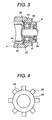
- This stopper ring 24, as shown in Fig. 4, is comprised of a thin single plate 26 which is manufactured by a punching-out process, and at a periphery portion of the stopper ring 24 plural projection portions 25 having a gear shape are formed and this projection portion 25 has a spring operation.
- This stopper ring 24 is arranged as shown in Fig. 3.
- the ball bearing member 20 is inserted under pressure and fixed and another end of the drive shaft 2 is penetrated to a hole portion 26 which is provided on the stopper ring 24 and a cup member 22 is fixed to the drive shaft 2.
- the cup member 22 has a cup shape which is formed by an elastic processing using a pressing-out process and an inner diameter of the cup member 22 has substantially to an outer diameter of the above stated sphere shape portion 16.
- a faucet portion for example as shown in Fig. 2
- a cup raise portion 23 is formed at a part of the cup member 22 .
- An inner side of the cup raise portion 23 has a dent portion as shown in Fig. 2.
- the opening and closing valve 1 is moved to a right portion, as shown in an arrow mark a of Fig. 2, and the sphere portion 16 which is provided at the tip end portion of the above stated rotating shaft 12 is fitted into the cup member 22 and further the projection portion 17 is fitted into an inner face dent portion of the cup raise portion 23.
- a spring member 29 is arranged between the inner face of the cup member 22 and an inner portion hole 18 of the rotating shaft 12 and the spring member 29 prevents a jolt to a longitudinal direction of the opening and closing valve 1.
- the fixing manner between the drive shaft 2 and the cup member 22 can be fixed using screw members, and further the fixing can be fixed using an adhesion process, a pressure-in process and a welding method etc..
- a rotation input from an actuator 60 is transmitted to the drive shaft 2.
- the actuator 60 is comprised of an actuator 60 output rod 40, a cover member, a spring member, a diaphragm member, one diaphragm member receiver, and another diaphragm member receiver, etc. (not shown in figure).
- the actuator output rod 40 is made to move an input lever 50.
- a reference numeral 51 indicates an air-tight sealing use lip sealing.
- the input lever 50 has a function in which the rotation of the drive shaft 2 is stopped with a beforehand predetermined angle.
- Fig. 5 shows another universal joint for constituting a connection portion between the rotating shaft 12 and the drive shaft 2 of a second embodiment according to the present invention.
- the sphere shape portion 16 and the projection portion 17 are formed to the rotating shaft 12 and the cup member 22 and the cup raise portion 23 are formed to the drive shaft 2.
- the sphere shape portion 16 and the projection portion 17 can be formed to the drive shaft 2 and the cup member 22 and the cup raise portion 23 are formed to the rotating shaft 12.
- the sphere shape portion 16 and the projection portion 17 are formed with the resin material and the sphere shape portion 16 and the projection portion 17 can be fixed to the drive shaft 2.
- the above stated sphere shape portion 16 is received in a hole portion 61 which is provided in an interior portion of the rotating shaft 12.
- a spring member 29 is received in a hole portion 62 which is provided in an interior portion of the sphere shape portion 16 and then the pressure-in operation is generated between the rotating shaft 12 and the drive shaft 2.
- FIG. 6 is a perspective view showing an air intake apparatus construction for an internal combustion engine according to the present invention.
- an air intake apparatus construction 100 for an internal combustion engine comprises mainly a negative pressure module 101, four independent branching conduits 102, a collector 103, an air intake manifold 104, a fuel pipe 105, an injector 106, a fuel pressure regulator 107, a throttle valve chamber 108, and an actuator solenoid 109.
- the opening and closing shaft 1 the actuator 60, and the actuator solenoid 109 are installed.
- the universal operation can be displayed according to the simple construction and the easy manufacture construction. As a result, even the inclination exists between the axial direction of the rotating shaft and the axial direction of the drive shaft, the rotation transmission can be carried out smoothly with the low cost construction.
- the thrust direction regulation of the drive shaft can be attained by the simple construction, and the cost reduction of the air intake apparatus for the internal combustion engine can be obtained by the simple construction.
Landscapes
- Engineering & Computer Science (AREA)
- Chemical & Material Sciences (AREA)
- Combustion & Propulsion (AREA)
- Mechanical Engineering (AREA)
- General Engineering & Computer Science (AREA)
- Control Of Throttle Valves Provided In The Intake System Or In The Exhaust System (AREA)
- Characterised By The Charging Evacuation (AREA)
- Shafts, Cranks, Connecting Bars, And Related Bearings (AREA)
Applications Claiming Priority (2)
| Application Number | Priority Date | Filing Date | Title |
|---|---|---|---|
| JP10311098A JP3355568B2 (ja) | 1998-04-14 | 1998-04-14 | 内燃機関の吸気装置 |
| JP10311098 | 1998-04-14 |
Publications (2)
| Publication Number | Publication Date |
|---|---|
| EP0957251A2 true EP0957251A2 (de) | 1999-11-17 |
| EP0957251A3 EP0957251A3 (de) | 2000-05-24 |
Family
ID=14345482
Family Applications (1)
| Application Number | Title | Priority Date | Filing Date |
|---|---|---|---|
| EP99106237A Withdrawn EP0957251A3 (de) | 1998-04-14 | 1999-04-13 | Lufteinlassvorrichtung für Brennkraftmaschine |
Country Status (3)
| Country | Link |
|---|---|
| US (2) | US6196178B1 (de) |
| EP (1) | EP0957251A3 (de) |
| JP (1) | JP3355568B2 (de) |
Cited By (1)
| Publication number | Priority date | Publication date | Assignee | Title |
|---|---|---|---|---|
| DE202007013719U1 (de) * | 2007-10-01 | 2009-02-19 | Mann+Hummel Gmbh | Vorrichtung mit zwei eine gemeinsame Längsachse aufweisenden und miteinander verbundenen Kunststoff-Bauteilen |
Families Citing this family (6)
| Publication number | Priority date | Publication date | Assignee | Title |
|---|---|---|---|---|
| DE102004047180B4 (de) * | 2004-09-29 | 2014-07-17 | Robert Bosch Gmbh | Aufladeeinrichtung mit Laststeuerung an Verbrennungskraftmaschinen |
| JP4137866B2 (ja) * | 2004-10-20 | 2008-08-20 | アスモ株式会社 | モータ |
| KR100655608B1 (ko) | 2004-12-07 | 2006-12-08 | 현대자동차주식회사 | 소음저감을 위한 가변흡기시스템의 가변밸브 결합구조 |
| JP5029664B2 (ja) * | 2009-09-09 | 2012-09-19 | ブラザー工業株式会社 | 画像形成装置およびカートリッジ |
| JP5966876B2 (ja) * | 2012-11-19 | 2016-08-10 | アイシン精機株式会社 | 吸気制御弁 |
| US20160265446A1 (en) * | 2015-03-13 | 2016-09-15 | Ford Global Technologies, Llc | Bracket assembly for an intake manifold, the intake manifold and method of operating the same |
Citations (4)
| Publication number | Priority date | Publication date | Assignee | Title |
|---|---|---|---|---|
| JPS60224924A (ja) | 1984-04-20 | 1985-11-09 | Mazda Motor Corp | 多気筒エンジンの吸気装置 |
| JPH0681735A (ja) | 1992-08-31 | 1994-03-22 | Hitachi Ltd | 内燃機関の吸気装置 |
| JPH0681719A (ja) | 1992-08-31 | 1994-03-22 | Hitachi Ltd | 内燃機関の吸気装置 |
| JPH08170536A (ja) | 1994-07-05 | 1996-07-02 | Filterwerk Mann & Hummel Gmbh | 多シリンダ式内燃機関に用いられる吸気装置 |
Family Cites Families (17)
| Publication number | Priority date | Publication date | Assignee | Title |
|---|---|---|---|---|
| FR2108817B1 (de) * | 1970-10-08 | 1977-01-21 | Citroen Sa | |
| DE3241723A1 (de) * | 1982-11-11 | 1984-05-17 | Volkswagenwerk Ag, 3180 Wolfsburg | Drehschieberanordnung zur steuerung des ladungswechsels einer brennkraftmaschine |
| JPH03286125A (ja) * | 1990-03-31 | 1991-12-17 | Mazda Motor Corp | エンジンの吸気装置 |
| US5315969A (en) * | 1993-02-01 | 1994-05-31 | Macmillan Kevin M | Internal combustion engine with rotary valves |
| DE4314809B4 (de) * | 1993-05-05 | 2005-08-04 | Carl Freudenberg Kg | Ansaugrohr für eine Verbrennungskraftmaschine |
| DE4344504A1 (de) | 1993-12-24 | 1995-06-29 | Audi Ag | Saugrohranlage für eine Mehrzylinder-Brennkraftmaschine |
| KR200152903Y1 (ko) * | 1994-08-25 | 1999-08-02 | 정몽규 | 내연기관의 흡기조절장치 |
| FR2724418B1 (fr) * | 1994-09-09 | 1997-01-17 | Magneti Marelli France | Tubulure d'admission d'air a volets pivotants pour moteur a combustion interne |
| US5524579A (en) * | 1994-10-28 | 1996-06-11 | Eluchans; Alejandro | Air cooled rotary distribution valve for internal combustion engine |
| DE9419537U1 (de) * | 1994-12-06 | 1995-02-02 | Fa. J. Eberspächer, 73730 Esslingen | Abgasklappen-Anordnung |
| US5875758A (en) * | 1995-04-06 | 1999-03-02 | E. I. Du Pont De Nemours And Company | Resin air intake system provided with intake control valve |
| AUPN559395A0 (en) * | 1995-09-22 | 1995-10-19 | Smith, Brian | Rotary valve for an internal combustion engine |
| JP3304751B2 (ja) * | 1996-03-29 | 2002-07-22 | トヨタ自動車株式会社 | 内燃機関の吸気通路構造 |
| US5706775A (en) * | 1996-04-12 | 1998-01-13 | New Avenue Development Corp. | Rotary valve apparatus for internal combustion engines and methods of operating same |
| WO1998011336A1 (en) | 1996-09-13 | 1998-03-19 | Hitachi, Ltd. | Suction structure for internal combustion engines |
| DE19652053A1 (de) * | 1996-12-13 | 1998-04-02 | Daimler Benz Ag | Betätigungsgestänge für ein verstellbares Bauelement |
| JPH11294277A (ja) * | 1998-04-07 | 1999-10-26 | Sanshin Ind Co Ltd | エンジン |
-
1998
- 1998-04-14 JP JP10311098A patent/JP3355568B2/ja not_active Expired - Fee Related
-
1999
- 1999-04-13 EP EP99106237A patent/EP0957251A3/de not_active Withdrawn
- 1999-04-14 US US09/290,878 patent/US6196178B1/en not_active Expired - Fee Related
-
2000
- 2000-12-28 US US09/749,475 patent/US6520138B2/en not_active Expired - Fee Related
Patent Citations (4)
| Publication number | Priority date | Publication date | Assignee | Title |
|---|---|---|---|---|
| JPS60224924A (ja) | 1984-04-20 | 1985-11-09 | Mazda Motor Corp | 多気筒エンジンの吸気装置 |
| JPH0681735A (ja) | 1992-08-31 | 1994-03-22 | Hitachi Ltd | 内燃機関の吸気装置 |
| JPH0681719A (ja) | 1992-08-31 | 1994-03-22 | Hitachi Ltd | 内燃機関の吸気装置 |
| JPH08170536A (ja) | 1994-07-05 | 1996-07-02 | Filterwerk Mann & Hummel Gmbh | 多シリンダ式内燃機関に用いられる吸気装置 |
Cited By (1)
| Publication number | Priority date | Publication date | Assignee | Title |
|---|---|---|---|---|
| DE202007013719U1 (de) * | 2007-10-01 | 2009-02-19 | Mann+Hummel Gmbh | Vorrichtung mit zwei eine gemeinsame Längsachse aufweisenden und miteinander verbundenen Kunststoff-Bauteilen |
Also Published As
| Publication number | Publication date |
|---|---|
| US6520138B2 (en) | 2003-02-18 |
| JPH11294195A (ja) | 1999-10-26 |
| JP3355568B2 (ja) | 2002-12-09 |
| US6196178B1 (en) | 2001-03-06 |
| EP0957251A3 (de) | 2000-05-24 |
| US20010000573A1 (en) | 2001-05-03 |
Similar Documents
| Publication | Publication Date | Title |
|---|---|---|
| US5746190A (en) | EGR system using perpendicularly arranged control valve | |
| EP1270920B1 (de) | Schlepphebel für nockenbetätigtes Hubventil in einem Ansaugsystem einer Brennkraftmaschine | |
| US10539100B2 (en) | Valve device | |
| JPH08240123A (ja) | 吸込みシステム | |
| JP2011043218A (ja) | 流体制御弁 | |
| JP2011058536A (ja) | 流体制御弁およびその製造方法 | |
| US5681508A (en) | Diaphragm carburetor for an internal combustion engine | |
| US6520138B2 (en) | Air intake apparatus for internal combustion engine | |
| US7213557B2 (en) | Air intake control system | |
| US7552711B2 (en) | Intake control device for vehicle engine | |
| JP2593343B2 (ja) | エンジンにおける燃料ポンプ取付構造 | |
| US20150247465A1 (en) | Adjustment device for valve assembly | |
| WO1998011336A1 (en) | Suction structure for internal combustion engines | |
| JP3905560B2 (ja) | 内燃機関の吸気装置 | |
| JP2872584B2 (ja) | Egrバルブ | |
| JPS6323547Y2 (de) | ||
| JP2000136760A (ja) | 排気ガス還流装置 | |
| JP7492483B2 (ja) | 吸気制御装置 | |
| EP4506552A1 (de) | Drosselvorrichtung für brennkraftmaschine | |
| JPH0413382Y2 (de) | ||
| CN113396298B (zh) | 用于阀系统的适配器 | |
| JP2012172519A (ja) | フラップバルブ | |
| US11486276B2 (en) | Valve rotating device | |
| CN109578103B (zh) | 用于凸轮轴的止推装置及发动机 | |
| JP2008309102A (ja) | エンジンの吸気制御装置 |
Legal Events
| Date | Code | Title | Description |
|---|---|---|---|
| PUAI | Public reference made under article 153(3) epc to a published international application that has entered the european phase |
Free format text: ORIGINAL CODE: 0009012 |
|
| AK | Designated contracting states |
Kind code of ref document: A2 Designated state(s): DE GB IT |
|
| AX | Request for extension of the european patent |
Free format text: AL;LT;LV;MK;RO;SI |
|
| PUAL | Search report despatched |
Free format text: ORIGINAL CODE: 0009013 |
|
| AK | Designated contracting states |
Kind code of ref document: A3 Designated state(s): AT BE CH CY DE DK ES FI FR GB GR IE IT LI LU MC NL PT SE |
|
| AX | Request for extension of the european patent |
Free format text: AL;LT;LV;MK;RO;SI |
|
| 17P | Request for examination filed |
Effective date: 20001005 |
|
| AKX | Designation fees paid |
Free format text: DE GB IT |
|
| GRAH | Despatch of communication of intention to grant a patent |
Free format text: ORIGINAL CODE: EPIDOS IGRA |
|
| RIN1 | Information on inventor provided before grant (corrected) |
Inventor name: MUNAKATA, AKIHIRO Inventor name: NEMOTO, HIROYUKI Inventor name: YAMASHITA, MISTURU,WA-IN-KATSUTA 407 Inventor name: MINEGISHI, TERUHIKO |
|
| STAA | Information on the status of an ep patent application or granted ep patent |
Free format text: STATUS: THE APPLICATION IS DEEMED TO BE WITHDRAWN |
|
| 18D | Application deemed to be withdrawn |
Effective date: 20030715 |