EP0957332A2 - Koordinatenmessgerät in Brückenbauweise - Google Patents
Koordinatenmessgerät in Brückenbauweise Download PDFInfo
- Publication number
- EP0957332A2 EP0957332A2 EP99107602A EP99107602A EP0957332A2 EP 0957332 A2 EP0957332 A2 EP 0957332A2 EP 99107602 A EP99107602 A EP 99107602A EP 99107602 A EP99107602 A EP 99107602A EP 0957332 A2 EP0957332 A2 EP 0957332A2
- Authority
- EP
- European Patent Office
- Prior art keywords
- coordinate measuring
- support
- measuring device
- supports
- connector
- Prior art date
- Legal status (The legal status is an assumption and is not a legal conclusion. Google has not performed a legal analysis and makes no representation as to the accuracy of the status listed.)
- Granted
Links
Images


Classifications
-
- G—PHYSICS
- G01—MEASURING; TESTING
- G01B—MEASURING LENGTH, THICKNESS OR SIMILAR LINEAR DIMENSIONS; MEASURING ANGLES; MEASURING AREAS; MEASURING IRREGULARITIES OF SURFACES OR CONTOURS
- G01B5/00—Measuring arrangements characterised by the use of mechanical techniques
- G01B5/0011—Arrangements for eliminating or compensation of measuring errors due to temperature or weight
- G01B5/0014—Arrangements for eliminating or compensation of measuring errors due to temperature or weight due to temperature
-
- G—PHYSICS
- G01—MEASURING; TESTING
- G01B—MEASURING LENGTH, THICKNESS OR SIMILAR LINEAR DIMENSIONS; MEASURING ANGLES; MEASURING AREAS; MEASURING IRREGULARITIES OF SURFACES OR CONTOURS
- G01B5/00—Measuring arrangements characterised by the use of mechanical techniques
- G01B5/004—Measuring arrangements characterised by the use of mechanical techniques for measuring coordinates of points
- G01B5/008—Measuring arrangements characterised by the use of mechanical techniques for measuring coordinates of points using coordinate measuring machines
Definitions
- Our invention relates to a coordinate measuring machine in Bridge construction, in which a spanning the measurement support Bridge on two guides located to the side of the measuring support is led.
- Such bridge measuring devices have been known for a long time. They usually point to the side next to the measuring support compared to the measurement support increased side panels on which in horizontal direction a bridge spanning the measurement pad is guided flexibly. Along the bridge is a so-called cross slide in a second horizontal Coordinate direction guided movably, the cross slide in turn a quill in the third coordinate direction vertically movable leads. Located at the bottom of the quill there is a button with the one on the measuring pad clamped workpiece can be measured.
- Such bridge measuring devices have compared to other common Coordinate measuring devices, such as the portal measuring device or the stand measuring device has the particular advantage that essentially the guides clearly above the measuring support located so that the guides against contamination are relatively well protected. Coordinate measuring devices in Bridge construction are due to this property of the Construction forth especially for use under rough Environmental conditions, such as in manufacturing designed.
- the task is performed according to the characterizing part of the claim 1 solved.
- the basic idea of the invention is to be seen in the fact that the guides for guiding the bridge rest on supports that have a low coefficient of thermal expansion and the supports in at least one thermally insulating Support body are arranged.
- the supports with the low coefficient of thermal expansion can be achieved that even at large temperature differences in the room in which the Coordinate measuring device is set up, the differences of Changes in length of the different supports only very slight are, so that the guides are always almost horizontal stay aligned.
- the supports are additionally thermally insulating support bodies thermally insulated by the support body, which in particular a relatively slow warming up or cooling down of the coordinate measuring machine and thus small temperature differences of the supports has the consequence, so that the measurement errors are also thereby can be significantly reduced.
- the thermally insulating support body can consist of one Range of different materials.
- a granite block could be used.
- the support body made of one is particularly advantageous Mineral casting, such as concrete or in particular Made of polymer concrete.
- mineral casting shows next to its thermally insulating Property still has a number of other special features advantageous properties that are also used.
- mineral casting similar to a House installation, in the manufacture of the support body empty pipes are poured in which then electrical lines as well Compressed air lines can be laid in a very simple way can. It also shows mineral casting as well as in particular Polymer concrete has excellent vibration damping properties on, which of course is particularly advantageous to the Measuring accuracy and the measuring speed affect.
- supports There are basically a number of materials for the supports different materials possible. It could be so for example, supports made of CFRP tube, which one according to today's technology can already wrap in such a way that it a thermal coefficient of linear expansion of 0 ⁇ m / (° C m) has or for example from Zerodur, which also a very low coefficient of thermal expansion owns. However, it has been found that as a material, at least for parts of the supports Invar steel is advantageously used, for example one thermal expansion coefficient of approx. 1.5 ⁇ m / (° C m) having.
- the Support in a vertical direction opposite the support body be agile. This can be done by for example in a granite block as a supporting body Appropriate holes are provided in which the supports then be arranged in each case. If you use it especially Advantageous mineral casting, so you achieve mobility in vertical direction by the supports not directly in the Mineral casting, but first by putting a pipe for example round or square cross-section in the Mineral casting is poured and the supports then in one such pipe in the hardened mineral casting, that is Support body can be arranged.
- the Coordinate measuring device is therefore one at least one of the supports in the area of guidance over one Connect the connector to the support body, the connector being the Support movable vertically in relation to the Carrier connects and in at least one horizontal Direction immovably connects to the support body.
- the support remains opposite in the vertical direction the support body movable, while in at least one horizontal coordinate direction the lateral forces and the moments can be absorbed by the support body.
- Connectors are a number of different ones Solutions conceivable.
- a pin could be on the support be attached in a corresponding vertical aligned groove engages in the support body.
- the pen is with it vertically movable along the groove, while in the horizontal longitudinal direction the support rigidly with the Support body would be connected.
- The is particularly advantageous
- connectors as punched or flame cut and if necessary, correspondingly curved sheet metal, as shown in the following text will be described with reference to the figures.
- the supports sit particularly advantageously on a frame.
- the frame can be made of different materials exist, but should have a relatively high rigidity exhibit.
- the frame particularly advantageously has one high thermal conductivity, so that additional temperature differences between the individual supports relatively quickly can be compensated.
- the frame is advantageously made of a metal manufactured.
- a frame is particularly advantageous for this made of welded double-T steel girders.
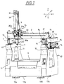
- FIG. 1 shows purely by way of example Embodiment for an inventive Coordinate measuring device in bridge construction.
- the coordinate measuring machine (1) has a substructure (42) that is purely external essentially one example of polymer concrete cast support body (5, 11, 12) with three areas, namely has the side parts (11 and 12) and the base part (5), which is mounted on the floor via dampers (13a-d).
- the center of the support body (5, 11, 12) is clean an example of a measuring support (6) in the form of a measuring table the workpiece to be measured, not shown here can be spanned.
- Supports arranged on which the guides (7, 8) attached are.
- the friction wheel drive (14) has essentially an electric motor that has a corresponding Friction wheel drives, which is directly on a tread (15) supported by a on the support body (5, 11, 12) tensioned band is formed, and thereby the bridge (2) actuation of the electric motor moves.
- an optically scannable, not visible scale provided by a on the holder (33) attached, also not visible optical here Readhead is scanned so that the exact position of the Bridge (2) in the direction of the guide (8) continuously detected and can be evaluated.
- the bridge (2) in a first horizontal Coordinate direction along the arrow (Y) the current position of the bridge (2) in the direction can be scanned.
- the cross slide (34) is not completely analogous here Air bearings, which can be seen closer, can be moved on the bridge (2) stored so that the cross slide (34) in a second horizontal direction, indicated here by the arrow (X) could be moved.
- the current position of the Cross slide (34) can be analogous to that on the bridge (2) attached scale (37) and on the cross slide (34) attached optical scanning head (40) are determined, wherein the cross slide (34) over one on the back of the bridge (2) arranged belt drive can be moved.
- the Quill (3) with an exemplary square cross section here again on all four outsides for a total of eight Air bearings (35a-d and 36a-d) (35c-d, 36c-d are not closed here see) movably mounted, the quill (3) over a Friction wheel drive (41) can be driven and the exact Position the sleeve by scanning the on the cross slide (34) attached scale (38) with the attached to the quill optical scanning head (39) can be done.
- the quill (3) can thus in the direction of the arrow labeled (Z) vertical and thus the third coordinate direction become.
- the measuring probe (43) can interchangeably accommodate the button (4).
- the measuring one Probe (43) can deflect the probe (4) in the three coordinate directions (X, Y, Z).
- the workpiece can thus be probed via the deflection of the Push button (4) from its rest position and above the on the scales sampled positions of the bridge mechanics in the three Coordinate directions (X, Y, Z) the exact location of a point to be scanned on the workpiece.
- the coordinate measuring machine shown in FIG I would like to explicitly mention again that this is of course purely exemplary.
- a switching probe can be used, in which a Probe pulse is generated as soon as the button (4) from its Rest position is deflected.
- a Probe pulse is generated as soon as the button (4) from its Rest position is deflected.
- it can also be one act optical probe.
- the drives or the bearings can vary in many ways. For example, instead of shown drives also spindle drives etc. or plain bearings, Rolling bearings etc. can be used.
- FIG. 2 shows a skeleton of the in Figure 1 shown coordinate measuring machine, in the essential Components, some of which are even entirely in the supporting body (5, 11, 12) are arranged according to Figure 1 can be seen.
- the guides (7, 8) lie on supports (17a-d) with the supports (17a-d) at their lower end
- the supports (17a-d) are tiltably mounted on a frame (16).
- the frame (16) consists of four double-T steel girders, which in their Contour welded into a corresponding rectangle were.
- the frame made in this way is, as already mentioned described, directly in the base part (5) of the support body (5, 11, 12) cast and serves to stiffen the Support body and in particular also about temperature differences compensate quickly between the supports (17a-d).
- the frame (16) for its part is an example of four common ones Vibration damper (13a-d) stored on the floor. Naturally can also use three vibration dampers or more than four Vibration dampers can be used alternatively.
- the supports (17a-d) point next to one further below described connector (20a-d) additional rods (18a-d) which can be tilted accordingly in the support bearings (19a-d) are stored.
- the supports (17a-d) point in here low thermal according to the invention Expansion coefficient, so that at Differences in temperature between the supports (17a-d) only small different linear expansions occur and the Guides (7, 8) even with larger ones Differences in temperature are aligned almost horizontally.
- the material is at least for the bars (18a-d) Invar steel with a thermal Expansion coefficients of approx. 1.5 ⁇ m / (° C m) particularly advantageous.
- FIG. 2 shows the skeleton in the supporting body (5, 11, 12) arranged, whereby the frame (16) completely in the lower Base part (5) of the supporting body (5, 11, 12) is cast in.
- the supports (17a-d) are not immediate poured into the supporting body (5, 11, 12), as this is vertical Direction, that is, the one designated by the arrow (Z) in FIG Direction with respect to the support body must be freely movable.
- the support body here was exemplary Polymer concrete (see above), as described below in 6 to 8 will be referred to in more detail, First cast a hollow tube (23a-d) in which the rods (18a-d) of the supports (17a-d) then after the completion of the Support body (5, 11, 12) can be installed.
- the connector (20a) Support (17a) is here via a two-part connector (21a 'and 21a' ') connected to the side part (11) in such a way that the connector (20a) of the support (17a) in vertical Direction, i.e. in the direction indicated by arrow (Z), movable relative to the side part (11) of the support body (5, 11, 12) is connected and at the same time the connector (20a) movable in the direction indicated by arrow (Y) the support body is connected.
- arrow (X) designated horizontal direction, however, this is from the support (17a) only visible connector (20a) immobile opposite the supporting body (5, 11, 12).
- Figure 5a shows a perspective view a part (21a ') of the two-part connector (21a' and 21a '').
- the assembly of the connector (21a 'and 21a' ') is done again can be seen from Figure 3 by the parts of the two-part Connector (21a 'and 21a' ') each via screws (55) the grooves (47) are screwed through to the connecting piece (20a) become.
- the parts of the connector become like this adjusts that the horizontal surfaces of the parts of the connector (21a 'and 21a' ') in the mm range opposite the support body are spaced.
- the parts of the connector each with screws (56) through the holes (48) on the support body (5, 11, 12) screwed tight so that due to the Spacing the parts of the connector (21a 'and 21a' ') in the Be biased like a leaf spring.
- the connector (21b) shows a second variant of a Connector, in which the connector (20b) both in the Arrow (X and Y) designated direction rigidly with the side part (12) of the support body (5, 11, 12) is connected.
- the connector (21b) only comprises a sheet in which two longitudinal grooves (44, 45), four holes (48) and a hole (49) was punched.
- the plate through screws (53) through the holes (48) Side part (11) of the support body (5, 11, 12) attached while the connector within the two grooves between the rod (17b) and the lower part (24b) of the connector (20b) through the screws (25b and 26b) is clamped (see FIG. 7 in advance).
- the hole (49) is a passage for the screws (25b, 26b) thought.
- the support (17b) and the support body (5, 11, 12) are here also dimensioned so spaced from one another that the connector (21b) when tightening the screws (53) - after the connector (21b) is attached to the support (17b) was tensioned - similar to a leaf spring.
- Figure 4 in turn shows the right side part (12) of the Support body (5, 11, 12).
- the only visible connector (20d) of the support (17d) with a connector identical to the connector (21a 'and 21a' ') (21d 'and 21d' '), and only visible here Connection piece (20c) of the support (17c) with one to the connector (21c) identical connector (21a) connected. So this is the connector (20d) and thus the support (17d) in the Arrow (Y and Z) designated moving direction with the Support body is connected while the support (17d) in the (X) designated direction rigidly with the side part (12) of the Carrying body (5, 11, 12) is connected.
- FIG. 6 shows a section of the skeleton shown in section in Figure 2, the cutout Support bearing (19b) includes. As can be seen here, that is Support bearing on the frame (16) and is via screws (51a, 51b) on the frame (16). Inside the Support bearing is provided a conical spherical cap on the the rounded end of the support (17b) or the rod (18b) lies on. About the support bearing designed in this way is the Support (17b) thus tiltably mounted on the frame (16) so that the support when mounting the coordinate measuring machine (17b) can be aligned until it is exactly vertical stands.
- the dampers (13a-d), the support bearings (19a-d) as well as the tubes (23a-d) can be arranged in the polymer concrete form to include the Pour supporting body.
- Figure 7 shows here a section through a section of the coordinate measuring machine (1) according to FIG. 1, with the connecting piece (20b) is cut.
- the Connection body (20b) a lower part (24b), an upper part (29b) and a between the lower part (24b) and upper part (29b) Ring (30b).
- Both the ring (30b) and the lower part (24b) are each provided with an inclined plane that rest on each other.
- the ring (30b) there are additional cut two threads into which the screws (27b and 28b) can intervene in each case.
- the screw axes can be adjusted.
- the ring is located (30b) more in the direction of the screw (27b), this lowers Upper part (29b) compared to the lower part (24b) due to the inclined plane accordingly.
- the lower part is on the screws (25b, 26b) on the Rod (18b) attached, between the lower part and rod (18b), as already explained above, the connector (21b) is clamped is.
- Figure 8 also shows a section through a section of the coordinate measuring machine (1) according to FIG. 1, in which the Connector (20b) is cut, the cut is rotated by 90 ° with respect to the illustration according to FIG. How from this, the ring (30b) actually lies here on the lower part (24b), the lower part (24b) only a groove in the middle for receiving the screws (25b, 26b) has in the area of the ring (30b) not on the Lower part (24b) rests.
- the ring (30b) can be tightened by the Screws (25b, 26b) are fixed.
- the remaining cavity in the connector (20b) even after the suitable adjustment of the ring (30b) through the filling opening (52) filled with an adhesive so that the selected one Setting is then fixed.
Landscapes
- Physics & Mathematics (AREA)
- General Physics & Mathematics (AREA)
- A Measuring Device Byusing Mechanical Method (AREA)
- Length Measuring Devices With Unspecified Measuring Means (AREA)
Abstract
Description
- Figur 1
- ein erfindungsgemäßes Koordinatenmeßgerät;
- Figur 2
- wesentliche Bauteile des Koordinatenmeßgerätes gemäß Figur 1 die größtenteils im Tragkörper (5, 11, 12) des Koordinatenmeßgerätes gemäß Figur 1 angeordnet sind;
- Figur 3
- Detailzeichnung des linken Seitenteils (11) des Tragkörpers (5, 11, 12) vom Koordinatenmeßgerät gemäß Figur 1;
- Figur 4
- Detailzeichnung des rechten Seitenteils (12) des Tragkörpers (5, 11, 12) vom Koordinatenmeßgerät gemäß Figur 1;
- Figur 5a
- Detailzeichnung eines Teils (21a') des Verbinders (21a' und 21a'');
- Figur 5b
- Detailzeichnung des Verbinders (21b);
- Figur 6
- Schnitt durch ein Stützenlager (19b) des Koordinatenmeßgerätes gemäß Figur 1;
- Figur 7
- Schnitt durch ein Anschlußstück (20b) des Koordinatenmeßgerätes gemäß Figur 1; und
- Figur 8
- Schnitt durch das Anschlußstück (20b) des Koordinatenmeßgerätes nach Figur 1 um 90 Grad gedreht gegenüber dem Schnitt nach Figur 7.
Claims (14)
- Koordinatenmeßgerät (1) in Brückenbauweise, bei dem eine die Meßauflage (6) überspannende Brücke (2) auf zwei seitlich der Meßauflage befindlichen Führungen (7, 8) geführt ist, dadurch gekennzeichnet, daß die Führungen (7, 8) auf Stützen (17a-d) aufliegen, die einen geringen thermischen Ausdehnungskoeffizienten aufweisen und die Stützen in wenigstens einem thermisch isolierenden Tragkörper (5, 11, 12) angeordnet sind.
- Koordinatenmeßgerät nach Anspruch 1, dadurch gekennzeichnet, daß wenigstens eine der Stützen im Bereich der Führung über einen Verbinder (21a' und 21a'', 21c, 21d' und 21d'') mit dem Tragkörper (5, 11, 12) verbunden ist, wobei der Verbinder (21a' und 21a'', 21c, 21d' und 21d'') die Stütze in vertikaler Richtung (Z) beweglich gegenüber dem Tragkörper verbindet und in wenigstens einer horizontalen Richtung (X) unbeweglich gegenüber dem Tragkärper verbindet.
- Koordinatenmeßgerät nach Anspruch 1, dadurch gekennzeichnet, daß wenigstens eine der Stützen an ihrem unteren Ende auf einem Rahmen (16) gelagert ist.
- Koordinatenmeßgerät nach Anspruch 1 oder 3, dadurch gekennzeichnet, daß wenigstens eine der Stützen über ein Stützenlager (19a-d) kippbar gelagert ist.
- Koordinatenmeßgerät nach Anspruch 4, dadurch gekennzeichnet, daß das Stützenlager eine kegelförmige Kalotte aufweist, auf der das abgerundete Ende der Stütze gelagert ist.
- Koordinatenmeßgerät nach Ansprüchen 3-5, dadurch gekennzeichnet, daß der Rahmen (16) aus Metall, sowie insbesondere aus Stahl gefertigt ist.
- Koordinatenmeßgerät nach Anspruch 1, dadurch gekennzeichnet, daß zumindest Teile der Stützen aus Invarstahl gefertigt sind.
- Koordinatenmeßgerät nach Anspruch 2, dadurch gekennzeichnet, daß der Verbinder ein gestanztes oder brenngeschnittenes Metallblech ist.
- Koordinatenmeßgerät nach Anspruch 3, dadurch gekennzeichnet, daß der Rahmen (16) über Dämpfer (13a-d) auf dem Boden gelagert ist.
- Koordinatenmeßgerät nach Anspruch 1, dadurch gekennzeichnet, daß wenigstens eine der Stützen über eine Höhenverstellung (27b, 28b, 30b) höhenverstellbar ist.
- Koordinatenmeßgerät nach Anspruch 10, dadurch gekennzeichnet, daß die Höhenverstellung einen verstellbaren Keil aufweist.
- Koordinatenmeßgerät nach Anspruch 1, dadurch gekennzeichnet, daß die Stützen in je einem Rohr (23a-d) im Tragkörper angeordnet sind.
- Koordinatenmeßgerät nach Anspruch 1 bis 12, dadurch gekennzeichnet, daß der Tragkörper (5,11,12) aus Mineralguß, sowie insbesondere aus Polymerbeton hergestellt ist.
- Koordinatenmeßgerät nach Anspruch 13, dadurch gekennzeichnet, daß der Rahmen (16) im Tragkörper (5, 11, 12) eingegossen ist.
Applications Claiming Priority (2)
| Application Number | Priority Date | Filing Date | Title |
|---|---|---|---|
| DE19821274A DE19821274A1 (de) | 1998-05-13 | 1998-05-13 | Koordinatenmeßgerät in Brückenbauweise |
| DE19821274 | 1998-05-13 |
Publications (3)
| Publication Number | Publication Date |
|---|---|
| EP0957332A2 true EP0957332A2 (de) | 1999-11-17 |
| EP0957332A3 EP0957332A3 (de) | 2001-04-25 |
| EP0957332B1 EP0957332B1 (de) | 2008-08-20 |
Family
ID=7867532
Family Applications (1)
| Application Number | Title | Priority Date | Filing Date |
|---|---|---|---|
| EP99107602A Expired - Lifetime EP0957332B1 (de) | 1998-05-13 | 1999-04-16 | Koordinatenmessgerät in Brückenbauweise |
Country Status (4)
| Country | Link |
|---|---|
| US (1) | US6161298A (de) |
| EP (1) | EP0957332B1 (de) |
| JP (1) | JP4383580B2 (de) |
| DE (2) | DE19821274A1 (de) |
Cited By (7)
| Publication number | Priority date | Publication date | Assignee | Title |
|---|---|---|---|---|
| WO2008056244A3 (en) * | 2006-11-10 | 2008-07-10 | Hexagon Metrology Spa | Beam for a co-ordinate measuring machine, method for its production, and measuring machine provided with said beam |
| EP1335180A3 (de) * | 2002-02-12 | 2010-12-15 | Carl Zeiss Industrielle Messtechnik GmbH | Messgerät mit einem Tragkörper |
| US10646883B2 (en) | 2017-04-19 | 2020-05-12 | Renishaw Plc | Contamination trap |
| US10718602B2 (en) | 2017-04-19 | 2020-07-21 | Renishaw Plc | Bearing mount |
| US10826369B2 (en) | 2017-04-19 | 2020-11-03 | Renishaw Plc | Positioning apparatus with relatively moveable members and a linear motor mounted thereon |
| US11035658B2 (en) | 2017-04-19 | 2021-06-15 | Renishaw Plc | Positioning apparatus |
| US11060836B2 (en) | 2017-04-19 | 2021-07-13 | Renishaw Plc | Bearing arrangement |
Families Citing this family (19)
| Publication number | Priority date | Publication date | Assignee | Title |
|---|---|---|---|---|
| DE19857132A1 (de) * | 1998-12-11 | 2000-06-15 | Heidenhain Gmbh Dr Johannes | Verfahren und Anordnung zur Verringerung temperaturbedingter Maßabweichungen bei parallel angeordneten Meßsystemen |
| DE29904767U1 (de) | 1999-03-16 | 1999-06-02 | Fa. Carl Zeiss, 89518 Heidenheim | Koordinatenmeßgerät mit einem biegesteifen Meßtisch |
| WO2002027265A2 (de) * | 2000-09-27 | 2002-04-04 | Carl Zeiss | Koordinatenmessgerät mit viskosedaempfer und vermindertem einfluss der waermeausdehnung |
| DE10122200A1 (de) | 2001-05-08 | 2002-11-14 | Zeiss Carl | Tastkopf für ein Koordinatenmeßgerät. Koordinatenmeßgerät, Kalibrierkörper für ein Koordinatenmeßgerät und Verfahren zum Kalibrieren eines Koordinatenmeßgerätes |
| DE20219108U1 (de) | 2002-12-09 | 2003-02-27 | Brown & Sharpe GmbH, 35578 Wetzlar | Koordinatenmessgerät |
| DE20307042U1 (de) * | 2003-05-07 | 2003-09-11 | Fagus-GreCon Greten GmbH & Co. KG, 31061 Alfeld | Vorrichtung zum Zuordnen von Meßsensoren zu einer an den Sensoren vorbeigeführten Materialmenge |
| US6829838B1 (en) * | 2003-09-09 | 2004-12-14 | Hexagon Metrology Ab | Temperature compensation system for a coordinate measuring machine |
| SE527421C2 (sv) * | 2004-04-27 | 2006-02-28 | Hexagon Metrology Ab | Koordinatmätmaskin som är sammansatt av var för sig kalibrerade enheter |
| US7191541B1 (en) | 2005-12-06 | 2007-03-20 | Hexagon Metrology Ab | Temperature compensation system for a coordinate measuring machine |
| US7249421B2 (en) | 2005-12-22 | 2007-07-31 | Hexagon Metrology Ab | Hysteresis compensation in a coordinate measurement machine |
| JP2010038808A (ja) * | 2008-08-07 | 2010-02-18 | Sokkia Topcon Co Ltd | 二次元測定機 |
| EP2230406A3 (de) * | 2009-01-31 | 2014-12-03 | Roland Empel | Flüssigkeitsring-Gaspumpensystem mit einem Maschinenfundament aus betonartigem Grundmaterial |
| DE102009039353B4 (de) | 2009-08-29 | 2011-06-30 | Carl Zeiss Industrielle Messtechnik GmbH, 73447 | Koordinatenmessgerät mit magnetischer Raste für den vertikalen Messschlitten |
| EP2739935B1 (de) | 2011-08-03 | 2015-10-21 | Carl Zeiss Industrielle Messtechnik GmbH | Koordinatenmessgerät zur vermessung eines werkstückes |
| US9222763B2 (en) | 2012-03-02 | 2015-12-29 | Hexagon Metrology, Inc. | Coordinate measuring machine with constrained counterweight |
| DE102013219487A1 (de) * | 2013-09-27 | 2015-04-02 | Carl Zeiss Industrielle Messtechnik Gmbh | Koordinatenmessgerät und Verfahren zur Vermessung eines Werkstücks mit einer Führung der Versorgungskabel einer Pinole zur Vermeidung von parasitären Kräften |
| KR102196244B1 (ko) * | 2016-12-30 | 2020-12-29 | 탑테크 주식회사 | 3차원 가공면 치수 동시 측정 장치 및 측정 방법 |
| KR102196247B1 (ko) * | 2016-12-30 | 2020-12-29 | 탑테크 주식회사 | 셀프센터링 유니트를 이용하는 액츄에이터 구동 방식의 3축 치수 측정장치 |
| JP7144920B2 (ja) * | 2017-01-06 | 2022-09-30 | 株式会社ミツトヨ | 形状測定装置および移動機構 |
Family Cites Families (14)
| Publication number | Priority date | Publication date | Assignee | Title |
|---|---|---|---|---|
| DE3125681C2 (de) * | 1981-06-30 | 1983-04-21 | Mauser-Werke Oberndorf Gmbh, 7238 Oberndorf | Koordinaten-Meßmaschine |
| US4495703A (en) * | 1981-11-25 | 1985-01-29 | Mitutoyo Mfg. Co., Ltd. | Coordinate measuring instrument |
| DE3150977A1 (de) * | 1981-12-23 | 1983-06-30 | Fa. Carl Zeiss, 7920 Heidenheim | Verfahren und einrichtung zur ermittlung und korrektur von fuehrungsfehlern |
| DE3542766C2 (de) * | 1985-12-04 | 1994-08-11 | Mauser Werke Oberndorf | Meßmaschine |
| DE3717459A1 (de) * | 1987-05-23 | 1988-12-01 | Zeiss Carl Fa | Handgefuehrtes koordinatenmessgeraet |
| US4763420A (en) * | 1987-10-06 | 1988-08-16 | Brown & Sharpe Manufacturing Company | Base assembly for coordinate measuring machine |
| DE3823373A1 (de) * | 1988-07-09 | 1990-01-11 | Zeiss Carl Fa | Verfahren zur erfassung der temperatur von messobjekten auf koordinatenmessgeraeten |
| DE3841488A1 (de) * | 1988-12-09 | 1990-06-13 | Zeiss Carl Fa | Koordinatenmessgeraet mit einem oder mehreren fuehrungselementen aus aluminium |
| US4958437A (en) * | 1989-02-10 | 1990-09-25 | Brown & Sharpe Manufacturing Company | Coordinate measuring machine with vibration damper |
| DE4039336C5 (de) * | 1990-12-10 | 2004-07-01 | Carl Zeiss | Verfahren zur schnellen Werkstück-Temperaturmessung auf Koordinatenmeßgeräten |
| US5173613A (en) * | 1991-04-22 | 1992-12-22 | Warner & Swasey Co. Sheffield Measurement Div. | Coordinate measuring machine with improved table support |
| US5446971A (en) * | 1993-01-14 | 1995-09-05 | Leitz Messtechnik Gmbh | Method for the dimensional measurement of workpieces |
| DE19514815C2 (de) * | 1995-04-21 | 1997-02-13 | Gerlach Dieter | Meßeinrichtung mit einem auf einer Führungseinheit entlang eines Maßstabs verfahrbaren Meßkopf und mit einem Taster |
| US6058618A (en) * | 1997-09-09 | 2000-05-09 | Giddings & Lewis, Inc. | Coordinate measuring machine |
-
1998
- 1998-05-13 DE DE19821274A patent/DE19821274A1/de not_active Ceased
-
1999
- 1999-04-16 DE DE59914836T patent/DE59914836D1/de not_active Expired - Lifetime
- 1999-04-16 EP EP99107602A patent/EP0957332B1/de not_active Expired - Lifetime
- 1999-05-12 JP JP13117499A patent/JP4383580B2/ja not_active Expired - Fee Related
- 1999-05-13 US US09/311,165 patent/US6161298A/en not_active Expired - Lifetime
Cited By (10)
| Publication number | Priority date | Publication date | Assignee | Title |
|---|---|---|---|---|
| EP1335180A3 (de) * | 2002-02-12 | 2010-12-15 | Carl Zeiss Industrielle Messtechnik GmbH | Messgerät mit einem Tragkörper |
| WO2008056244A3 (en) * | 2006-11-10 | 2008-07-10 | Hexagon Metrology Spa | Beam for a co-ordinate measuring machine, method for its production, and measuring machine provided with said beam |
| US8201383B2 (en) | 2006-11-10 | 2012-06-19 | Hexagon Metrology S.P.A. | Beam for a co-ordinate measuring machine, method for its production, and measuring machine provided with said beam |
| CN101563510B (zh) * | 2006-11-10 | 2014-09-17 | 海克斯康测量技术有限公司 | 用于坐标测量机的梁、所述梁的制造方法、以及具有所述梁的测量机 |
| US10646883B2 (en) | 2017-04-19 | 2020-05-12 | Renishaw Plc | Contamination trap |
| US10718602B2 (en) | 2017-04-19 | 2020-07-21 | Renishaw Plc | Bearing mount |
| US10826369B2 (en) | 2017-04-19 | 2020-11-03 | Renishaw Plc | Positioning apparatus with relatively moveable members and a linear motor mounted thereon |
| US11035658B2 (en) | 2017-04-19 | 2021-06-15 | Renishaw Plc | Positioning apparatus |
| US11060836B2 (en) | 2017-04-19 | 2021-07-13 | Renishaw Plc | Bearing arrangement |
| US11236987B2 (en) | 2017-04-19 | 2022-02-01 | Renishaw Plc | Load bearing structure |
Also Published As
| Publication number | Publication date |
|---|---|
| EP0957332A3 (de) | 2001-04-25 |
| US6161298A (en) | 2000-12-19 |
| EP0957332B1 (de) | 2008-08-20 |
| JPH11351806A (ja) | 1999-12-24 |
| JP4383580B2 (ja) | 2009-12-16 |
| DE19821274A1 (de) | 1999-11-18 |
| DE59914836D1 (de) | 2008-10-02 |
Similar Documents
| Publication | Publication Date | Title |
|---|---|---|
| EP0957332B1 (de) | Koordinatenmessgerät in Brückenbauweise | |
| DE19833125A1 (de) | Flächenportalsystem mit linearen Direktantrieben | |
| DE102010052815B4 (de) | Vorrichtung zur einachsigen Druckprüfung schlanker Prüfkörper mittels einer von außerhalb der Vorrichtung gerichteten Einleitung von Druckkraft auf den Prüfkörper | |
| DE3243275C2 (de) | Meßgerät | |
| DE69310008T2 (de) | Werkstückmessgerät | |
| DE112015002984B4 (de) | Positioniereinheit | |
| DE19958306C2 (de) | Koordinatenmeßvorrichtung | |
| DE10333561B4 (de) | Koordinaten-Meßmaschine | |
| DE102005036928B3 (de) | Tastermagazin zur Aufnahme wenigstens eines Tasters oder einer Tasterkombination eines Koordinatenmessgerätes | |
| DE69222383T2 (de) | Verbesserungen für Lager | |
| DE69117215T2 (de) | Rastertunnelmikroskop | |
| DE102019117577B4 (de) | Härteprüfvorrichtung und Verfahren zur Härteprüfung | |
| DE102007060606B4 (de) | Koordinatenmessgerät mit Kompensation von thermisch bedingten Längenänderungen für die Koordinatenbestimmung | |
| DE4345095C1 (de) | Vorrichtung zur exakten Bestimmung von Raumpunkten bei einer mehrere Bahnachsen aufweisenden Maschine, insbesondere Meßmaschine | |
| DE3615061A1 (de) | Einrichtung zur handhabung von bauteilen | |
| DE10205681C2 (de) | Meßgerät | |
| DE3441426A1 (de) | Koordinatenmessmaschine | |
| DE10151631B4 (de) | Bewegungs- und/oder Positioniervorrichtung | |
| EP1738134B1 (de) | Koordinatenmessgerät zum messtechnischen bestimmen einer koordinate an einem messobjekt | |
| DE3212414A1 (de) | Strangfuehrungsgeruest fuer eine stranggiessanlage | |
| EP1515113B1 (de) | Koordinatenmessgerät mit vermindertem Einfluss der Wärmeausdehnung | |
| WO2001049940A1 (de) | Anlage zur herstellung von fahrwegelementen | |
| EP1146314A2 (de) | Vorrichtung und Verfahren zum Vermessen von Fertigungsmaschinen | |
| DE10125381B4 (de) | Lagerblock mit Stange | |
| DE3616761C1 (en) | Large extruder for the processing of plastics |
Legal Events
| Date | Code | Title | Description |
|---|---|---|---|
| PUAI | Public reference made under article 153(3) epc to a published international application that has entered the european phase |
Free format text: ORIGINAL CODE: 0009012 |
|
| AK | Designated contracting states |
Kind code of ref document: A2 Designated state(s): DE FR GB IT SE |
|
| AX | Request for extension of the european patent |
Free format text: AL;LT;LV;MK;RO;SI |
|
| PUAL | Search report despatched |
Free format text: ORIGINAL CODE: 0009013 |
|
| AK | Designated contracting states |
Kind code of ref document: A3 Designated state(s): AT BE CH CY DE DK ES FI FR GB GR IE IT LI LU MC NL PT SE |
|
| AX | Request for extension of the european patent |
Free format text: AL;LT;LV;MK;RO;SI |
|
| RIC1 | Information provided on ipc code assigned before grant |
Free format text: 7G 01B 5/008 A, 7G 01B 5/00 B, 7G 01B 7/008 B |
|
| 17P | Request for examination filed |
Effective date: 20010926 |
|
| AKX | Designation fees paid |
Free format text: DE FR GB IT SE |
|
| RAP1 | Party data changed (applicant data changed or rights of an application transferred) |
Owner name: CARL-ZEISS-STIFTUNG TRADING AS CARL ZEISS Owner name: CARL ZEISS |
|
| RAP1 | Party data changed (applicant data changed or rights of an application transferred) |
Owner name: CARL ZEISS INDUSTRIELLE MESSTECHNIK GMBH |
|
| 17Q | First examination report despatched |
Effective date: 20070927 |
|
| GRAP | Despatch of communication of intention to grant a patent |
Free format text: ORIGINAL CODE: EPIDOSNIGR1 |
|
| GRAS | Grant fee paid |
Free format text: ORIGINAL CODE: EPIDOSNIGR3 |
|
| GRAA | (expected) grant |
Free format text: ORIGINAL CODE: 0009210 |
|
| AK | Designated contracting states |
Kind code of ref document: B1 Designated state(s): DE FR GB IT SE |
|
| REG | Reference to a national code |
Ref country code: GB Ref legal event code: FG4D Free format text: NOT ENGLISH |
|
| REF | Corresponds to: |
Ref document number: 59914836 Country of ref document: DE Date of ref document: 20081002 Kind code of ref document: P |
|
| REG | Reference to a national code |
Ref country code: SE Ref legal event code: TRGR |
|
| PLBE | No opposition filed within time limit |
Free format text: ORIGINAL CODE: 0009261 |
|
| STAA | Information on the status of an ep patent application or granted ep patent |
Free format text: STATUS: NO OPPOSITION FILED WITHIN TIME LIMIT |
|
| 26N | No opposition filed |
Effective date: 20090525 |
|
| PGFP | Annual fee paid to national office [announced via postgrant information from national office to epo] |
Ref country code: FR Payment date: 20130515 Year of fee payment: 15 |
|
| PGFP | Annual fee paid to national office [announced via postgrant information from national office to epo] |
Ref country code: GB Payment date: 20140422 Year of fee payment: 16 |
|
| PGFP | Annual fee paid to national office [announced via postgrant information from national office to epo] |
Ref country code: SE Payment date: 20140418 Year of fee payment: 16 Ref country code: IT Payment date: 20140430 Year of fee payment: 16 |
|
| REG | Reference to a national code |
Ref country code: FR Ref legal event code: ST Effective date: 20141231 |
|
| PG25 | Lapsed in a contracting state [announced via postgrant information from national office to epo] |
Ref country code: FR Free format text: LAPSE BECAUSE OF NON-PAYMENT OF DUE FEES Effective date: 20140430 |
|
| REG | Reference to a national code |
Ref country code: SE Ref legal event code: EUG |
|
| GBPC | Gb: european patent ceased through non-payment of renewal fee |
Effective date: 20150416 |
|
| PG25 | Lapsed in a contracting state [announced via postgrant information from national office to epo] |
Ref country code: IT Free format text: LAPSE BECAUSE OF NON-PAYMENT OF DUE FEES Effective date: 20150416 Ref country code: GB Free format text: LAPSE BECAUSE OF NON-PAYMENT OF DUE FEES Effective date: 20150416 |
|
| PG25 | Lapsed in a contracting state [announced via postgrant information from national office to epo] |
Ref country code: SE Free format text: LAPSE BECAUSE OF NON-PAYMENT OF DUE FEES Effective date: 20150417 |
|
| PGFP | Annual fee paid to national office [announced via postgrant information from national office to epo] |
Ref country code: DE Payment date: 20180420 Year of fee payment: 20 |
|
| REG | Reference to a national code |
Ref country code: DE Ref legal event code: R071 Ref document number: 59914836 Country of ref document: DE |