EP0957455A1 - Distributeur de monnaie - Google Patents
Distributeur de monnaie Download PDFInfo
- Publication number
- EP0957455A1 EP0957455A1 EP98955932A EP98955932A EP0957455A1 EP 0957455 A1 EP0957455 A1 EP 0957455A1 EP 98955932 A EP98955932 A EP 98955932A EP 98955932 A EP98955932 A EP 98955932A EP 0957455 A1 EP0957455 A1 EP 0957455A1
- Authority
- EP
- European Patent Office
- Prior art keywords
- change slide
- payout
- change
- coin
- coins
- Prior art date
- Legal status (The legal status is an assumption and is not a legal conclusion. Google has not performed a legal analysis and makes no representation as to the accuracy of the status listed.)
- Granted
Links
Images








Classifications
-
- G—PHYSICS
- G07—CHECKING-DEVICES
- G07D—HANDLING OF COINS OR VALUABLE PAPERS, e.g. TESTING, SORTING BY DENOMINATIONS, COUNTING, DISPENSING, CHANGING OR DEPOSITING
- G07D1/00—Coin dispensers
-
- G—PHYSICS
- G07—CHECKING-DEVICES
- G07F—COIN-FREED OR LIKE APPARATUS
- G07F5/00—Coin-actuated mechanisms; Interlocks
- G07F5/24—Coin-actuated mechanisms; Interlocks with change-giving
Definitions
- This invention concerns a coin processing apparatus, used in automatic vending machines, money changing machines and service equipment, etc., and more particularly concerns improvements in a coin dispenser that constitutes part of such a coin processing apparatus and that pays out coins that have been sorted and held by denomination according to the amount of change being returned.
- the coin processing apparatus in general terms, comprises the following three main constituting elements.
- the first main constituting element comprises coin sorting means that determines the genuineness of inserted coins and sorts, by denomination, the genuine coins.
- the second main constituting element comprises a coin holding apparatus comprising a plurality of coin tubes that respectively hold coins by denomination, which coins have been sorted by denomination by the coin sorting means.
- the third main constituting element comprises a coin dispenser that selects coins from inside the coin tubes constituting the coin holding apparatus, according to the amount of change being returned, and pays those selected coins out.
- the conventional coin dispenser 1 has the structure depicted in the schematic perspective view of major components given in Fig. 18.
- the coin dispenser 1 comprises payout cam drive means (not shown in the drawings) comprising drive motor gears that transmit the driving force of the drive motor; a payout link 4 that comprises a pair of payout cams 2 and 3 that are turned one revolution in one direction (clockwise) every payout operation by the driving force transmitted via the payout cam drive means and channels 4a and 4b engaged with pins 2a and 3a projecting from the lower surfaces of the payout cams 2 and 3, and that moves reciprocally in the directions of arrow A from the initial position in the drawing when the payout cams 2 and 3 turn one revolution in the direction of the arrows (clockwise); and a payout slider 5 that engages the payout link 4 through the pair of pins 4c and 4d and moves reciprocally in the directions of the arrow A in linkage with the reciprocal motion of the payout link 4.
- the payout drive means (not shown), as described above, payout cams 2 and 3 and payout link 4 constitute payout slider drive means 6.
- the payout slider 5 In the payout slider 5 are formed four holes 7, 8, 9 and 10 for holding, respectively, a single coin of the coins held at the bottoms of the coin tubes (not shown) that constitute the coin holding apparatus described above.
- a bottom plate 11 On the bottom sides of the holes 7, 8, 9 and 10 are provided a bottom plate 11 that covers the bottom surface of the payout slider 5 and that ordinarily does not move, in the initial position depicted in Fig. 18, so as to prevent coins held in the holes 7, 8, 9 and 10 from falling down.
- the bottom plate 11 configures the bottom surface of the plurality of coin tubes (not shown) that constitute the coin holding apparatus.
- change slides 12, 13, 14 and 15 for controlling the paying out and non- paying out of the coins held one at a time inside the corresponding holes 7, 8, 9, 10, are inserted such that they can go in and out freely.
- the change slides 12, 13, 14 and 15 are provided with stopper means (not shown) for stopping their movement from the initial position depicted in Fig. 18 toward the payout link 4 side.
- the structure is such as to allow the movement of the change slides 12, 13, 14 and 15 toward change solenoids 16, 17, 18 and 19 following the sliding movement of the payout link 4 in the directions of the arrow A, while checking the movement from the initial positions depicted in Fig. 18 toward the payout link 4.
- the change slides 12, 13, 14 and 15 described above are installed such that the tip 12a of the change slide 12 fronts inside the hole 7, the tip 13a of the change slide 13 fronts inside the hole 8, the tip 14a of the change slide 14 fronts inside the hole 9 and the tip 15a of the change slide 15 fronts inside the hole 10.
- the payout cams 2 and 3 are turned through one revolution in the direction of the arrows by the payout cam drive means (not shown), causing the payout slider 5 to move reciprocally in the directions of the arrow A, which would cause the coins held in the holes 7, 8, 9 and 10 in the payout slider 5 to drop one at a time down below the holes 7, 8, 9 and 10.
- a signal is input from a controller (not shown) to pay out one coin (not shown) held in the hole 9
- the payout cams 2 and 3 are turned through one revolution in the direction of the arrows by the payout cam drive means (not shown), causing the payout slider 5 to move reciprocally in the directions of the arrow A, which would cause the coins held in the holes 7, 8, 9 and 10 in the payout slider 5 to drop one at a time down below the holes 7, 8, 9 and 10.
- the coin dispenser described in the foregoing is configured so that, if change levers 16a, 17a, 18a and 19a corresponding to coins to be paid out are activated (moved upward), thus releasing the checks on the movements of the change slides 12, 13, 14 and 15 corresponding to the coins to be paid out, those coins can be paid out.
- the change lever of the change solenoid correspond to that coin to be paid out is activated (moved upward), thereby releasing the check on the movement of that change slide, and thereafter it is only necessary to move the payout slider 5 reciprocally a number of times coinciding with the number of coins to be paid out.
- the change levers of a plurality of change solenoids corresponding to that plurality of types of coin are activated (moved up) simultaneously, thereby releasing the checks on the movements of the change slides corresponding to that plurality of types of coin to be paid out, so that plurality of types of coin can be paid out simultaneously.
- the coin dispenser 1 described in the foregoing is to be employed in various countries of the world where different types and diameters of coins are used, it is desirable to provide as many functions as possible in the coin dispenser 1 so that it can pay out many types of coins.
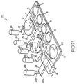
- Fig. 21 is a schematic perspective view of the major components of a coin dispenser 20, which was proposed earlier by the applicant, wherein the basic structure of the conventional coin dispenser 1 depicted in Fig. 18 is adopted, but wherein a feature is added for paying out another different coin having a large diameter, so that it is provided with features for paying out a total of five types of coin.
- the same reference symbols as used in Fig. 18 are used to indicate identical components.
- the payout link 4, payout slider 5 and bottom plate 11, respectively, are elongated toward the left (in the drawing) to accommodate the placement of a change slide 21 having the same structure as the change slides 12, 13, 14 and 15 as described above.
- a hole 22 is also formed in the elongated payout slider 5 to hold another coin of a large diameter.
- a change solenoid 23 is provided at the back end 21b of the change slide 21, similar to the change solenoids 16, 17, 18 and 19 noted earlier, and a change lever 23a configured by the plunger thereof is engaged with the back end 21b of the change slide 21.
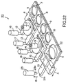
- a coin dispenser 20 when a signal is input from a controller (not shown) to pay out one large- diameter coin held in the hole 22, based on that payout signal, the payout cams 2 and 3 are turned through one revolution, in the direction of the arrows, by the payout drive means (not-shown), causing the payout slider 5 to move reciprocally in the directions of the arrow A, so that the coins held in the holes 7, 8, 9, 10 and 22 of the payout slider 5 are dropped one at a time down through the holes 7, 8, 9, 10 and 22.
- the payout cams 2 and 3 are turned through one revolution, in the direction of the arrows, by the payout drive means (not-shown), causing the payout slider 5 to move reciprocally in the directions of the arrow A, so that the coins held in the holes 7, 8, 9, 10 and 22 of the payout slider 5 are dropped one at a time down through the holes 7, 8, 9, 10 and 22.
- a coin processing apparatus wherein the coin dispenser 1 or 20 described above is loaded, is usually to be loaded in an extremely limited and narrow space inside automatic vending machines or equipment. Therefore, the overall size of the coin processing apparatus is strictly controlled.
- the dimension L in the depth direction from the front to the back in the coin dispenser 1, inclusive of the distance of reciprocal movement of the change slide 14 when paying out coins, is strictly specified.
- an object of the present invention is to provide a coin dispenser wherewith even more types of coins can be paid out without increasing the dimension in the depth direction.
- the coin dispenser of the present invention comprises change slide accommodating means for accommodating the change slide inside the payout link along longitudinal direction thereof; and change slide turning means for turning the change slide in conjunction with movement of the payout link when paying out coins, wherein when paying out the coins, the change slide is turned by the change slide turning means so as to be accommodated inside the change slide accommodating means.
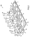
- Fig. 1 is a schematic perspective view of a coin dispenser 30 of one embodiment of the present invention.
- the same reference symbols as used in Figs. 18 and 21 are used to indicate identical components.
- the payout link 4, payout slider 5 and bottom plate 11, respectively, are elongated on the left side (in the drawing) to facilitate the paying out of a different type of coin of large diameter, and a hole 22 is formed in the elongated portion 5a of the payout slider 5 to hold one large- diameter coin.
- the elongated part 4e of the payout link 4 is formed with a change slide storage hole 4f for accommodating the change slide 31 associated with the hole 22 along the longitudinal direction thereof.
- the change slide storage hole 4f configures change slide accommodating means for accommodating the change slide 31 inside the payout link 4 along the longitudinal direction thereof.
- change slide turning means (described below) is formed that turn the change slide 31 in conjunction with the movement of the payout link 4 when paying out coins, respectively.
- the payout cams 2 and 3 are turned through one revolution in the direction of the arrows by the payout drive means (not shown), the payout slider 5 is made to move reciprocally in the directions of the arrow A via the payout link 4, whereby the coins held in the holes 7, 8, 9, 10 and 22 in the payout slider 5 are dropped down one at a time from the holes 7, 8, 9, 10 and 22, and paid out.
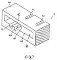
- the change slide turning means 40 comprises a turning shaft 31d that projects from the bottom surface 31c of the change slide 31, of such shape that its side surfaces are partially cut away; a cam shaft 31f on the upper surface 31e of the change slide 31, projecting up from the back end 31b of the change slide 31, as depicted in Fig. 6 which gives a perspective view of the upper surface of the change slide 31; a shaft bearing hole 4h formed in the lower surface 4g of the change slide storage hole 4f, as seen in the enlarged schematic perspective view of the elongated portion 4e of the payout link 4 given in Fig. 7; and an arc shaped cam channel 41 for guiding the cam shaft 31f that projects out from the change slide 31, as depicted in Fig. 1.
- the arc shaped cam channel 41 is formed in the top cover (described below) that covers the upper surface of the payout link 4.
- the shaft 31d is formed by the tip ends of a pair of shaft members 31g and 31h that are split into two forking prongs.
- the diameter of the shaft 31d to contract within that range wherein the gap between the tip ends of the pair of shaft members 31g and 31h flexibly expands and contracts.
- the reference symbol 31i in Fig. 5 indicates a guide panel that projects from the bottom surface 31c of the change slide 31.
- the reference symbol 4i in Fig. 7 designates a guide channel formed adjacent to and to the left of the shaft bearing hole 4h.
- the guide channel 4i accepts the guide panel 31i on the change slide 31 depicted in Fig. 5.
- the reference symbols 4j and 4k in Fig. 7 designate cam shaft accommodating channels for accommodating the cam shaft 31f depicted in Fig. 6.
- the reference symbol 4m in Fig. 7 designates a guide channel for guiding the turning shaft 31d depicted in Fig. 5, oriented toward the shaft bearing hole 4h, so that the turning shaft 31d can go in and out.
- Fig. 8 is a partially cutaway bottom view of the coin dispenser 30 depicted in Fig. 1, as seen from the bottom.
- Fig. 8 details the elongated portions 4e and 5a of the payout link 4 and change slider 5, respectively.
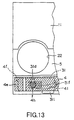
- the cam shaft 31f projecting from the upper surface of the change slide 31 fits inside the arc shaped cam channel 41 formed in the top cover 50 that covers the upper surface of the payout link 4, and the cam shaft 31f is engaged by the change lever 23a of the change solenoid 23 (cf. Fig. 1).
- the payout cams 2 and 3 turn through one revolution in the direction of the arrows, as depicted in Fig. 2, thereby causing, via the payout link 4, the payout slider 5 to move reciprocally in the directions indicated by the arrow A.
- the dimension M in the depth direction from the front to the back of the coin dispenser 30 inclusive of the distance of reciprocal movement of the change slide 31 when paying out coins is far shorter than in the conventional apparatus, because the change slide 31 itself is accommodated inside the payout link 4, thus making it possible to shorten the dimension in the depth direction of the coin dispenser 30 to the maximum extent possible.
- the coin dispenser 30 of the present invention is applied to the paying out and non- paying out of a relatively large- diameter coin held in the hole 22 in the payout slider 5, but the present invention is in no way limited by the embodiment so described, and may be applied to the paying out and non-paying out of coins held in the other holes formed in the payout slider 5, namely the holes 7, 8, 9 and 10, in which case it would be possible to even further shorten the dimension in the depth direction of the coin dispenser overall, as compared to the conventional apparatus.
- the cam shaft 31f is integrally formed with the upper surface 31e of the change slide 31, as shown in Fig. 6.
- the present invention is not limited to this embodiment.
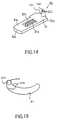
- a metal shaft member 100 is pressed into the upper surface 31e of the change slide 31 in place of the cam shaft 31f, and a roller 101 is rotatably supported by the metal shaft member 100.
- cam shaft 31f is constituted by the metal shaft member 100 and the roller 101, not only the engagement of the cam shaft 31f and the arc shaped cam channel 41 become smooth as shown in Fig. 11, etc., but also durability of the cam shaft 31f improves so that a coin dispenser of long life can be realized.
- the cam channel 41 is formed in a simple arc shape as shown in Fig. 11.
- the starting end 41a of the cam channel 41 may be formed to have a cam channel portion 41b having a smaller radius of curvature compared with the other portions thereof.
- a protrusion 4a' is provided at the fore end of the payout link 4 to prevent the change slide 31 from rotating in the direction of arrow P when the tip 31a of the change slide 31 advances and enters completely the bottom of the hole 22 so as to close off the bottom of the hole 22, and the protrusion 4a' is made abutted to the guide panel 31i.
- a protruding portion 31p is provided at the side of the change slide 31 to cover the gap formed between the payout slide 5 and the protrusion 4a'.
- the gap formed between the payout slide 5 and the protrusion 4a' can be covered so as to prevent a payout coin from being clogged in the gap.
- the payout coin can smoothly drop through the hole 22 and be paid out.
- a change slide that controls the payout and non- payout of coins is made to revolve so that it is accommodated inside the payout link when coins are being paid out, thereby making it possible to set the distance of fore-and-aft movement of the change slide needed during coin payout to be extremely short.
- the dimension in the depth direction of the coin dispenser can be set to be extremely short also, and the coin dispenser made compact.
- coin dispensers can be made compact, furthermore, coin dispensers can be provided that exhibit functions for paying out many kinds of coins, without altering the basic sizes thereof in the depth dimension, even when they are employed in different countries of the world using coins of different types and diameters.
- the coin dispenser of the present invention is a compact apparatus, making it ideal for coin dispensers that pay out many different types of coins, without altering the basic size thereof in the depth dimension, when employed in different countries of the world using coins of different types and diameters.
Landscapes
- Physics & Mathematics (AREA)
- General Physics & Mathematics (AREA)
- Control Of Vending Devices And Auxiliary Devices For Vending Devices (AREA)
- Vending Machines For Individual Products (AREA)
- Purses, Travelling Bags, Baskets, Or Suitcases (AREA)
Applications Claiming Priority (3)
| Application Number | Priority Date | Filing Date | Title |
|---|---|---|---|
| JP32824997 | 1997-11-28 | ||
| JP32824997A JP3734068B2 (ja) | 1997-11-28 | 1997-11-28 | 硬貨払出装置 |
| PCT/JP1998/005313 WO1999028868A1 (fr) | 1997-11-28 | 1998-11-25 | Distributeur de monnaie |
Publications (3)
| Publication Number | Publication Date |
|---|---|
| EP0957455A1 true EP0957455A1 (fr) | 1999-11-17 |
| EP0957455A4 EP0957455A4 (fr) | 2005-03-02 |
| EP0957455B1 EP0957455B1 (fr) | 2006-09-20 |
Family
ID=18208110
Family Applications (1)
| Application Number | Title | Priority Date | Filing Date |
|---|---|---|---|
| EP98955932A Expired - Lifetime EP0957455B1 (fr) | 1997-11-28 | 1998-11-25 | Distributeur de monnaie |
Country Status (9)
| Country | Link |
|---|---|
| US (1) | US6176773B1 (fr) |
| EP (1) | EP0957455B1 (fr) |
| JP (1) | JP3734068B2 (fr) |
| KR (1) | KR100353517B1 (fr) |
| AU (1) | AU715736B2 (fr) |
| CA (1) | CA2280944C (fr) |
| DE (1) | DE69835943T2 (fr) |
| MY (1) | MY122315A (fr) |
| WO (1) | WO1999028868A1 (fr) |
Cited By (4)
| Publication number | Priority date | Publication date | Assignee | Title |
|---|---|---|---|---|
| EP1220164A1 (fr) * | 2000-12-28 | 2002-07-03 | Mars Incorporated | Distributeur de pièces de monnaie |
| EP1164552A3 (fr) * | 2000-06-15 | 2003-02-12 | Sanden Corporation | Dispositif pour distribuer des pièces de monnaie |
| EP1067486A4 (fr) * | 1999-01-27 | 2003-03-26 | Nippon Conlux Co Ltd | Distributeur de pieces de monnaie |
| EP2806408A1 (fr) * | 2013-05-24 | 2014-11-26 | Sanden Corporation | Dispositif de paiement à pièces de monnaie |
Families Citing this family (5)
| Publication number | Priority date | Publication date | Assignee | Title |
|---|---|---|---|---|
| JP4355475B2 (ja) * | 2002-07-26 | 2009-11-04 | 株式会社日本コンラックス | 硬貨処理装置およびその制御方法 |
| JP2007087311A (ja) * | 2005-09-26 | 2007-04-05 | Nippon Conlux Co Ltd | 硬貨処理装置 |
| JP6203603B2 (ja) * | 2013-11-06 | 2017-09-27 | 株式会社日本コンラックス | 硬貨払出装置 |
| JP6320736B2 (ja) | 2013-12-05 | 2018-05-09 | 株式会社日本コンラックス | 硬貨払出装置 |
| JP6656725B2 (ja) * | 2014-12-22 | 2020-03-04 | 株式会社日本コンラックス | 硬貨払出装置 |
Family Cites Families (16)
| Publication number | Priority date | Publication date | Assignee | Title |
|---|---|---|---|---|
| JPS51144698A (en) * | 1975-06-09 | 1976-12-11 | Sanden Corp | Coin carring out device |
| JPS5721092Y2 (fr) * | 1977-11-09 | 1982-05-07 | ||
| JPS54161995A (en) * | 1978-06-13 | 1979-12-22 | Fuji Electric Co Ltd | Change delivery device |
| GB2043317B (en) * | 1979-03-01 | 1983-03-23 | Mars Inc | Coin dispenser |
| JPS5846751B2 (ja) * | 1979-03-09 | 1983-10-18 | 松下電器産業株式会社 | 硬貨払出し装置 |
| JPS56152091A (en) * | 1980-04-25 | 1981-11-25 | Sanyo Jido Hanbaiki Kk | Balance payout device for coin sorter |
| JPS585892A (ja) | 1981-07-03 | 1983-01-13 | 富士電機株式会社 | 釣銭払出装置 |
| US4942605A (en) | 1987-12-08 | 1990-07-17 | Northern Telecom Limited | Security handset |
| JPH0267466A (ja) | 1988-08-31 | 1990-03-07 | Yamaha Motor Co Ltd | 点火制御装置用コードの配線構造 |
| JPH0267475A (ja) | 1988-08-31 | 1990-03-07 | Matsushita Refrig Co Ltd | 密閉型電動圧縮機 |
| JPH0267475U (fr) * | 1988-11-04 | 1990-05-22 | ||
| JPH0615340Y2 (ja) * | 1988-11-10 | 1994-04-20 | サンデン株式会社 | 釣銭払出装置 |
| JP2627372B2 (ja) | 1991-07-24 | 1997-07-02 | 三洋電機株式会社 | 食器洗い乾燥機 |
| JPH0523279U (ja) * | 1991-09-05 | 1993-03-26 | サンデン株式会社 | 硬貨払い出し装置 |
| JPH0711466A (ja) | 1993-06-22 | 1995-01-13 | Tonen Corp | 棒状電極材 |
| JP3299030B2 (ja) * | 1994-04-27 | 2002-07-08 | 株式会社日本コンラックス | 硬貨払出装置 |
-
1997
- 1997-11-28 JP JP32824997A patent/JP3734068B2/ja not_active Expired - Fee Related
-
1998
- 1998-11-25 US US09/355,417 patent/US6176773B1/en not_active Expired - Lifetime
- 1998-11-25 KR KR1019997006420A patent/KR100353517B1/ko not_active Expired - Fee Related
- 1998-11-25 WO PCT/JP1998/005313 patent/WO1999028868A1/fr not_active Ceased
- 1998-11-25 AU AU12601/99A patent/AU715736B2/en not_active Ceased
- 1998-11-25 EP EP98955932A patent/EP0957455B1/fr not_active Expired - Lifetime
- 1998-11-25 DE DE69835943T patent/DE69835943T2/de not_active Expired - Fee Related
- 1998-11-25 CA CA002280944A patent/CA2280944C/fr not_active Expired - Fee Related
- 1998-11-27 MY MYPI98005388A patent/MY122315A/en unknown
Cited By (5)
| Publication number | Priority date | Publication date | Assignee | Title |
|---|---|---|---|---|
| EP1067486A4 (fr) * | 1999-01-27 | 2003-03-26 | Nippon Conlux Co Ltd | Distributeur de pieces de monnaie |
| EP1164552A3 (fr) * | 2000-06-15 | 2003-02-12 | Sanden Corporation | Dispositif pour distribuer des pièces de monnaie |
| EP1220164A1 (fr) * | 2000-12-28 | 2002-07-03 | Mars Incorporated | Distributeur de pièces de monnaie |
| EP2806408A1 (fr) * | 2013-05-24 | 2014-11-26 | Sanden Corporation | Dispositif de paiement à pièces de monnaie |
| JP2014229175A (ja) * | 2013-05-24 | 2014-12-08 | サンデン株式会社 | コイン払出装置 |
Also Published As
| Publication number | Publication date |
|---|---|
| KR100353517B1 (ko) | 2002-09-19 |
| CA2280944C (fr) | 2001-12-11 |
| KR20000070194A (ko) | 2000-11-25 |
| MY122315A (en) | 2006-04-29 |
| JPH11161825A (ja) | 1999-06-18 |
| WO1999028868A1 (fr) | 1999-06-10 |
| DE69835943D1 (de) | 2006-11-02 |
| JP3734068B2 (ja) | 2006-01-11 |
| AU715736B2 (en) | 2000-02-10 |
| DE69835943T2 (de) | 2007-01-18 |
| EP0957455A4 (fr) | 2005-03-02 |
| AU1260199A (en) | 1999-06-16 |
| EP0957455B1 (fr) | 2006-09-20 |
| CA2280944A1 (fr) | 1999-06-10 |
| US6176773B1 (en) | 2001-01-23 |
Similar Documents
| Publication | Publication Date | Title |
|---|---|---|
| EP0957455B1 (fr) | Distributeur de monnaie | |
| KR101967264B1 (ko) | 경화 불출 장치 | |
| JP6320736B2 (ja) | 硬貨払出装置 | |
| US8496100B2 (en) | Coin processing device with temporary coin withholding mechanism | |
| JP4407996B2 (ja) | コイン払出装置 | |
| CN107111905B (zh) | 硬币支出装置 | |
| EP1889230B1 (fr) | Systeme et procede pour la distribution de pieces de monnaie de plusieurs unites de stockage de pieces de monnaie | |
| JP3695908B2 (ja) | 硬貨払出装置 | |
| JP3172349B2 (ja) | 硬貨払い出し装置 | |
| JP3231187B2 (ja) | 硬貨処理装置 | |
| JP3299030B2 (ja) | 硬貨払出装置 | |
| JP2002008087A (ja) | 硬貨払出装置 | |
| HK1237108A1 (en) | Coin payout device | |
| JPH07114660A (ja) | 硬貨処理装置 | |
| JPS6343577Y2 (fr) | ||
| JPH07114659A (ja) | 硬貨処理装置 | |
| JPH0844920A (ja) | コイン払出装置 | |
| JPH07114668A (ja) | 硬貨処理装置 | |
| JP2010026912A (ja) | 硬貨払出装置 | |
| HK1237108B (zh) | 硬币支出装置 | |
| JPH07114661A (ja) | 硬貨処理装置 | |
| JPH06333119A (ja) | 硬貨払出し装置及び自動販売機 | |
| HK1227159B (zh) | 硬币支出装置 | |
| HK1227159A1 (en) | Coin issuing device |
Legal Events
| Date | Code | Title | Description |
|---|---|---|---|
| PUAI | Public reference made under article 153(3) epc to a published international application that has entered the european phase |
Free format text: ORIGINAL CODE: 0009012 |
|
| AK | Designated contracting states |
Kind code of ref document: A1 Designated state(s): DE FR GB IT |
|
| 17P | Request for examination filed |
Effective date: 19991209 |
|
| A4 | Supplementary search report drawn up and despatched |
Effective date: 20050114 |
|
| GRAP | Despatch of communication of intention to grant a patent |
Free format text: ORIGINAL CODE: EPIDOSNIGR1 |
|
| GRAS | Grant fee paid |
Free format text: ORIGINAL CODE: EPIDOSNIGR3 |
|
| GRAA | (expected) grant |
Free format text: ORIGINAL CODE: 0009210 |
|
| AK | Designated contracting states |
Kind code of ref document: B1 Designated state(s): DE FR GB IT |
|
| PG25 | Lapsed in a contracting state [announced via postgrant information from national office to epo] |
Ref country code: IT Free format text: LAPSE BECAUSE OF FAILURE TO SUBMIT A TRANSLATION OF THE DESCRIPTION OR TO PAY THE FEE WITHIN THE PRESCRIBED TIME-LIMIT;WARNING: LAPSES OF ITALIAN PATENTS WITH EFFECTIVE DATE BEFORE 2007 MAY HAVE OCCURRED AT ANY TIME BEFORE 2007. THE CORRECT EFFECTIVE DATE MAY BE DIFFERENT FROM THE ONE RECORDED. Effective date: 20060920 |
|
| REG | Reference to a national code |
Ref country code: GB Ref legal event code: FG4D |
|
| REF | Corresponds to: |
Ref document number: 69835943 Country of ref document: DE Date of ref document: 20061102 Kind code of ref document: P |
|
| ET | Fr: translation filed | ||
| PLBE | No opposition filed within time limit |
Free format text: ORIGINAL CODE: 0009261 |
|
| STAA | Information on the status of an ep patent application or granted ep patent |
Free format text: STATUS: NO OPPOSITION FILED WITHIN TIME LIMIT |
|
| 26N | No opposition filed |
Effective date: 20070621 |
|
| REG | Reference to a national code |
Ref country code: GB Ref legal event code: 732E |
|
| REG | Reference to a national code |
Ref country code: FR Ref legal event code: TP |
|
| PGFP | Annual fee paid to national office [announced via postgrant information from national office to epo] |
Ref country code: DE Payment date: 20081120 Year of fee payment: 11 |
|
| PGFP | Annual fee paid to national office [announced via postgrant information from national office to epo] |
Ref country code: IT Payment date: 20081127 Year of fee payment: 11 |
|
| PGFP | Annual fee paid to national office [announced via postgrant information from national office to epo] |
Ref country code: FR Payment date: 20081112 Year of fee payment: 11 |
|
| REG | Reference to a national code |
Ref country code: FR Ref legal event code: TP Ref country code: FR Ref legal event code: CD Ref country code: FR Ref legal event code: CA |
|
| REG | Reference to a national code |
Ref country code: FR Ref legal event code: RERR Free format text: CORRECTION DE BOPI 08/12 - TRANSMISSION TOTALE DE PROPRIETE. IL Y A LIEU DE SUPPRIMER : L INSCRIPTION N163225 DU 12/02/08 CONCERNANT LE BREVET EUROPEEN N0957455 |
|
| PGFP | Annual fee paid to national office [announced via postgrant information from national office to epo] |
Ref country code: GB Payment date: 20091125 Year of fee payment: 12 |
|
| REG | Reference to a national code |
Ref country code: FR Ref legal event code: ST Effective date: 20100730 |
|
| PG25 | Lapsed in a contracting state [announced via postgrant information from national office to epo] |
Ref country code: FR Free format text: LAPSE BECAUSE OF NON-PAYMENT OF DUE FEES Effective date: 20091130 |
|
| PG25 | Lapsed in a contracting state [announced via postgrant information from national office to epo] |
Ref country code: DE Free format text: LAPSE BECAUSE OF NON-PAYMENT OF DUE FEES Effective date: 20100601 |
|
| PG25 | Lapsed in a contracting state [announced via postgrant information from national office to epo] |
Ref country code: IT Free format text: LAPSE BECAUSE OF NON-PAYMENT OF DUE FEES Effective date: 20091125 |
|
| GBPC | Gb: european patent ceased through non-payment of renewal fee |
Effective date: 20101125 |
|
| PG25 | Lapsed in a contracting state [announced via postgrant information from national office to epo] |
Ref country code: GB Free format text: LAPSE BECAUSE OF NON-PAYMENT OF DUE FEES Effective date: 20101125 |