EP0957463A2 - Gelenkiges Element zur Befestigung eines Eindringsensors an einer Wand und/oder Decke - Google Patents
Gelenkiges Element zur Befestigung eines Eindringsensors an einer Wand und/oder Decke Download PDFInfo
- Publication number
- EP0957463A2 EP0957463A2 EP99109436A EP99109436A EP0957463A2 EP 0957463 A2 EP0957463 A2 EP 0957463A2 EP 99109436 A EP99109436 A EP 99109436A EP 99109436 A EP99109436 A EP 99109436A EP 0957463 A2 EP0957463 A2 EP 0957463A2
- Authority
- EP
- European Patent Office
- Prior art keywords
- pin
- detection device
- apt
- ceiling
- washer
- Prior art date
- Legal status (The legal status is an assumption and is not a legal conclusion. Google has not performed a legal analysis and makes no representation as to the accuracy of the status listed.)
- Granted
Links
Images


Classifications
-
- F—MECHANICAL ENGINEERING; LIGHTING; HEATING; WEAPONS; BLASTING
- F16—ENGINEERING ELEMENTS AND UNITS; GENERAL MEASURES FOR PRODUCING AND MAINTAINING EFFECTIVE FUNCTIONING OF MACHINES OR INSTALLATIONS; THERMAL INSULATION IN GENERAL
- F16M—FRAMES, CASINGS OR BEDS OF ENGINES, MACHINES OR APPARATUS, NOT SPECIFIC TO ENGINES, MACHINES OR APPARATUS PROVIDED FOR ELSEWHERE; STANDS; SUPPORTS
- F16M11/00—Stands or trestles as supports for apparatus or articles placed thereon ; Stands for scientific apparatus such as gravitational force meters
- F16M11/02—Heads
- F16M11/04—Means for attachment of apparatus; Means allowing adjustment of the apparatus relatively to the stand
- F16M11/06—Means for attachment of apparatus; Means allowing adjustment of the apparatus relatively to the stand allowing pivoting
- F16M11/10—Means for attachment of apparatus; Means allowing adjustment of the apparatus relatively to the stand allowing pivoting around a horizontal axis
-
- F—MECHANICAL ENGINEERING; LIGHTING; HEATING; WEAPONS; BLASTING
- F16—ENGINEERING ELEMENTS AND UNITS; GENERAL MEASURES FOR PRODUCING AND MAINTAINING EFFECTIVE FUNCTIONING OF MACHINES OR INSTALLATIONS; THERMAL INSULATION IN GENERAL
- F16M—FRAMES, CASINGS OR BEDS OF ENGINES, MACHINES OR APPARATUS, NOT SPECIFIC TO ENGINES, MACHINES OR APPARATUS PROVIDED FOR ELSEWHERE; STANDS; SUPPORTS
- F16M13/00—Other supports for positioning apparatus or articles; Means for steadying hand-held apparatus or articles
- F16M13/02—Other supports for positioning apparatus or articles; Means for steadying hand-held apparatus or articles for supporting on, or attaching to, an object, e.g. tree, gate, window-frame, cycle
- F16M13/027—Ceiling supports
-
- G—PHYSICS
- G08—SIGNALLING
- G08B—SIGNALLING SYSTEMS, e.g. PERSONAL CALLING SYSTEMS; ORDER TELEGRAPHS; ALARM SYSTEMS
- G08B13/00—Burglar, theft or intruder alarms
- G08B13/18—Actuation by interference with heat, light, or radiation of shorter wavelength; Actuation by intruding sources of heat, light, or radiation of shorter wavelength
- G08B13/189—Actuation by interference with heat, light, or radiation of shorter wavelength; Actuation by intruding sources of heat, light, or radiation of shorter wavelength using passive radiation detection systems
- G08B13/19—Actuation by interference with heat, light, or radiation of shorter wavelength; Actuation by intruding sources of heat, light, or radiation of shorter wavelength using passive radiation detection systems using infrared-radiation detection systems
Definitions
- the present invention relates to an articulated element for fixing to a wall and/or a ceiling a detection device, in particular an anti-intrusion device, and to a detection device comprising said articulated element.
- anti-theft or anti-intrusion devices may be located either on a wall or on the ceiling, depending upon the environment to be protected; in order to provide both types of installation, anti-intrusion devices may be equipped with an articulated coupling.
- Said articulated coupling generally provides for a support, having a base on one end for its fixing to the wall or the ceiling, whereas the other end has a substantially spherical head; such a spherical head is apt to be inserted in a semispherical cavity provided in the body of the anti-intrusion device.
- Coupling between the two components i.e. between the spherical head of the support and the body of the anti-intrusion device, is usually ensured by a screw, which is screwed in the spherical head of the support from inside the body of the anti-intrusion device.
- said semispherical cavity, and consequently the body of the anti-intrusion device can be rotated to all directions on the spherical head of the support, so as to orient the device according to the specific requirements of the environment to be protected; once a correct work position is reached, the body of the device is secured on the support, by tightening the fastening screw.
- tampering may take place by forcing orientation of the active section of the anti-intrusion device towards an area requiring no coverage, such as directing it towards the wall itself or the ceiling, so that it is no longer possible for the anti-intrusion device to perform its detection functions correctly. Since the body of the anti-intrusion can be rotated to all directions, a displacement due to a tampering attempt may take place either towards the wall or the ceiling, independently from the point where the device is correctly fixed to.
- Orientation of the anti-intrusion device can be tampered by forcing the movement of the body of the device, even if it is fixed by a screw to the spherical head of its relevant support; it should be noticed, in fact, that the fastening between the two components cannot be obtained too rigidly (i.e. the above screw should not be tightened too much), since this may entail a risk of deformation or cracks to the components themselves, which are made of plastic material, either totally or partially.
- tampering may also be caused by a torsional or angular movement of the anti-intrusion device, so as to change the position of its detection field.
- the electric connection between the sensor of the anti-intrusion device and the elaboration system of the relevant signal, being emitted in the event of a likely intrusion in the environment to be protected, is obtained through an external cable, a portion of which is directly accessible; in particular, in fact, a portion of such a cable extends in sight between a special outlet in the wall and a hole provided on the body of the anti-intrusion device.
- Such a configuration allows an easy tampering to the cable, such as short-circuiting it, which would make the anti-intrusion device inoperative.
- the present invention has the purpose of solving the above drawbacks and provide an articulated element for the fixing to a wall and/or a ceiling of a detection device, in particular an anti-intrusion device, and a detection device comprising such an articulated element, having a higher safety against tampering, which is easy to install and use, having low manufacturing costs.
- a first aim of the present invention is to provide an articulated element for the fixing to a wall and/or a ceiling of a detection device, in particular an anti-intrusion device, which is equipped with suitable means for preventing an undesired change of the work position assigned to the detection device at its installation stage.
- a second aim of the present invention is to provide an articulated element for the fixing to a wall and/or a ceiling of a detection device, in particular an anti-intrusion device, where tampering risks to the electric connection cable between the anti-intrusion device and a relevant elaboration systems are removed.
- an articulated element for the fixing to a wall and/or a ceiling of a detection device, in particular an anti-intrusion device, and a detection device comprising said articulated element incorporating the features of the annexed claims, which form an integral part of the present description.
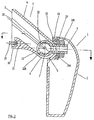
- Number 2 indicates a support for an articulated element which is used for fixing purposes of the anti-intrusion device 1 to a wall and/or a ceiling.
- the support 2 has a base 3 for its resting and fastening either to a wall (Fig. 2) or to a ceiling (Fig. 3), wherefrom a hollow element 4 departs with a certain inclination, which end with an end 5 whose external part is semispherical shaped.
- This end 5 has a slit 6, which is substantially rectangular and is arranged with its main axis in a substantially vertical position.
- Number 8 indicates two holes on the hollow element 4, obtained along the axis of the semicircular seats 7and of the semispherical end 5.
- Number 9 indicates a pin having an section being substantially extended-ring shaped, i.e. with two semicircular ends connected by two substantially parallel sides; the pin 9 is hollow inside so as to allow one or more connection wires of the anti-intrusion device 1 to go through to the relevant control system.
- a first end 10 of said pin 9 has a substantially circular or disk shape; the diameter of said end 10 is substantially corresponding to the inside diameter of the semispherical end 5, whereas its thickness is equal to the smaller dimension of the section of the pin 9.
- the pin 9 On its second end 11, the pin 9 has a thread suitable for screwing a nut 11A.
- the first disk end 10 On each one of its two flat surfaces, the first disk end 10 has a cylindrical protrusion 12, whose diameter is twice the radius of the semicircular seats 7 it will be coupled with; in other words, both cylindrical protrusions 12 are apt to be exactly mated in the seats 7.
- a knurling is defined, being not visible in the figures, along one portion 12A of the circumference of each one of said cylindrical protrusions 12, and in particular the portion corresponding to the contact area with the relevant semicircular seat 7.
- a pin 13 is present, whose diameter can be inserted in the holes 8 of the hollow element 4.
- the pin 9 is inserted through an opening being present in the base 3, within the hollow element 4, until its threaded end 11 comes out of the slit 6 and pins 13 are snap inserted in the holes 8; moreover, under this condition, the cylindrical protrusions 12 rest in the seats 7.
- two side guides 23 may be provided within the hollow body 4, whose purpose is to guide the insertion of the pin 9 until pins 13 are snap inserted in the holes 8.
- the pin 9 results in being fastened to the hollow element 4, but with the possibility of its vertical motion, i.e. downwards and upwards in a field delimited by the slit 6, the rotary axis of the pin 9 consisting of pins 13.
- a semispherical cavity 15 is defined on the external body of the anti-intrusion device 1, in particular in its rear portion, wherein the semispherical end 5 is inserted during the device assembly stage.
- the semispherical cavity 15 has a central horizontal slit 16 having a substantially rectangular configuration, which is apt to receive the threaded end 11 of the pin 9; in particular, the width of the slit 16 is substantially equal to the greater dimension of the end 11 of the pin 9.
- the semispherical cavity 15 is defined in a portion 15A of the device 1 having a substantially semi-cylindrical section, as it can be easily seen from a comparison between Figs. 2 and 4; on the internal surface of such a portion 15A two notches 17 are present (Fig. 4), each one being adjacent to a greater side of the slit 16.
- Number 18 indicates a washer laying between the nut 11A and the body of the anti-intrusion device 1; the outside surface of the washer 18 in contact with the nut 11A is flat, whereas the opposite surface is semicircular and has a notch being complementary with respect to the notches 17; the central hole of the washer 18 has substantially the same dimensions and shape as the end 11 of the pin 9.
- the body of the device 1 is fastened to the support 2 as further described; to this purpose, it should be remembered, anyway, that during such an assembly step the front part of the body of device 1 is open, i.e. a cover indicated with C in the figures is preliminarily removed from it.
- the cavity 15 of the body of the device 1 is placed on the end 5 of the support, so that the threaded end 11 of the pin 9 is inserted in the slit 16.
- the body of the device 1 is then oriented to work position deemed to be correct, the slit 6 allowing adjustment in its vertical direction and the slit 16 allowing adjustment in its horizontal direction.
- the nut 11A is tightened; this tightening causes the notch of the washer 18 to firmly engage with the notches 17 of the portion 15A; such an engagement is such to prevent displacement of the device body 1 in a horizontal direction, even when trying to displace it during a likely subsequent tampering attempt.
- the tightening of the screw 11A on the washer 18 causes the knurling being present along a portion 12A of the circumference of the cylindrical protrusions 12 of the pin 9, to interfere with the semicircular seats 7; such an interference is such to prevent a rotary motion in a vertical direction of the body of the device 1, so that a tampering attempt to its orientation in that direction is hindered.
- a likely torsion stress on the anti-intrusion device 1, i.e. an angular movement being imparted to it, for a possible tampering attempt is hindered in that the central hole of the washer 18 has substantially the same dimensions and shape as the end 11 of the pin 9 and in that the shape of the washer itself mates with the surface of the portion 15A.
- both its upper and lower ends may be provided with feet 19, which are apt to mate with respective steps delimited on the ends of the portion 15A, thus developing a further resistance point to torsion stress.
- the support 2 of the articulated element is positioned as represented in Fig. 3, i.e. with its base 3 fastened to the ceiling and its semispherical end 5 directed to the area under control.
- the length extension of the slit 6 and of the hollow element 4 are selected so that a complete downwards displacement of the device body 1 is hindered by the striking of the body itself against a wall, thus warranting in any case a survey coverage of a significant area of the environment under control.
- a tampering attempt of the device cannot occur operating on the nut 11A, since this would presume acting on the front portion of the device 1, which is submitted to the intrusion detection; in any case, a special sensor (such as a micro-switch, can be provided inside the device body, just for detecting a likely removal of the cover C).
- a special sensor such as a micro-switch
- an articulated element for the fixing to a wall and/or a ceiling of a detection device comprising means for the fixing to a wall and/or a ceiling, orientation means, means for the fixing of said detection device in the working position, where mechanical means are provided, which are apt to prevent tampering of the detection device by trying to change said working position.
- Said mechanical means are particularly apt to hinder a change in the working position of said device in its vertical direction and/or its horizontal direction and/or its angular direction.
- a sensor may be inserted, which is apt to detect its detachment from the wall and/or ceiling following a tampering attempt.
- number 20 indicates such a sensor comprising a micro-switch 21 of the normally open type, and a spring 22.
- the spring 22 When the device is fastened to the wall and/or ceiling, the spring 22 is under load and therefore operate on the switch 21, bringing it to its closed position.
- the spring no longer under pressure, releases the switch, which can go over to its opening position, so causing the intervention of the control system, which activates an alarm signal.
- a further possible variant embodiment consists in providing indentations, being the notches as previously indicated with 17, both on the portion 12A of the circumference of the cylindrical protrusions 12 and on the surface of the semicircular seats 7, in order avoid any further the possibility of rotary motion in the vertical direction of the body of the device 1.
- Another variant embodiment could consist in using not purely mechanical means, such as micro-switches, magnetic and/or optical sensors, to avoid tampering attempts to said detection device 1, i.e. producing an alarm signal should a work position change to the device itself be attempted.
Landscapes
- Engineering & Computer Science (AREA)
- General Engineering & Computer Science (AREA)
- Mechanical Engineering (AREA)
- Physics & Mathematics (AREA)
- General Physics & Mathematics (AREA)
- Burglar Alarm Systems (AREA)
- Geophysics And Detection Of Objects (AREA)
- Spectrometry And Color Measurement (AREA)
- Measuring Oxygen Concentration In Cells (AREA)
Applications Claiming Priority (2)
| Application Number | Priority Date | Filing Date | Title |
|---|---|---|---|
| IT98TO000392A ITTO980392A1 (it) | 1998-05-11 | 1998-05-11 | Elemento snodabile per il fissaggio a parete e/o a soffitto di un dispositivo di rilevazione, in particolare un dispositivo anti-intru- |
| ITTO980392 | 1998-05-11 |
Publications (3)
| Publication Number | Publication Date |
|---|---|
| EP0957463A2 true EP0957463A2 (de) | 1999-11-17 |
| EP0957463A3 EP0957463A3 (de) | 2001-03-21 |
| EP0957463B1 EP0957463B1 (de) | 2004-09-08 |
Family
ID=11416742
Family Applications (1)
| Application Number | Title | Priority Date | Filing Date |
|---|---|---|---|
| EP99109436A Expired - Lifetime EP0957463B1 (de) | 1998-05-11 | 1999-05-11 | Gelenkiges Element zur Befestigung eines Eindringsensors an einer Wand und/oder Decke |
Country Status (4)
| Country | Link |
|---|---|
| EP (1) | EP0957463B1 (de) |
| AT (1) | ATE275748T1 (de) |
| DE (1) | DE69919933D1 (de) |
| IT (1) | ITTO980392A1 (de) |
Cited By (1)
| Publication number | Priority date | Publication date | Assignee | Title |
|---|---|---|---|---|
| FR2814217A1 (fr) * | 2000-09-18 | 2002-03-22 | Philippe Floris Jean Lepers | Rotule creuse de liaison |
Family Cites Families (6)
| Publication number | Priority date | Publication date | Assignee | Title |
|---|---|---|---|---|
| DE3016930A1 (de) * | 1980-05-02 | 1981-11-05 | Robert Bosch Gmbh, 7000 Stuttgart | Montagebox, insbesondere zur aufnahme und positionsgerechten anbringung des detektors einer gefahrenmeldeanlage zum diebstahlschutz, feuerschutz, zur eibruchssicherung o.dgl. |
| GB2162352A (en) * | 1984-07-13 | 1986-01-29 | Picking Robert Michael | Space protection device |
| FR2572576B1 (fr) * | 1984-10-29 | 1989-11-24 | Amar Roger | Boitier orientable a montage mural ou plafonnier |
| GB2285913B (en) * | 1994-01-26 | 1997-09-03 | Texecom Limited | A bracket and a housing assembly |
| FR2749618B1 (fr) * | 1996-06-07 | 1998-08-07 | Atral | Dispositif de montage pour le positionnement et le maintien de deux pieces l'une par rapport a l'autre |
| WO1998008020A1 (en) * | 1996-08-21 | 1998-02-26 | Texecom Limited | A bracket assembly |
-
1998
- 1998-05-11 IT IT98TO000392A patent/ITTO980392A1/it unknown
-
1999
- 1999-05-11 EP EP99109436A patent/EP0957463B1/de not_active Expired - Lifetime
- 1999-05-11 DE DE69919933T patent/DE69919933D1/de not_active Expired - Lifetime
- 1999-05-11 AT AT99109436T patent/ATE275748T1/de not_active IP Right Cessation
Cited By (1)
| Publication number | Priority date | Publication date | Assignee | Title |
|---|---|---|---|---|
| FR2814217A1 (fr) * | 2000-09-18 | 2002-03-22 | Philippe Floris Jean Lepers | Rotule creuse de liaison |
Also Published As
| Publication number | Publication date |
|---|---|
| EP0957463B1 (de) | 2004-09-08 |
| DE69919933D1 (de) | 2004-10-14 |
| ATE275748T1 (de) | 2004-09-15 |
| EP0957463A3 (de) | 2001-03-21 |
| ITTO980392A1 (it) | 1999-11-11 |
Similar Documents
| Publication | Publication Date | Title |
|---|---|---|
| EP1569182B1 (de) | Detektion von unbefugten Manipulation für ein Sicherheitssystem | |
| US4683356A (en) | Taut wire fence system and sensor therefor | |
| US5692721A (en) | Tamper-proof bracket and housing assembly | |
| EP3765786B1 (de) | Motorisierter einbaustrahler | |
| US5782438A (en) | Versatile mounting and adjustment system for passive infrared detector | |
| US4713506A (en) | Electrical contact making arrangement for monitoring the condition of a screw in an installed position | |
| EP0957463B1 (de) | Gelenkiges Element zur Befestigung eines Eindringsensors an einer Wand und/oder Decke | |
| US20130194095A1 (en) | Security Alarm System Device and Component for Securing Outdoor Appliances | |
| CA3017009A1 (en) | Restricted swivel knuckle design to a void twisting of wires | |
| US6737972B1 (en) | Vibration sensor | |
| JPS6341100A (ja) | フレキシブルな電気ケ−ブルの保護装置 | |
| US4027548A (en) | Remote control mirror | |
| KR100815769B1 (ko) | 카메라 고정장치 | |
| JP2012514806A (ja) | 弾持球を備えるフェンスの乗越え検知棒 | |
| KR102053891B1 (ko) | 무인 지상 센서용 안테나 | |
| US4771273A (en) | Anti-tamper bracket | |
| JP2602143B2 (ja) | 通電式ワイヤ張力検出型警戒センサ | |
| WO2007114628A1 (en) | Fiber optic mesh for fence and fiber optic cable fixture and base fixture thereof | |
| KR100785681B1 (ko) | 방재 방범 기기 | |
| CA1085944A (en) | Shock and vibration sensitive switch | |
| EP0614041B1 (de) | Befestigungsvorrichtung für Einbauleuchten | |
| CN219712898U (zh) | 探测器 | |
| US6094136A (en) | Burglar alarm protection system | |
| US5053589A (en) | Vibration sensing device | |
| KR200475286Y1 (ko) | 템퍼 스위치 |
Legal Events
| Date | Code | Title | Description |
|---|---|---|---|
| PUAI | Public reference made under article 153(3) epc to a published international application that has entered the european phase |
Free format text: ORIGINAL CODE: 0009012 |
|
| AK | Designated contracting states |
Kind code of ref document: A2 Designated state(s): AT BE CH DE ES FR GB GR LI NL PT |
|
| AX | Request for extension of the european patent |
Free format text: AL;LT;LV;RO;SI |
|
| PUAL | Search report despatched |
Free format text: ORIGINAL CODE: 0009013 |
|
| AK | Designated contracting states |
Kind code of ref document: A3 Designated state(s): AT BE CH CY DE DK ES FI FR GB GR IE IT LI LU MC NL PT SE |
|
| AX | Request for extension of the european patent |
Free format text: AL;LT;LV;RO;SI |
|
| RIC1 | Information provided on ipc code assigned before grant |
Free format text: 7G 08B 13/19 A, 7F 16M 11/12 B |
|
| 17P | Request for examination filed |
Effective date: 20010925 |
|
| AKX | Designation fees paid |
Free format text: AT BE CH DE ES FR GB GR LI NL PT |
|
| 17Q | First examination report despatched |
Effective date: 20030227 |
|
| GRAP | Despatch of communication of intention to grant a patent |
Free format text: ORIGINAL CODE: EPIDOSNIGR1 |
|
| GRAS | Grant fee paid |
Free format text: ORIGINAL CODE: EPIDOSNIGR3 |
|
| GRAA | (expected) grant |
Free format text: ORIGINAL CODE: 0009210 |
|
| AK | Designated contracting states |
Kind code of ref document: B1 Designated state(s): AT BE CH DE ES FR GB GR LI NL PT |
|
| PG25 | Lapsed in a contracting state [announced via postgrant information from national office to epo] |
Ref country code: NL Free format text: LAPSE BECAUSE OF FAILURE TO SUBMIT A TRANSLATION OF THE DESCRIPTION OR TO PAY THE FEE WITHIN THE PRESCRIBED TIME-LIMIT Effective date: 20040908 Ref country code: LI Free format text: LAPSE BECAUSE OF FAILURE TO SUBMIT A TRANSLATION OF THE DESCRIPTION OR TO PAY THE FEE WITHIN THE PRESCRIBED TIME-LIMIT Effective date: 20040908 Ref country code: CH Free format text: LAPSE BECAUSE OF FAILURE TO SUBMIT A TRANSLATION OF THE DESCRIPTION OR TO PAY THE FEE WITHIN THE PRESCRIBED TIME-LIMIT Effective date: 20040908 Ref country code: BE Free format text: LAPSE BECAUSE OF FAILURE TO SUBMIT A TRANSLATION OF THE DESCRIPTION OR TO PAY THE FEE WITHIN THE PRESCRIBED TIME-LIMIT Effective date: 20040908 Ref country code: AT Free format text: LAPSE BECAUSE OF FAILURE TO SUBMIT A TRANSLATION OF THE DESCRIPTION OR TO PAY THE FEE WITHIN THE PRESCRIBED TIME-LIMIT Effective date: 20040908 |
|
| REG | Reference to a national code |
Ref country code: GB Ref legal event code: FG4D |
|
| REG | Reference to a national code |
Ref country code: CH Ref legal event code: EP |
|
| REF | Corresponds to: |
Ref document number: 69919933 Country of ref document: DE Date of ref document: 20041014 Kind code of ref document: P |
|
| PG25 | Lapsed in a contracting state [announced via postgrant information from national office to epo] |
Ref country code: GR Free format text: LAPSE BECAUSE OF FAILURE TO SUBMIT A TRANSLATION OF THE DESCRIPTION OR TO PAY THE FEE WITHIN THE PRESCRIBED TIME-LIMIT Effective date: 20041208 |
|
| PG25 | Lapsed in a contracting state [announced via postgrant information from national office to epo] |
Ref country code: DE Free format text: LAPSE BECAUSE OF FAILURE TO SUBMIT A TRANSLATION OF THE DESCRIPTION OR TO PAY THE FEE WITHIN THE PRESCRIBED TIME-LIMIT Effective date: 20041209 |
|
| PG25 | Lapsed in a contracting state [announced via postgrant information from national office to epo] |
Ref country code: ES Free format text: LAPSE BECAUSE OF FAILURE TO SUBMIT A TRANSLATION OF THE DESCRIPTION OR TO PAY THE FEE WITHIN THE PRESCRIBED TIME-LIMIT Effective date: 20041219 |
|
| NLV1 | Nl: lapsed or annulled due to failure to fulfill the requirements of art. 29p and 29m of the patents act | ||
| REG | Reference to a national code |
Ref country code: CH Ref legal event code: PL |
|
| PLBE | No opposition filed within time limit |
Free format text: ORIGINAL CODE: 0009261 |
|
| STAA | Information on the status of an ep patent application or granted ep patent |
Free format text: STATUS: NO OPPOSITION FILED WITHIN TIME LIMIT |
|
| ET | Fr: translation filed | ||
| 26N | No opposition filed |
Effective date: 20050609 |
|
| PG25 | Lapsed in a contracting state [announced via postgrant information from national office to epo] |
Ref country code: PT Free format text: LAPSE BECAUSE OF NON-PAYMENT OF DUE FEES Effective date: 20050208 |
|
| REG | Reference to a national code |
Ref country code: GB Ref legal event code: 732E Free format text: REGISTERED BETWEEN 20120705 AND 20120711 |
|
| PGFP | Annual fee paid to national office [announced via postgrant information from national office to epo] |
Ref country code: GB Payment date: 20120518 Year of fee payment: 14 Ref country code: FR Payment date: 20120615 Year of fee payment: 14 |
|
| REG | Reference to a national code |
Ref country code: FR Ref legal event code: TP Owner name: URMET S.P.A., IT Effective date: 20130703 |
|
| GBPC | Gb: european patent ceased through non-payment of renewal fee |
Effective date: 20130511 |
|
| REG | Reference to a national code |
Ref country code: FR Ref legal event code: ST Effective date: 20140131 |
|
| PG25 | Lapsed in a contracting state [announced via postgrant information from national office to epo] |
Ref country code: GB Free format text: LAPSE BECAUSE OF NON-PAYMENT OF DUE FEES Effective date: 20130511 |
|
| PG25 | Lapsed in a contracting state [announced via postgrant information from national office to epo] |
Ref country code: FR Free format text: LAPSE BECAUSE OF NON-PAYMENT OF DUE FEES Effective date: 20130531 |