EP0957497A2 - Schalter zur Steuerung eines Gleichstromelektrowerkzeuges mit veränderlicher Geschwindigkeit - Google Patents
Schalter zur Steuerung eines Gleichstromelektrowerkzeuges mit veränderlicher Geschwindigkeit Download PDFInfo
- Publication number
- EP0957497A2 EP0957497A2 EP99109186A EP99109186A EP0957497A2 EP 0957497 A2 EP0957497 A2 EP 0957497A2 EP 99109186 A EP99109186 A EP 99109186A EP 99109186 A EP99109186 A EP 99109186A EP 0957497 A2 EP0957497 A2 EP 0957497A2
- Authority
- EP
- European Patent Office
- Prior art keywords
- contact
- battery
- speed control
- bypass
- variable speed
- Prior art date
- Legal status (The legal status is an assumption and is not a legal conclusion. Google has not performed a legal analysis and makes no representation as to the accuracy of the status listed.)
- Granted
Links
- 239000007787 solid Substances 0.000 claims abstract description 8
- 239000012777 electrically insulating material Substances 0.000 claims description 7
- 230000007659 motor function Effects 0.000 claims description 5
- 230000009471 action Effects 0.000 claims description 2
- 230000006870 function Effects 0.000 description 4
- 230000000994 depressogenic effect Effects 0.000 description 2
- 239000000463 material Substances 0.000 description 2
- 230000003466 anti-cipated effect Effects 0.000 description 1
- 239000000872 buffer Substances 0.000 description 1
- 239000011248 coating agent Substances 0.000 description 1
- 238000000576 coating method Methods 0.000 description 1
- 230000006835 compression Effects 0.000 description 1
- 238000007906 compression Methods 0.000 description 1
- 239000004020 conductor Substances 0.000 description 1
- 230000000881 depressing effect Effects 0.000 description 1
- 238000010586 diagram Methods 0.000 description 1
- 230000005669 field effect Effects 0.000 description 1
- 239000011810 insulating material Substances 0.000 description 1
- 239000002184 metal Substances 0.000 description 1
- 229910044991 metal oxide Inorganic materials 0.000 description 1
- 150000004706 metal oxides Chemical class 0.000 description 1
- 238000000034 method Methods 0.000 description 1
- 230000008569 process Effects 0.000 description 1
- 230000007704 transition Effects 0.000 description 1
- 230000032258 transport Effects 0.000 description 1
Images


Classifications
-
- H—ELECTRICITY
- H01—ELECTRIC ELEMENTS
- H01H—ELECTRIC SWITCHES; RELAYS; SELECTORS; EMERGENCY PROTECTIVE DEVICES
- H01H9/00—Details of switching devices, not covered by groups H01H1/00 - H01H7/00
- H01H9/02—Bases, casings, or covers
- H01H9/06—Casing of switch constituted by a handle serving a purpose other than the actuation of the switch, e.g. by the handle of a vacuum cleaner
- H01H9/061—Casing of switch constituted by a handle serving a purpose other than the actuation of the switch, e.g. by the handle of a vacuum cleaner enclosing a continuously variable impedance
-
- H—ELECTRICITY
- H01—ELECTRIC ELEMENTS
- H01H—ELECTRIC SWITCHES; RELAYS; SELECTORS; EMERGENCY PROTECTIVE DEVICES
- H01H9/00—Details of switching devices, not covered by groups H01H1/00 - H01H7/00
- H01H9/02—Bases, casings, or covers
- H01H9/06—Casing of switch constituted by a handle serving a purpose other than the actuation of the switch, e.g. by the handle of a vacuum cleaner
- H01H2009/065—Battery operated hand tools in which the battery and the switch are directly connected
-
- H—ELECTRICITY
- H01—ELECTRIC ELEMENTS
- H01H—ELECTRIC SWITCHES; RELAYS; SELECTORS; EMERGENCY PROTECTIVE DEVICES
- H01H2300/00—Orthogonal indexing scheme relating to electric switches, relays, selectors or emergency protective devices covered by H01H
- H01H2300/002—Application electric motor braking, e.g. pole reversal of rotor, shorting motor coils, also for field discharge
-
- H—ELECTRICITY
- H01—ELECTRIC ELEMENTS
- H01H—ELECTRIC SWITCHES; RELAYS; SELECTORS; EMERGENCY PROTECTIVE DEVICES
- H01H9/00—Details of switching devices, not covered by groups H01H1/00 - H01H7/00
- H01H9/52—Cooling of switch parts
-
- Y—GENERAL TAGGING OF NEW TECHNOLOGICAL DEVELOPMENTS; GENERAL TAGGING OF CROSS-SECTIONAL TECHNOLOGIES SPANNING OVER SEVERAL SECTIONS OF THE IPC; TECHNICAL SUBJECTS COVERED BY FORMER USPC CROSS-REFERENCE ART COLLECTIONS [XRACs] AND DIGESTS
- Y10—TECHNICAL SUBJECTS COVERED BY FORMER USPC
- Y10S—TECHNICAL SUBJECTS COVERED BY FORMER USPC CROSS-REFERENCE ART COLLECTIONS [XRACs] AND DIGESTS
- Y10S388/00—Electricity: motor control systems
- Y10S388/935—Specific application:
- Y10S388/937—Hand tool
Definitions
- the present invention relates to variable speed controls for direct current electric motors; and more particularly to such controls for operating hand-held, battery powered tools which are driven by an electric motor.
- Hand-held power tools such as electric drills and dry-wall screwdrivers, utilize a DC electric motor to rotate a bit which either drills a hole or turns a screw.
- These power tools often have a pistol-like grip with a trigger which is manually operated by the user of the tool with the speed of the motor being controlled by the degree to which the user presses the trigger.
- This allows the speed of the drill or screwdriver bit to be varied depending upon the particular application for the tool.
- the speed of a drill bit can be controlled to correspond to the hardness of the material being drilled; e.g. the harder the material, the slower the drill bit should rotate.
- the trigger which is spring biased into an off position, is mechanically connected to a switch which closes upon the user depressing the trigger from that off position.
- the trigger also is mechanically connected to a wiper of a potentiometer in the speed control circuit and the resistance of the potentiometer changes with trigger movement.
- One type of control circuit responds to changes in the potentiometer resistance by pulse width modulating the electric current applied to the motor. That is, the electric current is applied in the form of pulses having duty cycles that vary to control the motor speed. The greater the duty cycle, the longer the current pulse, and the faster the motor operates.
- the trigger operates several contacts of the speed control switch and it is desirable to have the switch be compact and cost effective while providing smooth control of the tool's speed.
- a general object of the present invention is to provide a variable speed control circuit for a hand-held power tool driven by a direct current motor.
- Another object is to provide a compact multiple function switch for the variable speed control circuit.
- a further object of the present invention is to provide a switch having a single moveable contact which sequentially engages a plurality of stationary contacts for different modes of motor operation.
- a control circuit includes a function switch having a series of stationary contacts.
- a first battery contact is provided to connect to a first terminal of a battery.
- a speed control contact is adjacent to the first battery contact and is intended to be connected to a first terminal of the motor by a solid state switching device.
- a bypass contact is adjacent to the speed control contact and is intended to be connected to the first terminal of the motor to bypass the solid state switching device.
- the function switch also includes a second battery contact adjacent to the bypass contact for connection to a second terminal of the battery. A movable contact, upon movement in one direction, sequentially connects the first battery contact to the bypass contact, then connects the speed control contact to the second battery contact, and then connects the bypass contact to the second battery contact.
- the first battery contact, the speed control contact, the bypass contact and the second battery contact are located along a line. That embodiment also has ribs of electrically insulating material located between the first battery contact and the speed control contact, and between the bypass contact and the second battery contact. The ribs separate the respective contacts thereby preventing the movable contact from touching the separated contacts at the same time which would produce a short circuit.
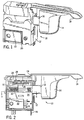
- a speed control 10 for a DC motor driven power tool has an enclosure 12 of an electrical insulating material, such as plastic.
- a trigger 14 projects from the enclosure on a shaft 16 which is movable into and out of the enclosure through an aperture.
- a direction control lever 18 which pivotally extends through another aperture of the enclosure 12. By pivoting the direction control lever 18 a user of the power tool is able to determine whether the motor of the tool is driven in a forward or a reverse direction.
- the degree to which the trigger 14 is pushed toward the enclosure 12 determines the rate at which the motor turns in the selected direction.
- the enclosure has an opening 20 through which a portion of the case of a metal oxide field effect transistor (MOSFET) 22 extends so that the case may be attached to an external heat sink within the power tool.
- MOSFET metal oxide field effect transistor
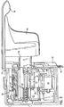
- FIG 2 illustrates the variable speed control 10 with the facing portion of the enclosure 12 removed in order to observe the internal assembly.
- the speed control lever 18 has an intermediate pin 24 which couples the external portion of the lever 18 to an internal lever portion 26.
- the internal lever portion 26 operates movable contacts of a double-pole double-throw (DPDT) direction control switch 28, which controls the direction that direct current from a battery flows through the motor of the power tool, and thus the direction that the motor rotates.
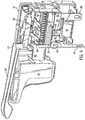
- the direction control switch 28 is shown in greater detail in Figures 3 and 4 and is connected to a pair of motor terminals 31 and 32, visible in Figure 4.
- DPDT double-pole double-throw
- a compression spring 30 biases the trigger shaft 16 outward from the enclosure 12 into a normal position at which the power tool is in the off state.
- the internal end of the trigger shaft 16 has a contact carrier 32.
- a wiper 34 for a potentiometer 64 of the variable speed control circuit 10 is mounted on one side of the contact carrier 32 (see Figure 3), so that the wiper 34 moves laterally within the enclosure 12 as the trigger is depressed and released.
- a contact 33 at one end of the wiper 34 rubs against a metal conductor on the surface of a printed circuit board 36 shown mounted in the enclosure in Figure 5 and a contact 35 at the other end moves across a resistive coating applied to the printed circuit board.
- a movable, or bridge, contact 38 of a function switch 39 is held on the opposite side of the trigger contact carrier 32.
- the movable contact 38 bridges different ones of a set of four stationary contacts 40, 41, 42, and 44 depending on the position of the trigger 14 and its contact carrier 32, as seen in Figure 5.
- a positive stationary contact 40 is connected to the positive battery terminal 46 of the variable speed control circuit and a negative stationary contact 44 is connected to the negative battery terminal 48.
- the contact carrier 32 pushes the movable contact 38 across the stationary switch contacts 40-44, as will be described.
- the variable speed control circuit 10 is electrically connected to the other components of the hand-held power tool as shown in Figure 6. Specifically, a battery 52 is connected across the battery terminals 46 and 48, and a DC motor 54 is connected to the motor terminals 31 and 32. The two motor terminals 31 and 32 are connected by separate switch sections of the DPDT motor direction control switch 28. One stationary contact of each switch pole is connected to the positive battery terminal 46 with the other stationary contact being connected to an intermediate node 51. A free wheeling diode 50 is connected between the positive battery terminal 46 and the intermediate node 51 in reverse biased direction.
- the source drain conduction path of the MOSFET 22 is connected between the intermediate node 51 and a circuit ground node 80.
- the circuit ground node 80 is connected to stationary contact 41 of the motor function switch 39, which is designated as the speed control (SC) contact.
- the remaining stationary contact 42 of the motor function switch 39 is designated as a bypass (BP) contact and is connected directly to the intermediate node 51.
- SC speed control
- BP bypass
- an oscillator 60 built around a pair of inverters 61 and 62, includes the potentiometer 64 having wiper 34 mounted on the contact carrier 32 of the trigger 14. Movement of the wiper 34 with the trigger changes the voltage divider formed by the potentiometer 64 and fixed resistors 66 and 68 of the oscillator. This action changes the duty cycle of the oscillator, i.e. the width of the pulses produced on output line 70 varies.
- the oscillator output signal is applied to the inputs of four inverters 72, 73, 74 and 75 connected in parallel with a common output coupled by resistor 78 to the gate electrode of the MOSFET 22.
- the parallel connected inverters 72-75 act as a current amplifier with the multiple devices serving to reduce the source impedance to drive the MOSFET 22.
- inverters are used, other types of buffers or amplifiers may be employed.
- the different inverters 61, 62 and 72-75 of the variable speed control circuit 10 are connected to a power supply 82 which derives the supply voltage VDD from the positive battery voltage at terminal 46.
- the spring 30 pushes the trigger assembly 14 to its full outward position transporting the movable bridge contact 38 to the off position illustrated is Figures 5 and 6.
- the contact carrier 32 of the trigger 14 transports the movable contact 38 in a direction shown by arrow 84 in these figures.
- the movable contact 38 travels to the edges of the positive and bypass stationary contacts 40 and 42, the movable contact rides onto a pair of insulating ridges 86 and 88 which protrude from the enclosure 12. This travel disengages the movable contact 38 from the stationary contacts 40-44 so that the gaps between adjacent stationary contacts will not be bridged by the movable contact.
- the movable contact will not short all four of the stationary contacts 40-44 together in an intermediate position of its travel. Further depression of the trigger 14 moves the movable contact 38 onto the speed control contact 41 and the negative battery contact 44. At this time, the negative terminal 48 is connected to the ground node 80 of the variable speed control circuit 10 and power is applied to the circuit components.
- the wiper 34 of potentiometer 64 assumes an initial position which causes the oscillator 60 to produce an output signal having a relatively long positive pulse during each oscillator cycle.
- the oscillator output signal is inverted by the parallel connected inverters 72-75, a signal is produced at node 76 which has a relatively short positive pulse during each signal cycle.
- this resultant signal is applied to the gate of the MOSFET 22, the transistor will be conductive for brief periods separated by relatively long non-conductive periods.
- the motor 54 receives short pulses of electric current and turns at a relatively slow speed.
- the direction of movement is set by the position of the direction control switch 28, with the forward position being illustrated.
- the movable contact 38 couples the bypass stationary contact 42 to the negative stationary contact 44. This connects the negative terminal 48 of the battery 52 directly to intermediate node 51 on one side of the motor 54. The other side of the motor always is connected directly to the positive battery terminal 46.
- the speed control stationary contact 41 is disconnected from the other contacts 40, 42, and 44 and power is removed from the oscillator 60 and the parallel connected inverters 72-75.
- the MOSFET 22 is turned off in the bypass mode as it is bypassed by the connection of contacts 42 and 44.
- the process of speed control is reversed as the user releases the trigger allowing it to move away from the enclosure 12.
- the movable contact 38 is traveling in the reverse direction to that indicated by arrow 84 and travels from a position where it is bridging stationary contacts 42 and 44 to where it again connects the speed control stationary contact 41 with the negative stationary contact 44.
- power is once again applied to the oscillator and to the parallel connected inverters 72-75. Further releasing of the trigger causes the motor speed to decrease in the reverse operation from that previously described to increase the speed.
Landscapes
- Control Of Direct Current Motors (AREA)
- Motor And Converter Starters (AREA)
- Stopping Of Electric Motors (AREA)
- Toys (AREA)
- Oscillators With Electromechanical Resonators (AREA)
Applications Claiming Priority (2)
| Application Number | Priority Date | Filing Date | Title |
|---|---|---|---|
| US76559 | 1998-05-12 | ||
| US09/076,559 US5892885A (en) | 1998-05-12 | 1998-05-12 | Variable speed control switch for direct current electric power tools |
Publications (3)
| Publication Number | Publication Date |
|---|---|
| EP0957497A2 true EP0957497A2 (de) | 1999-11-17 |
| EP0957497A3 EP0957497A3 (de) | 2000-08-23 |
| EP0957497B1 EP0957497B1 (de) | 2004-06-30 |
Family
ID=22132788
Family Applications (1)
| Application Number | Title | Priority Date | Filing Date |
|---|---|---|---|
| EP99109186A Expired - Lifetime EP0957497B1 (de) | 1998-05-12 | 1999-05-10 | Schalter zur Steuerung eines Gleichstromelektrowerkzeuges mit veränderlicher Geschwindigkeit |
Country Status (7)
| Country | Link |
|---|---|
| US (1) | US5892885A (de) |
| EP (1) | EP0957497B1 (de) |
| JP (1) | JP4206434B2 (de) |
| CN (1) | CN1087519C (de) |
| DE (1) | DE69918369T2 (de) |
| ES (1) | ES2222638T3 (de) |
| TW (1) | TW417124B (de) |
Cited By (1)
| Publication number | Priority date | Publication date | Assignee | Title |
|---|---|---|---|---|
| CN103578820B (zh) * | 2012-07-24 | 2017-04-26 | Abb股份公司 | 改进的固态开关装置 |
Families Citing this family (28)
| Publication number | Priority date | Publication date | Assignee | Title |
|---|---|---|---|---|
| US6501542B2 (en) * | 1998-06-30 | 2002-12-31 | Lj Laboratories, Llc | Apparatus and method for measuring optical characteristics of an object |
| US6774509B2 (en) * | 2002-01-30 | 2004-08-10 | Defond Manufacturing Limited | Electrical switch assembly |
| DE10214363A1 (de) * | 2002-03-30 | 2003-10-16 | Bosch Gmbh Robert | Kühlanordnung und Elektrogerät mit einer Kühlanordnung |
| CA2397024C (en) * | 2002-08-07 | 2008-02-19 | Edward M. Turley | Switch mechanism for reversible grinder |
| US6741051B2 (en) * | 2002-08-30 | 2004-05-25 | Defond Manufacturing Limited | Power tool trigger control |
| US7075257B2 (en) * | 2002-10-18 | 2006-07-11 | Black & Decker Inc. | Method and device for braking a motor |
| US7023159B2 (en) | 2002-10-18 | 2006-04-04 | Black & Decker Inc. | Method and device for braking a motor |
| US6736220B1 (en) * | 2003-05-22 | 2004-05-18 | Defond Components Limited | Power tool trigger assembly |
| US6717080B1 (en) * | 2003-05-22 | 2004-04-06 | Defond Components Limited | Power tool trigger assembly |
| US6749028B1 (en) * | 2003-05-22 | 2004-06-15 | Defond Components Limited | Power tool trigger assembly |
| DE602006013863D1 (de) * | 2005-11-04 | 2010-06-02 | Bosch Gmbh Robert | Verfahren und vorrichtung für einen gelenkbohrer |
| CN101699593B (zh) * | 2006-01-27 | 2012-06-13 | 上海拜骋电器有限公司 | 开关组件 |
| CN101256910B (zh) * | 2007-03-01 | 2011-05-18 | 苏州宝时得电动工具有限公司 | 电动工具开关及使用该开关的电动工具 |
| DE102008030813A1 (de) * | 2007-07-04 | 2009-01-08 | Marquardt Gmbh | Ansteuereinrichtung für einen Elektromotor |
| DE102009027111A1 (de) * | 2009-06-23 | 2010-12-30 | Robert Bosch Gmbh | Elektrische Werkzeugmaschine |
| US9406457B2 (en) | 2011-05-19 | 2016-08-02 | Black & Decker Inc. | Electronic switching module for a power tool |
| US8493172B2 (en) | 2011-09-30 | 2013-07-23 | Snap-On Incorporated | Variable speed toggle trigger |
| US8716962B2 (en) * | 2011-11-10 | 2014-05-06 | Snap-On Incorporated | Variable speed trigger mechanism |
| CN102751117A (zh) * | 2012-07-11 | 2012-10-24 | 乐清市杰拉华电器有限公司 | 电动工具的调速开关 |
| DE102012214030A1 (de) * | 2012-08-08 | 2014-02-13 | Robert Bosch Gmbh | Elektrisches Handwerkzeug mit diskretem Bedienelement |
| JP2014148006A (ja) * | 2013-02-01 | 2014-08-21 | Makita Corp | 電動工具及び携帯用マルノコ |
| CN103854900B (zh) * | 2014-03-10 | 2015-09-09 | 意拉德电子(东莞)有限公司 | 一种应用于直流无刷电机的电子式开关的构成方法 |
| DE102014112982A1 (de) * | 2014-09-09 | 2016-03-10 | Johnson Electric Germany GmbH & Co. KG | Elektrischer Schalter |
| CN104900426B (zh) * | 2014-12-31 | 2018-08-24 | 徐新生 | 一种电动工具中的电枢回路及电池组插座 |
| US10608501B2 (en) | 2017-05-24 | 2020-03-31 | Black & Decker Inc. | Variable-speed input unit having segmented pads for a power tool |
| TWI730281B (zh) | 2018-01-03 | 2021-06-11 | 美商米沃奇電子工具公司 | 電動工具中之電子制動技術 |
| JP6854302B2 (ja) * | 2018-01-10 | 2021-04-07 | ディーフォン エレクテック カンパニー リミテッドDefond Electech Co., Ltd | 電気的デバイスの可変速コントローラと共に使用する電気的スイッチモジュール |
| EP3809434A3 (de) * | 2019-10-15 | 2021-04-28 | Defond Electech Co., Ltd | Anordnung zur steuerung variabler drehmomente für eine elektrische vorrichtung |
Family Cites Families (16)
| Publication number | Priority date | Publication date | Assignee | Title |
|---|---|---|---|---|
| USRE22267E (en) * | 1943-02-16 | Tobque conveying and converting -apparatus | ||
| US3329842A (en) * | 1965-05-11 | 1967-07-04 | Cutler Hammer Inc | Speed controllers for portable devices |
| US3389365A (en) * | 1965-08-23 | 1968-06-18 | Lucerne Products Inc | Variable resistor with switch |
| US3536973A (en) * | 1968-02-01 | 1970-10-27 | Lucerne Products Inc | Switch and speed control for electric motor |
| GB1272933A (en) * | 1968-07-26 | 1972-05-03 | Clark Stacatruc Ltd | Pulse control systems for electric motors |
| US3739126A (en) * | 1971-06-01 | 1973-06-12 | Lucerne Products Inc | Switch assembly |
| US4508999A (en) * | 1983-01-05 | 1985-04-02 | Towmotor Corporation | Short circuit protection apparatus |
| US4555651A (en) * | 1983-01-05 | 1985-11-26 | Towmotor Corporation | Motor speed control apparatus |
| US4737661A (en) * | 1985-08-09 | 1988-04-12 | Black & Decker Inc. | Variable speed trigger switch |
| US4665290A (en) * | 1985-09-30 | 1987-05-12 | Eaton Corporation | Trigger operated portable electric tool switch |
| DE3882007T2 (de) * | 1987-10-21 | 1994-02-17 | Omron Tateisi Electronics Co | Elektrischer Schalter für Elektrowerkzeug. |
| US5003628A (en) * | 1989-03-02 | 1991-03-26 | Lucerne Products, Inc. | Variable speed D.C. motor control |
| DE4038786A1 (de) * | 1990-12-05 | 1992-06-11 | Bsg Schalttechnik | Vorrichtung zur steuerung oder regelung von durch akkus versorgter geraete |
| DE4114854A1 (de) * | 1991-05-07 | 1992-11-12 | Marquardt Gmbh | Schalter, insbesondere akku-schalter fuer handbetaetigte elektrowerkzeuge |
| US5198793A (en) * | 1991-07-30 | 1993-03-30 | Eaton Corporation | Electric control apparatus comprising integral electrical conductors plated on a two-shot molded plastic insulating housing |
| US5380971A (en) * | 1992-11-09 | 1995-01-10 | Lucerne Products, Inc. | Dynamic brake switch for motor |
-
1998
- 1998-05-12 US US09/076,559 patent/US5892885A/en not_active Expired - Fee Related
-
1999
- 1999-04-16 TW TW088106088A patent/TW417124B/zh not_active IP Right Cessation
- 1999-05-07 JP JP12693399A patent/JP4206434B2/ja not_active Expired - Fee Related
- 1999-05-10 EP EP99109186A patent/EP0957497B1/de not_active Expired - Lifetime
- 1999-05-10 DE DE69918369T patent/DE69918369T2/de not_active Expired - Fee Related
- 1999-05-10 ES ES99109186T patent/ES2222638T3/es not_active Expired - Lifetime
- 1999-05-12 CN CN99106392.9A patent/CN1087519C/zh not_active Expired - Fee Related
Cited By (1)
| Publication number | Priority date | Publication date | Assignee | Title |
|---|---|---|---|---|
| CN103578820B (zh) * | 2012-07-24 | 2017-04-26 | Abb股份公司 | 改进的固态开关装置 |
Also Published As
| Publication number | Publication date |
|---|---|
| EP0957497B1 (de) | 2004-06-30 |
| DE69918369T2 (de) | 2005-08-18 |
| ES2222638T3 (es) | 2005-02-01 |
| US5892885A (en) | 1999-04-06 |
| JPH11341876A (ja) | 1999-12-10 |
| EP0957497A3 (de) | 2000-08-23 |
| DE69918369D1 (de) | 2004-08-05 |
| CN1087519C (zh) | 2002-07-10 |
| CN1239349A (zh) | 1999-12-22 |
| TW417124B (en) | 2001-01-01 |
| JP4206434B2 (ja) | 2009-01-14 |
Similar Documents
| Publication | Publication Date | Title |
|---|---|---|
| US5892885A (en) | Variable speed control switch for direct current electric power tools | |
| US7652442B2 (en) | Electric tool switch mechanism | |
| US3536973A (en) | Switch and speed control for electric motor | |
| US4719395A (en) | Variable speed control switch for an electric tool including a DC motor | |
| US20020158593A1 (en) | Circuit for controlling dynamic braking of a motor shaft in a power tool | |
| JPH10295091A (ja) | 電動モーターの制動装置及び方法 | |
| US4459522A (en) | Circuit arrangement for counterclockwise and clockwise rotation of commutator motors | |
| US4903318A (en) | Electric switch system for a power tool | |
| US4995094A (en) | DC motor control circuit providing variable speed operation | |
| WO2001054263A8 (en) | Motor control apparatus for a railway switch machine | |
| CN109935429A (zh) | 用于电气设备的变速控制器 | |
| US10998805B2 (en) | Power tool with direction sensing controller | |
| JP2922294B2 (ja) | フライバック電流減衰装置 | |
| JP4726904B2 (ja) | スイッチ回路 | |
| US6483268B1 (en) | DC motor brake | |
| US5003628A (en) | Variable speed D.C. motor control | |
| GB2391708A (en) | Rocker switch | |
| JP3073751B2 (ja) | レンズ駆動装置 | |
| US20090102404A1 (en) | Control Circuit For An Electromotor With Electronic Brake Switch | |
| US4734547A (en) | Reversing speed control switch | |
| US20250285819A1 (en) | Electrical switch unit for electrical device | |
| JPH0644437B2 (ja) | 電動工具用モ−タの正逆切換え構造 | |
| JP2829991B2 (ja) | 電流制限回路 | |
| JP2770614B2 (ja) | リレー回路 | |
| JPS6114317Y2 (de) |
Legal Events
| Date | Code | Title | Description |
|---|---|---|---|
| PUAI | Public reference made under article 153(3) epc to a published international application that has entered the european phase |
Free format text: ORIGINAL CODE: 0009012 |
|
| AK | Designated contracting states |
Kind code of ref document: A2 Designated state(s): DE ES GB |
|
| AX | Request for extension of the european patent |
Free format text: AL;LT;LV;MK;RO;SI |
|
| PUAL | Search report despatched |
Free format text: ORIGINAL CODE: 0009013 |
|
| AK | Designated contracting states |
Kind code of ref document: A3 Designated state(s): AT BE CH CY DE DK ES FI FR GB GR IE IT LI LU MC NL PT SE |
|
| AX | Request for extension of the european patent |
Free format text: AL;LT;LV;MK;RO;SI |
|
| 17P | Request for examination filed |
Effective date: 20000811 |
|
| AKX | Designation fees paid |
Free format text: DE ES GB |
|
| 17Q | First examination report despatched |
Effective date: 20030410 |
|
| GRAP | Despatch of communication of intention to grant a patent |
Free format text: ORIGINAL CODE: EPIDOSNIGR1 |
|
| GRAS | Grant fee paid |
Free format text: ORIGINAL CODE: EPIDOSNIGR3 |
|
| GRAA | (expected) grant |
Free format text: ORIGINAL CODE: 0009210 |
|
| AK | Designated contracting states |
Kind code of ref document: B1 Designated state(s): DE ES GB |
|
| REG | Reference to a national code |
Ref country code: GB Ref legal event code: FG4D |
|
| REF | Corresponds to: |
Ref document number: 69918369 Country of ref document: DE Date of ref document: 20040805 Kind code of ref document: P |
|
| REG | Reference to a national code |
Ref country code: ES Ref legal event code: FG2A Ref document number: 2222638 Country of ref document: ES Kind code of ref document: T3 |
|
| PLBE | No opposition filed within time limit |
Free format text: ORIGINAL CODE: 0009261 |
|
| STAA | Information on the status of an ep patent application or granted ep patent |
Free format text: STATUS: NO OPPOSITION FILED WITHIN TIME LIMIT |
|
| 26N | No opposition filed |
Effective date: 20050331 |
|
| PGFP | Annual fee paid to national office [announced via postgrant information from national office to epo] |
Ref country code: ES Payment date: 20090526 Year of fee payment: 11 |
|
| PGFP | Annual fee paid to national office [announced via postgrant information from national office to epo] |
Ref country code: DE Payment date: 20090528 Year of fee payment: 11 |
|
| PGFP | Annual fee paid to national office [announced via postgrant information from national office to epo] |
Ref country code: GB Payment date: 20090528 Year of fee payment: 11 |
|
| GBPC | Gb: european patent ceased through non-payment of renewal fee |
Effective date: 20100510 |
|
| PG25 | Lapsed in a contracting state [announced via postgrant information from national office to epo] |
Ref country code: DE Free format text: LAPSE BECAUSE OF NON-PAYMENT OF DUE FEES Effective date: 20101201 |
|
| REG | Reference to a national code |
Ref country code: ES Ref legal event code: FD2A Effective date: 20110718 |
|
| PG25 | Lapsed in a contracting state [announced via postgrant information from national office to epo] |
Ref country code: GB Free format text: LAPSE BECAUSE OF NON-PAYMENT OF DUE FEES Effective date: 20100510 Ref country code: ES Free format text: LAPSE BECAUSE OF NON-PAYMENT OF DUE FEES Effective date: 20110706 |
|
| PG25 | Lapsed in a contracting state [announced via postgrant information from national office to epo] |
Ref country code: ES Free format text: LAPSE BECAUSE OF NON-PAYMENT OF DUE FEES Effective date: 20100511 |