EP0957499B1 - Commutateur multiple a levier - Google Patents
Commutateur multiple a levier Download PDFInfo
- Publication number
- EP0957499B1 EP0957499B1 EP98901009A EP98901009A EP0957499B1 EP 0957499 B1 EP0957499 B1 EP 0957499B1 EP 98901009 A EP98901009 A EP 98901009A EP 98901009 A EP98901009 A EP 98901009A EP 0957499 B1 EP0957499 B1 EP 0957499B1
- Authority
- EP
- European Patent Office
- Prior art keywords
- connector
- insulator
- switch
- lever combination
- combination switch
- Prior art date
- Legal status (The legal status is an assumption and is not a legal conclusion. Google has not performed a legal analysis and makes no representation as to the accuracy of the status listed.)
- Expired - Lifetime
Links
- 239000012212 insulator Substances 0.000 claims description 31
- XEEYBQQBJWHFJM-UHFFFAOYSA-N Iron Chemical compound [Fe] XEEYBQQBJWHFJM-UHFFFAOYSA-N 0.000 description 4
- 238000000465 moulding Methods 0.000 description 3
- 229910052742 iron Inorganic materials 0.000 description 2
- 238000010276 construction Methods 0.000 description 1
Images

Classifications
-
- H—ELECTRICITY
- H01—ELECTRIC ELEMENTS
- H01H—ELECTRIC SWITCHES; RELAYS; SELECTORS; EMERGENCY PROTECTIVE DEVICES
- H01H25/00—Switches with compound movement of handle or other operating part
- H01H25/04—Operating part movable angularly in more than one plane, e.g. joystick
-
- H—ELECTRICITY
- H01—ELECTRIC ELEMENTS
- H01R—ELECTRICALLY-CONDUCTIVE CONNECTIONS; STRUCTURAL ASSOCIATIONS OF A PLURALITY OF MUTUALLY-INSULATED ELECTRICAL CONNECTING ELEMENTS; COUPLING DEVICES; CURRENT COLLECTORS
- H01R13/00—Details of coupling devices of the kinds covered by groups H01R12/70 or H01R24/00 - H01R33/00
- H01R13/66—Structural association with built-in electrical component
- H01R13/70—Structural association with built-in electrical component with built-in switch
-
- B—PERFORMING OPERATIONS; TRANSPORTING
- B60—VEHICLES IN GENERAL
- B60Q—ARRANGEMENT OF SIGNALLING OR LIGHTING DEVICES, THE MOUNTING OR SUPPORTING THEREOF OR CIRCUITS THEREFOR, FOR VEHICLES IN GENERAL
- B60Q1/00—Arrangement of optical signalling or lighting devices, the mounting or supporting thereof or circuits therefor
- B60Q1/02—Arrangement of optical signalling or lighting devices, the mounting or supporting thereof or circuits therefor the devices being primarily intended to illuminate the way ahead or to illuminate other areas of way or environments
- B60Q1/04—Arrangement of optical signalling or lighting devices, the mounting or supporting thereof or circuits therefor the devices being primarily intended to illuminate the way ahead or to illuminate other areas of way or environments the devices being headlights
- B60Q1/14—Arrangement of optical signalling or lighting devices, the mounting or supporting thereof or circuits therefor the devices being primarily intended to illuminate the way ahead or to illuminate other areas of way or environments the devices being headlights having dimming means
- B60Q1/1446—Arrangement of optical signalling or lighting devices, the mounting or supporting thereof or circuits therefor the devices being primarily intended to illuminate the way ahead or to illuminate other areas of way or environments the devices being headlights having dimming means controlled by mechanically actuated switches
- B60Q1/1453—Hand actuated switches
- B60Q1/1461—Multifunction switches for dimming headlights and controlling additional devices, e.g. for controlling direction indicating lights
- B60Q1/1469—Multifunction switches for dimming headlights and controlling additional devices, e.g. for controlling direction indicating lights controlled by or attached to a single lever, e.g. steering column stalk switches
- B60Q1/1476—Multifunction switches for dimming headlights and controlling additional devices, e.g. for controlling direction indicating lights controlled by or attached to a single lever, e.g. steering column stalk switches comprising switch controlling means located near the free end of the lever, e.g. press buttons, rotatable rings
-
- H—ELECTRICITY
- H01—ELECTRIC ELEMENTS
- H01H—ELECTRIC SWITCHES; RELAYS; SELECTORS; EMERGENCY PROTECTIVE DEVICES
- H01H1/00—Contacts
- H01H1/58—Electric connections to or between contacts; Terminals
Definitions
- This invention relates to a lever combination switch mounted on a steering shaft in a vehicle.
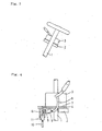
- a bracket 2 made of an iron plate, is mounted on a steering shaft 1, and a switch case 3 is fixedly secured to this bracket 2.
- An insulator 4 is interposed between a bottom of this switch case 3 and the bracket 2.
- Two female connectors 5 and 6 are formed at the insulator 4, and a terminal 7, embedded therein by insert molding, projects into the female connectors 5 and 6.
- EPO 399 895 discloses a lever combination switch wherein a bottom of a switch case is fixed to a bracket, mounted on a steering shaft.
- a lever combination switch wherein a bottom of a switch case is fixed to a bracket, mounted on a steering shaft, through an insulator interposed therebetween, CHARACTERIZED in that the insulator comprises a lower insulator, having at its reverse side a lower connector for connection to a connector connected to a vehicle-side circuit, and an upper insulator which has at its obverse side an upper connector for connection to a connector, connected to a switch case-side circuit, and the upper insulator also has a terminal, which projects from a reverse surface of the upper insulator, and is connected to the lower connector, and the upper insulator is disposed in superposing relation to the lower connector.
- the upper connector for connection to the connector, connected to the switch case-side circuit is formed on the obverse side of the upper insulator, and only the lower connector for connection to the connector, connected to the vehicle-side circuit, is formed on the reverse side of the lower insulator. Therefore, a connector space at the reverse side of the bottom of the switch case can be saved, and such saved space is used for the mounting of the bracket, and by doing so, the size of the bracket can be increased, thereby increasing the strength thereof.
- Fig. 1 shows one embodiment of a lever combination switch 20 of the present invention.
- This lever combination switch 20 comprises a bracket 22, which is made of an iron plate, and is mounted on a steering shaft 21, a switch case 24 having a wiper switch lever 23, an upper insulator 25 and a lower insulator 26, the upper and lower insulators being interposed in a superposed manner between a bottom of the switch case 24 and the bracket 22.
- a terminal 33 projecting into the lower female connector 29, is embedded in the lower insulator 26 by insert molding.
- a terminal 34 is embedded in the upper insulator 25 by insert molding, and one end portion 34a, branching from the terminal 34, projects into the upper female connector 32, and the other end portion 34b projects from the reverse surface of the upper insulator, and when the two insulators 25 and 26 are superposed together, the other end portion 34b projects into the lower female connector 29.
- the lever combination switch 20 of this embodiment has the above construction, and the upper connector 32 for connection to the male connector 31, connected through the cord 30 to the switch case 24, is formed on the obverse side of the upper insulator 25, and only the lower connector 29 for connection to the male connector 28, connected through the cord 27 to the vehicle-side circuit, is formed on the reverse side of the lower insulator 26. Therefore, as compared with the conventional lever combination switch in which the two male connectors are connected at the reverse side of the bottom of the switch case 24, a connector space at the reverse side of the bottom of the switch case 24 can be saved, and such saved space is used for the mounting of the bracket 22, and by doing so, the size of the bracket can be increased, thereby increasing the strength.
Landscapes
- Engineering & Computer Science (AREA)
- Mechanical Engineering (AREA)
- Physics & Mathematics (AREA)
- Electromagnetism (AREA)
- Switches With Compound Operations (AREA)
- Switch Cases, Indication, And Locking (AREA)
Claims (1)
- Commutateur combiné à levier dans lequel une partie inférieure d'un boîtier de commutateur est fixée sur un support (22), monté sur un arbre de direction (21), par un isolant (25, 26) interposé entre eux, caractérisé en ce que ledit isolant (25, 26) comporte un isolant inférieur (26) ayant sur son côté arrière un connecteur inférieur (29) pour connexion à un connecteur (28) connecté à un circuit côté véhicule, et un isolant supérieur (25) qui a sur son côté supérieur un connecteur supérieur (32) pour connexion à un connecteur, connecté à un circuit côté boîtier de commutateur, et ledit isolant supérieur (25) a également une borne (34), qui fait saillie à partir d'une surface arrière dudit isolant supérieur (25), et est connectée audit connecteur inférieur (29), et ledit isolant supérieur (25) est disposé dans une relation de superposition par rapport audit connecteur inférieur (29).
Applications Claiming Priority (3)
| Application Number | Priority Date | Filing Date | Title |
|---|---|---|---|
| JP03265797A JP3318502B2 (ja) | 1997-01-31 | 1997-01-31 | レバーコンビネーションスイッチ |
| JP3265797 | 1997-01-31 | ||
| PCT/JP1998/000328 WO1998034255A1 (fr) | 1997-01-31 | 1998-01-28 | Commutateur multiple a levier |
Publications (3)
| Publication Number | Publication Date |
|---|---|
| EP0957499A1 EP0957499A1 (fr) | 1999-11-17 |
| EP0957499A4 EP0957499A4 (fr) | 2006-06-14 |
| EP0957499B1 true EP0957499B1 (fr) | 2007-07-04 |
Family
ID=12364945
Family Applications (1)
| Application Number | Title | Priority Date | Filing Date |
|---|---|---|---|
| EP98901009A Expired - Lifetime EP0957499B1 (fr) | 1997-01-31 | 1998-01-28 | Commutateur multiple a levier |
Country Status (6)
| Country | Link |
|---|---|
| US (1) | US6162063A (fr) |
| EP (1) | EP0957499B1 (fr) |
| JP (1) | JP3318502B2 (fr) |
| KR (1) | KR100336406B1 (fr) |
| DE (1) | DE69838020T2 (fr) |
| WO (1) | WO1998034255A1 (fr) |
Family Cites Families (9)
| Publication number | Priority date | Publication date | Assignee | Title |
|---|---|---|---|---|
| EP0399895B1 (fr) * | 1989-05-23 | 1994-10-12 | Valeo Electronique | Platine de servitude associée au tableau de bord d'un véhicule automobile |
| JP2778856B2 (ja) * | 1991-07-10 | 1998-07-23 | 住友電装株式会社 | 小型ジャンクションボックス |
| JPH0549517A (ja) * | 1991-08-21 | 1993-03-02 | Misawa Homes Co Ltd | 収納装置 |
| JP2567289Y2 (ja) * | 1991-12-13 | 1998-04-02 | ナイルス部品株式会社 | 車両用コンビネーションスイッチの取付構造 |
| JP2710911B2 (ja) * | 1993-05-31 | 1998-02-10 | アルプス電気株式会社 | ケーブルリール |
| FR2710597B1 (fr) * | 1993-10-01 | 1995-11-24 | Valeo Electronique | Contacteur tournant pour véhicule automobile. |
| JP2924672B2 (ja) * | 1994-11-16 | 1999-07-26 | 住友電装株式会社 | 電気接続箱 |
| US5771151A (en) * | 1996-07-10 | 1998-06-23 | The Whitaker Corporation | Central electrical assembly |
| DE19649857C1 (de) * | 1996-12-02 | 1998-03-12 | Kostal Leopold Gmbh & Co Kg | Funktionsmodul |
-
1997
- 1997-01-31 JP JP03265797A patent/JP3318502B2/ja not_active Expired - Fee Related
-
1998
- 1998-01-28 US US09/355,559 patent/US6162063A/en not_active Expired - Lifetime
- 1998-01-28 KR KR1019997006840A patent/KR100336406B1/ko not_active Expired - Fee Related
- 1998-01-28 DE DE69838020T patent/DE69838020T2/de not_active Expired - Lifetime
- 1998-01-28 EP EP98901009A patent/EP0957499B1/fr not_active Expired - Lifetime
- 1998-01-28 WO PCT/JP1998/000328 patent/WO1998034255A1/fr not_active Ceased
Also Published As
| Publication number | Publication date |
|---|---|
| JP3318502B2 (ja) | 2002-08-26 |
| JPH10223096A (ja) | 1998-08-21 |
| KR20000070593A (ko) | 2000-11-25 |
| US6162063A (en) | 2000-12-19 |
| EP0957499A1 (fr) | 1999-11-17 |
| EP0957499A4 (fr) | 2006-06-14 |
| DE69838020D1 (de) | 2007-08-16 |
| WO1998034255A1 (fr) | 1998-08-06 |
| DE69838020T2 (de) | 2007-11-22 |
| KR100336406B1 (ko) | 2002-05-10 |
Similar Documents
| Publication | Publication Date | Title |
|---|---|---|
| US6042431A (en) | Joint device for an automotive wiring harness | |
| US5033326A (en) | Shaft for manually guided lift vehicles and lift loaders | |
| EP0895304A3 (fr) | Connecteur jack de communication à haute fréquence | |
| EP1209772A3 (fr) | Contact suprimant la décharge en arc, méthode pour le produire et connecteur suprimant la décharge en arc | |
| US5548488A (en) | Electrical componet mounting system | |
| EP1174958A3 (fr) | Connecteur coaxial et dispositif de communication ayant un tel connecteur | |
| US5951311A (en) | Rotary connector | |
| US6319013B2 (en) | Wiring structure for motorcycle with busbars | |
| EP0861753B1 (fr) | Ensemble de commutateurs | |
| EP0810696A3 (fr) | Connecteur pour plaque à circuit imprimé | |
| EP0805077A3 (fr) | Interrupteur principal d'un véhicule | |
| US6368131B1 (en) | Waterproof electrical connector | |
| EP0957499B1 (fr) | Commutateur multiple a levier | |
| US6261105B1 (en) | Electric connection box | |
| US6150614A (en) | Conducting foil for conductively connecting electric and/or electronic components | |
| US4801279A (en) | Shape memory alloy spring connection asssembly | |
| EP1202309A3 (fr) | Dispositif de verrouillage pour plusieurs interrupteurs à bouton-poussoir | |
| KR200248172Y1 (ko) | 휴대폰 충전기의 단자 고정구조 | |
| EP0867953A1 (fr) | Connecteur pour borne de batterie | |
| US5892295A (en) | Fuse apparatus for a vehicle | |
| EP0924810A3 (fr) | Connecteur d' antenne coaxiale pour un téléphone portable | |
| JP2567581Y2 (ja) | キー装置 | |
| CN2356436Y (zh) | 改良的有线电视同轴讯号转接器 | |
| KR100240711B1 (ko) | 리어 윈도우 글래스 안테나의 터미널 연결장치 | |
| KR200255089Y1 (ko) | 볼륨스위치의 고정판구조 |
Legal Events
| Date | Code | Title | Description |
|---|---|---|---|
| PUAI | Public reference made under article 153(3) epc to a published international application that has entered the european phase |
Free format text: ORIGINAL CODE: 0009012 |
|
| 17P | Request for examination filed |
Effective date: 19990730 |
|
| AK | Designated contracting states |
Kind code of ref document: A1 Designated state(s): DE GB |
|
| A4 | Supplementary search report drawn up and despatched |
Effective date: 20060427 |
|
| GRAP | Despatch of communication of intention to grant a patent |
Free format text: ORIGINAL CODE: EPIDOSNIGR1 |
|
| GRAS | Grant fee paid |
Free format text: ORIGINAL CODE: EPIDOSNIGR3 |
|
| GRAA | (expected) grant |
Free format text: ORIGINAL CODE: 0009210 |
|
| AK | Designated contracting states |
Kind code of ref document: B1 Designated state(s): DE GB |
|
| REG | Reference to a national code |
Ref country code: GB Ref legal event code: FG4D |
|
| REF | Corresponds to: |
Ref document number: 69838020 Country of ref document: DE Date of ref document: 20070816 Kind code of ref document: P |
|
| PLBE | No opposition filed within time limit |
Free format text: ORIGINAL CODE: 0009261 |
|
| STAA | Information on the status of an ep patent application or granted ep patent |
Free format text: STATUS: NO OPPOSITION FILED WITHIN TIME LIMIT |
|
| 26N | No opposition filed |
Effective date: 20080407 |
|
| PGFP | Annual fee paid to national office [announced via postgrant information from national office to epo] |
Ref country code: GB Payment date: 20100202 Year of fee payment: 13 Ref country code: DE Payment date: 20100121 Year of fee payment: 13 |
|
| GBPC | Gb: european patent ceased through non-payment of renewal fee |
Effective date: 20110128 |
|
| PG25 | Lapsed in a contracting state [announced via postgrant information from national office to epo] |
Ref country code: GB Free format text: LAPSE BECAUSE OF NON-PAYMENT OF DUE FEES Effective date: 20110128 |
|
| REG | Reference to a national code |
Ref country code: DE Ref legal event code: R119 Ref document number: 69838020 Country of ref document: DE Effective date: 20110802 |
|
| PG25 | Lapsed in a contracting state [announced via postgrant information from national office to epo] |
Ref country code: DE Free format text: LAPSE BECAUSE OF NON-PAYMENT OF DUE FEES Effective date: 20110802 |