EP0957568B1 - Alimentation de puissance à découpage du type à résonance de courant - Google Patents
Alimentation de puissance à découpage du type à résonance de courant Download PDFInfo
- Publication number
- EP0957568B1 EP0957568B1 EP99400934A EP99400934A EP0957568B1 EP 0957568 B1 EP0957568 B1 EP 0957568B1 EP 99400934 A EP99400934 A EP 99400934A EP 99400934 A EP99400934 A EP 99400934A EP 0957568 B1 EP0957568 B1 EP 0957568B1
- Authority
- EP
- European Patent Office
- Prior art keywords
- power source
- rectifying
- voltage
- current
- switching power
- Prior art date
- Legal status (The legal status is an assumption and is not a legal conclusion. Google has not performed a legal analysis and makes no representation as to the accuracy of the status listed.)
- Expired - Lifetime
Links
Images

Classifications
-
- H—ELECTRICITY
- H02—GENERATION; CONVERSION OR DISTRIBUTION OF ELECTRIC POWER
- H02M—APPARATUS FOR CONVERSION BETWEEN AC AND AC, BETWEEN AC AND DC, OR BETWEEN DC AND DC, AND FOR USE WITH MAINS OR SIMILAR POWER SUPPLY SYSTEMS; CONVERSION OF DC OR AC INPUT POWER INTO SURGE OUTPUT POWER; CONTROL OR REGULATION THEREOF
- H02M3/00—Conversion of DC power input into DC power output
- H02M3/22—Conversion of DC power input into DC power output with intermediate conversion into AC
- H02M3/24—Conversion of DC power input into DC power output with intermediate conversion into AC by static converters
- H02M3/28—Conversion of DC power input into DC power output with intermediate conversion into AC by static converters using discharge tubes with control electrode or semiconductor devices with control electrode to produce the intermediate AC
- H02M3/325—Conversion of DC power input into DC power output with intermediate conversion into AC by static converters using discharge tubes with control electrode or semiconductor devices with control electrode to produce the intermediate AC using devices of a triode or a transistor type requiring continuous application of a control signal
- H02M3/335—Conversion of DC power input into DC power output with intermediate conversion into AC by static converters using discharge tubes with control electrode or semiconductor devices with control electrode to produce the intermediate AC using devices of a triode or a transistor type requiring continuous application of a control signal using semiconductor devices only
- H02M3/33569—Conversion of DC power input into DC power output with intermediate conversion into AC by static converters using discharge tubes with control electrode or semiconductor devices with control electrode to produce the intermediate AC using devices of a triode or a transistor type requiring continuous application of a control signal using semiconductor devices only having several active switching elements
- H02M3/33576—Conversion of DC power input into DC power output with intermediate conversion into AC by static converters using discharge tubes with control electrode or semiconductor devices with control electrode to produce the intermediate AC using devices of a triode or a transistor type requiring continuous application of a control signal using semiconductor devices only having several active switching elements having at least one active switching element at the secondary side of an isolation transformer
- H02M3/33592—Conversion of DC power input into DC power output with intermediate conversion into AC by static converters using discharge tubes with control electrode or semiconductor devices with control electrode to produce the intermediate AC using devices of a triode or a transistor type requiring continuous application of a control signal using semiconductor devices only having several active switching elements having at least one active switching element at the secondary side of an isolation transformer having a synchronous rectifier circuit or a synchronous freewheeling circuit at the secondary side of an isolation transformer
-
- H—ELECTRICITY
- H02—GENERATION; CONVERSION OR DISTRIBUTION OF ELECTRIC POWER
- H02M—APPARATUS FOR CONVERSION BETWEEN AC AND AC, BETWEEN AC AND DC, OR BETWEEN DC AND DC, AND FOR USE WITH MAINS OR SIMILAR POWER SUPPLY SYSTEMS; CONVERSION OF DC OR AC INPUT POWER INTO SURGE OUTPUT POWER; CONTROL OR REGULATION THEREOF
- H02M3/00—Conversion of DC power input into DC power output
- H02M3/02—Conversion of DC power input into DC power output without intermediate conversion into AC
- H02M3/04—Conversion of DC power input into DC power output without intermediate conversion into AC by static converters
- H02M3/10—Conversion of DC power input into DC power output without intermediate conversion into AC by static converters using discharge tubes with control electrode or semiconductor devices with control electrode
- H02M3/125—Conversion of DC power input into DC power output without intermediate conversion into AC by static converters using discharge tubes with control electrode or semiconductor devices with control electrode using devices of a thyratron or thyristor type requiring extinguishing means
- H02M3/135—Conversion of DC power input into DC power output without intermediate conversion into AC by static converters using discharge tubes with control electrode or semiconductor devices with control electrode using devices of a thyratron or thyristor type requiring extinguishing means using semiconductor devices only
-
- Y—GENERAL TAGGING OF NEW TECHNOLOGICAL DEVELOPMENTS; GENERAL TAGGING OF CROSS-SECTIONAL TECHNOLOGIES SPANNING OVER SEVERAL SECTIONS OF THE IPC; TECHNICAL SUBJECTS COVERED BY FORMER USPC CROSS-REFERENCE ART COLLECTIONS [XRACs] AND DIGESTS
- Y02—TECHNOLOGIES OR APPLICATIONS FOR MITIGATION OR ADAPTATION AGAINST CLIMATE CHANGE
- Y02B—CLIMATE CHANGE MITIGATION TECHNOLOGIES RELATED TO BUILDINGS, e.g. HOUSING, HOUSE APPLIANCES OR RELATED END-USER APPLICATIONS
- Y02B70/00—Technologies for an efficient end-user side electric power management and consumption
- Y02B70/10—Technologies improving the efficiency by using switched-mode power supplies [SMPS], i.e. efficient power electronics conversion e.g. power factor correction or reduction of losses in power supplies or efficient standby modes
Definitions
- the present invention relates to a switching power source circuit and more particularly to a switching power source which is useful when an output voltage to be obtained on a secondary side in a current resonance type switching power source is used as a synchronous rectifying method.
- a dc-dc converter where high efficiency is maintained and noises are small even with a low voltage output, has been requested.
- the control voltage detection delay causes the timing at which both rectifying devices Q3 and Q4 are turned off, resulting in the problem where conduction angle of rectifying current is narrower, against which electric power transferring rate should be lowered by lowering the power factor.
- the rectifying device whose output voltage of the secondary winding is positive is turned on.
- the switching power source of the synchronous rectification type can be constructed by a small number of parts.
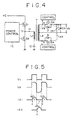
- control signal to drive the rectifying device can be supplied in a state where the primary side is insulated from the secondary side without transmitting via the transformer.
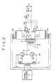
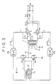
- a rectifying device of a synchronous rectification type is adapted to a current resonance type switching power source of a half bridge type
- a drive signal of the switching power source is supplied to the synchronous rectifying device. Therefore, a rectifying operation can efficiently be executed in no need of a specific circuit.
Landscapes
- Engineering & Computer Science (AREA)
- Power Engineering (AREA)
- Dc-Dc Converters (AREA)
- Rectifiers (AREA)
Claims (3)
- Alimentation de commutation par résonance de courant possédant un circuit d'entraínement pour alternativement mettre en marche/arrêt des éléments de commutation (Q1, Q2) qui sont connectés par demi-pont à un courant continu, dans laquelle une tension alternative est appliquée depuis un noeud desdits éléments de commutation (Q1, Q2) à un côté primaire (L1) d'un transformateur d'isolation (T) par l'intermédiaire d'un condensateur de résonance (C1), permettant ainsi d'obtenir une tension alternative prédéterminée depuis un enroulement secondaire (L2) dudit transformateur d'isolation (T), dans lequel
une paire de dispositifs de rectification (Q3, Q4) qui sont contrôlés suivant un cycle temporel de manière à être alternativement mis en marche sont prévus sur un côté de sortie dudit enroulement secondaire (L2), et
un signal de contrôle marche/arrêt de ladite paire de dispositifs de rectification (Q3, Q4) est délivré depuis une source de signal pour mettre en marche/arrêt lesdits éléments de commutation (Q1, Q2),
caractérisée en ce que ledit signal de contrôle marche/arrêt est délivré à une électrode de grille des dispositifs de rectification (Q3, Q4) par l'intermédiaire d'éléments de conversion photoélectriques (Pa, Pb) et de résistances (r1, r2), lesdites résistances fixant le cycle de marche au moyen d'une constante de temps propre à la capacité de la grille. - Alimentation de commutation par résonance de courant selon la revendication 1, dans laquelle lesdits éléments de commutation (Q1, Q2) et lesdits dispositifs de rectification (Q3, Q4) comprennent des transistors.
- Alimentation de commutation par résonance de courant selon la revendication 1 ou 2, dans laquelle un condensateur de filtrage (Co) est chargé avec le courant de rectification par l'intermédiaire d'une bobine d'arrêt (Lc) pour conduire lesdits dispositifs de rectification (Q3, Q4).
Applications Claiming Priority (2)
| Application Number | Priority Date | Filing Date | Title |
|---|---|---|---|
| JP10612498 | 1998-04-16 | ||
| JP10106124A JPH11299232A (ja) | 1998-04-16 | 1998-04-16 | 電流共振型スイッチング電源 |
Publications (3)
| Publication Number | Publication Date |
|---|---|
| EP0957568A2 EP0957568A2 (fr) | 1999-11-17 |
| EP0957568A3 EP0957568A3 (fr) | 2000-05-10 |
| EP0957568B1 true EP0957568B1 (fr) | 2004-11-17 |
Family
ID=14425690
Family Applications (1)
| Application Number | Title | Priority Date | Filing Date |
|---|---|---|---|
| EP99400934A Expired - Lifetime EP0957568B1 (fr) | 1998-04-16 | 1999-04-16 | Alimentation de puissance à découpage du type à résonance de courant |
Country Status (6)
| Country | Link |
|---|---|
| US (1) | US6072701A (fr) |
| EP (1) | EP0957568B1 (fr) |
| JP (1) | JPH11299232A (fr) |
| KR (1) | KR100623555B1 (fr) |
| CN (1) | CN1135681C (fr) |
| DE (1) | DE69921883T2 (fr) |
Families Citing this family (24)
| Publication number | Priority date | Publication date | Assignee | Title |
|---|---|---|---|---|
| EP1041706A1 (fr) * | 1999-03-29 | 2000-10-04 | Alcatel | Convertisseur à récupération et redressement synchrone avec tensions d'entrée et sortie variables |
| US6288919B1 (en) * | 1999-12-16 | 2001-09-11 | Chippower.Com, Inc. | Single stage AC/DC converter high frequency AC distribution systems |
| US6385056B1 (en) * | 2000-09-29 | 2002-05-07 | Jeff Gucyski | Precision switching power amplifier and uninterruptible power system |
| EP1356575B1 (fr) * | 2001-02-01 | 2007-05-02 | Power-One, Inc. | Circuits de commande isoles utilises dans des convertisseurs de secteur en mode commutation |
| US7102898B2 (en) | 2001-02-01 | 2006-09-05 | Di/Dt, Inc. | Isolated drive circuitry used in switch-mode power converters |
| DE10119283A1 (de) * | 2001-04-20 | 2002-10-24 | Philips Corp Intellectual Pty | System zur drahtlosen Übertragung elektrischer Leistung, ein Kleidungsstück, ein System von Kleidungsstücken und Verfahren zum Übertragen von Signalen und/oder elektrischer Leistung |
| US6597587B1 (en) * | 2002-04-02 | 2003-07-22 | The University Of Hong Kong | Current driven synchronous rectifier with energy recovery using hysterisis driver |
| JP2004135490A (ja) * | 2002-08-09 | 2004-04-30 | Sony Corp | スイッチング電源回路 |
| US6838859B2 (en) * | 2002-08-13 | 2005-01-04 | Reza H. Shah | Device for increasing power of extremely low DC voltage |
| US20060209575A1 (en) * | 2003-02-04 | 2006-09-21 | Michael Archer | Fixed frequency resonant converter |
| US7199643B2 (en) * | 2003-09-26 | 2007-04-03 | Maxim Integrated Products, Inc. | Hot swappable pulse width modulation power supply circuits |
| FR2884075A1 (fr) * | 2005-04-04 | 2006-10-06 | Thomson Licensing Sa | Convertisseur de tension continue a commutation douce |
| EP1749606B1 (fr) * | 2005-08-01 | 2013-03-13 | Agie Charmilles SA | Méthode et générateur pour usinage par électroérosion |
| DE102006033348B4 (de) * | 2006-07-19 | 2011-06-22 | Loewe Opta GmbH, 96317 | Resonanzwandler |
| CN101154891B (zh) * | 2006-09-28 | 2010-08-25 | 台达电子工业股份有限公司 | 谐振转换器及其同步整流驱动方法 |
| CN101174795B (zh) * | 2006-10-30 | 2010-05-12 | 高效电子股份有限公司 | 半桥共振转换器 |
| US7602154B2 (en) * | 2007-05-16 | 2009-10-13 | Virginia Tech Intellectual Properties, Inc. | Phase compensation driving scheme for synchronous rectifiers |
| CN100521492C (zh) * | 2007-06-13 | 2009-07-29 | 艾默生网络能源有限公司 | 一种谐振变换器 |
| US8023289B2 (en) * | 2008-11-20 | 2011-09-20 | System General Corp. | Offline synchronous rectifier with causal circuit for resonant switching power converter |
| US20110227557A1 (en) * | 2010-03-16 | 2011-09-22 | Babb Samuel M | High-voltage switching hot-swap circuit |
| US9287788B2 (en) * | 2010-12-15 | 2016-03-15 | Eaton Industries Company | Resonant converter using variably delayed output switching |
| JP2013005547A (ja) * | 2011-06-15 | 2013-01-07 | Sanken Electric Co Ltd | スイッチング電源装置 |
| JP2014180110A (ja) * | 2013-03-14 | 2014-09-25 | Toshiba Corp | Dc−dcコンバータ |
| CN104183373A (zh) | 2013-05-24 | 2014-12-03 | 台达电子工业股份有限公司 | 变压器 |
Family Cites Families (4)
| Publication number | Priority date | Publication date | Assignee | Title |
|---|---|---|---|---|
| JPH06311743A (ja) * | 1993-04-23 | 1994-11-04 | Sanken Electric Co Ltd | Dc−dcコンバータ |
| US5481449A (en) * | 1994-03-21 | 1996-01-02 | General Electric Company | Efficient, high power density, high power factor converter for very low dc voltage applications |
| JP2000511040A (ja) * | 1997-03-12 | 2000-08-22 | コーニンクレッカ フィリップス エレクトロニクス エヌ ヴィ | 変換器、電源及びバッテリー充電器 |
| US5986895A (en) * | 1998-06-05 | 1999-11-16 | Astec International Limited | Adaptive pulse width modulated resonant Class-D converter |
-
1998
- 1998-04-16 JP JP10106124A patent/JPH11299232A/ja active Pending
-
1999
- 1999-04-09 US US09/288,633 patent/US6072701A/en not_active Expired - Lifetime
- 1999-04-16 CN CNB991062418A patent/CN1135681C/zh not_active Expired - Lifetime
- 1999-04-16 KR KR1019990013523A patent/KR100623555B1/ko not_active Expired - Lifetime
- 1999-04-16 DE DE69921883T patent/DE69921883T2/de not_active Expired - Lifetime
- 1999-04-16 EP EP99400934A patent/EP0957568B1/fr not_active Expired - Lifetime
Also Published As
| Publication number | Publication date |
|---|---|
| CN1135681C (zh) | 2004-01-21 |
| KR100623555B1 (ko) | 2006-09-12 |
| DE69921883T2 (de) | 2005-11-03 |
| US6072701A (en) | 2000-06-06 |
| KR19990083247A (ko) | 1999-11-25 |
| EP0957568A3 (fr) | 2000-05-10 |
| EP0957568A2 (fr) | 1999-11-17 |
| JPH11299232A (ja) | 1999-10-29 |
| DE69921883D1 (de) | 2004-12-23 |
| CN1234645A (zh) | 1999-11-10 |
Similar Documents
| Publication | Publication Date | Title |
|---|---|---|
| US6072701A (en) | Current resonance type switching power source | |
| EP1236265B8 (fr) | Procedure a commande externe pour rectification synchrone | |
| US5956245A (en) | Circuit and method for controlling a synchronous rectifier converter | |
| US6198638B1 (en) | Synchronous rectifier flyback circuit for zero voltage switching | |
| EP1356575B1 (fr) | Circuits de commande isoles utilises dans des convertisseurs de secteur en mode commutation | |
| EP1490958B1 (fr) | Procede et dispositif servant a commander un redresseur synchrone | |
| US5508904A (en) | Switching regulator having superimposing chopping-wave voltage forming circuit | |
| US7738266B2 (en) | Forward power converter controllers | |
| US8749996B2 (en) | Switching power supply apparatus | |
| US7102898B2 (en) | Isolated drive circuitry used in switch-mode power converters | |
| EP0567257A2 (fr) | Circuit de commande pour les interrupteurs de puissance d'un convertisseur de puissance à commutation par tension nulle | |
| JP2004524788A (ja) | 同期整流変換器回路内の逆電流を減少させる方法と回路 | |
| US20080259649A1 (en) | Switched mode power supply comprising a rectifier circuit | |
| KR100572653B1 (ko) | 전류 공진형 스위칭 전원 | |
| US6043993A (en) | Resonance type switching power source | |
| US7400519B2 (en) | Switching power supply | |
| US6487093B1 (en) | Voltage regulator | |
| US12199498B2 (en) | Power source device and image forming apparatus | |
| US20250047186A1 (en) | Power converter with a sensing circuit and method | |
| US8018749B2 (en) | Synchronous rectifier | |
| US20060002160A1 (en) | Secondary side synchronous rectifier driver integrated circuits with adaptive turn-off for transformer coupled power supplies | |
| JP2001037225A (ja) | 電源装置 | |
| CN102868303A (zh) | 同步整流器 |
Legal Events
| Date | Code | Title | Description |
|---|---|---|---|
| PUAI | Public reference made under article 153(3) epc to a published international application that has entered the european phase |
Free format text: ORIGINAL CODE: 0009012 |
|
| AK | Designated contracting states |
Kind code of ref document: A2 Designated state(s): DE FR GB |
|
| AX | Request for extension of the european patent |
Free format text: AL;LT;LV;MK;RO;SI |
|
| PUAL | Search report despatched |
Free format text: ORIGINAL CODE: 0009013 |
|
| AK | Designated contracting states |
Kind code of ref document: A3 Designated state(s): AT BE CH CY DE DK ES FI FR GB GR IE IT LI LU MC NL PT SE |
|
| AX | Request for extension of the european patent |
Free format text: AL;LT;LV;MK;RO;SI |
|
| 17P | Request for examination filed |
Effective date: 20001109 |
|
| AKX | Designation fees paid |
Free format text: DE FR GB |
|
| 17Q | First examination report despatched |
Effective date: 20010228 |
|
| GRAP | Despatch of communication of intention to grant a patent |
Free format text: ORIGINAL CODE: EPIDOSNIGR1 |
|
| GRAS | Grant fee paid |
Free format text: ORIGINAL CODE: EPIDOSNIGR3 |
|
| GRAA | (expected) grant |
Free format text: ORIGINAL CODE: 0009210 |
|
| AK | Designated contracting states |
Kind code of ref document: B1 Designated state(s): DE FR GB |
|
| REG | Reference to a national code |
Ref country code: GB Ref legal event code: FG4D |
|
| REF | Corresponds to: |
Ref document number: 69921883 Country of ref document: DE Date of ref document: 20041223 Kind code of ref document: P |
|
| PLBE | No opposition filed within time limit |
Free format text: ORIGINAL CODE: 0009261 |
|
| STAA | Information on the status of an ep patent application or granted ep patent |
Free format text: STATUS: NO OPPOSITION FILED WITHIN TIME LIMIT |
|
| 26N | No opposition filed |
Effective date: 20050818 |
|
| ET | Fr: translation filed | ||
| REG | Reference to a national code |
Ref country code: GB Ref legal event code: 746 Effective date: 20120702 |
|
| REG | Reference to a national code |
Ref country code: DE Ref legal event code: R084 Ref document number: 69921883 Country of ref document: DE Effective date: 20120614 |
|
| REG | Reference to a national code |
Ref country code: FR Ref legal event code: PLFP Year of fee payment: 18 |
|
| REG | Reference to a national code |
Ref country code: FR Ref legal event code: PLFP Year of fee payment: 19 |
|
| REG | Reference to a national code |
Ref country code: FR Ref legal event code: PLFP Year of fee payment: 20 |
|
| PGFP | Annual fee paid to national office [announced via postgrant information from national office to epo] |
Ref country code: DE Payment date: 20180420 Year of fee payment: 20 |
|
| PGFP | Annual fee paid to national office [announced via postgrant information from national office to epo] |
Ref country code: FR Payment date: 20180420 Year of fee payment: 20 |
|
| PGFP | Annual fee paid to national office [announced via postgrant information from national office to epo] |
Ref country code: GB Payment date: 20180418 Year of fee payment: 20 |
|
| REG | Reference to a national code |
Ref country code: DE Ref legal event code: R071 Ref document number: 69921883 Country of ref document: DE |
|
| REG | Reference to a national code |
Ref country code: GB Ref legal event code: PE20 Expiry date: 20190415 |
|
| PG25 | Lapsed in a contracting state [announced via postgrant information from national office to epo] |
Ref country code: GB Free format text: LAPSE BECAUSE OF EXPIRATION OF PROTECTION Effective date: 20190415 |