EP0957738B1 - Porte-vetement et son dispositif de stockage - Google Patents
Porte-vetement et son dispositif de stockage Download PDFInfo
- Publication number
- EP0957738B1 EP0957738B1 EP96918555A EP96918555A EP0957738B1 EP 0957738 B1 EP0957738 B1 EP 0957738B1 EP 96918555 A EP96918555 A EP 96918555A EP 96918555 A EP96918555 A EP 96918555A EP 0957738 B1 EP0957738 B1 EP 0957738B1
- Authority
- EP
- European Patent Office
- Prior art keywords
- garment
- arm
- formation
- opposed
- central support
- Prior art date
- Legal status (The legal status is an assumption and is not a legal conclusion. Google has not performed a legal analysis and makes no representation as to the accuracy of the status listed.)
- Expired - Lifetime
Links
- 238000003860 storage Methods 0.000 title description 14
- 230000015572 biosynthetic process Effects 0.000 claims description 147
- 238000005755 formation reaction Methods 0.000 claims description 147
- 238000006073 displacement reaction Methods 0.000 claims description 11
- 238000000926 separation method Methods 0.000 claims description 6
- 230000003014 reinforcing effect Effects 0.000 claims description 2
- 230000000087 stabilizing effect Effects 0.000 description 5
- 238000003780 insertion Methods 0.000 description 4
- 230000037431 insertion Effects 0.000 description 4
- 239000000463 material Substances 0.000 description 4
- 238000004519 manufacturing process Methods 0.000 description 3
- 230000013011 mating Effects 0.000 description 3
- 239000000725 suspension Substances 0.000 description 2
- 238000003466 welding Methods 0.000 description 2
- 239000000853 adhesive Substances 0.000 description 1
- 230000001070 adhesive effect Effects 0.000 description 1
- 230000004075 alteration Effects 0.000 description 1
- 238000005452 bending Methods 0.000 description 1
- 230000006866 deterioration Effects 0.000 description 1
- 239000002184 metal Substances 0.000 description 1
- 230000004048 modification Effects 0.000 description 1
- 238000012986 modification Methods 0.000 description 1
- 230000002093 peripheral effect Effects 0.000 description 1
- 238000007789 sealing Methods 0.000 description 1
- 238000007493 shaping process Methods 0.000 description 1
- 239000007787 solid Substances 0.000 description 1
- 238000005728 strengthening Methods 0.000 description 1
Images




Classifications
-
- A—HUMAN NECESSITIES
- A47—FURNITURE; DOMESTIC ARTICLES OR APPLIANCES; COFFEE MILLS; SPICE MILLS; SUCTION CLEANERS IN GENERAL
- A47G—HOUSEHOLD OR TABLE EQUIPMENT
- A47G25/00—Household implements used in connection with wearing apparel; Dress, hat or umbrella holders
- A47G25/14—Clothing hangers, e.g. suit hangers
- A47G25/40—Collapsible hangers
- A47G25/4015—Collapsible hangers comprising one-piece support arms at least one only pivotally-connected to a central hook member
- A47G25/403—Collapsible hangers comprising one-piece support arms at least one only pivotally-connected to a central hook member collapsing upwardly towards the hook member
-
- A—HUMAN NECESSITIES
- A47—FURNITURE; DOMESTIC ARTICLES OR APPLIANCES; COFFEE MILLS; SPICE MILLS; SUCTION CLEANERS IN GENERAL
- A47G—HOUSEHOLD OR TABLE EQUIPMENT
- A47G25/00—Household implements used in connection with wearing apparel; Dress, hat or umbrella holders
- A47G25/14—Clothing hangers, e.g. suit hangers
- A47G25/18—Clothing hangers, e.g. suit hangers for two or more similar garments, e.g. constructed to connect to, or support, a similar hanger
- A47G25/183—Clothing hangers, e.g. suit hangers for two or more similar garments, e.g. constructed to connect to, or support, a similar hanger constructed to connect to, or support a similar hanger
Definitions
- This invention relates to improvements in garment hangers which are collapsible into configurations for ready insertion into or withdrawal from the garments, preferably through the neck openings thereof.
- the more common garment hangers take the form of a one-piece generally triangularly shaped rigid structure presenting an upstanding centrally-located hook for suspending same.
- Such hangers are derived from wooden components, lengths of stiff wire or stamped from metal sheeting or moulded from plastic or combinations thereof and appropriately dimensioned for accommodating a wide range of garment sizes and weight.
- the rigidified hanger can be inserted from below through the waist opening and passed upwardly so that the hook protrudes from the neck opening and the arms or wings register with the internal shoulder regions.
- the arms can be inserted or withdrawn one at a time through the neck opening. This will most likely distort or stretch the surrounding fibres or material to some extent and tend to cause damage.
- a shirt, blouse or jacket can be placed within the garment before it is done up but this entails more handling and time expended.
- U.S. 2,728,499 reveals a garment hanger including a central base with an upstanding hook upon which base opposed arm formations are mounted to swing downwardly for presentation to and passage through the neck opening of the garment whereupon under the forces generated by a spring element the arms swing upwardly to a locked position to engage and support the garment.
- U.S. patent 4,988,201 discloses a collapsible garment hanger wherein arm formations are similarly displaceable downwardly for insertion through the neck opening of the garment and then extended within the garment by manipulation of the components and locked in position.
- a further folding garment hanger is disclosed in GB-A-328-828.
- This garment hanger comprises a central upstanding support formation including means for suspending same from the upper region thereof so as to depend generally vertically therefrom and presenting opposed side regions, an opposed pair of like elongated generally smoothly contoured arm formations, having inner and outer ends respectively with opposed means connecting each of said inner ends to the lower region of said central support formation in spaced apart relation so as to extend outwardly of said side regions and allow same to swing in a common plane from an upper collapsed disposition flanking said central support formation to a lower outwardly projecting garment supporting disposition.
- the hanger further comprises slidable extension arms. The slidable extension arms remain in frictional contact with the arms of the frame whilst the garment hanger is in use.
- Another significant object is to achieve the foregoing with a minimum of components of relatively simple structure so that the costs of manufacture and assembly can be kept low, yet the hanger is possessed of sufficient inherent strength and resistance to deformation as to accommodate a wide range of garment sizes and weight.
- Still another important object is to provide a collapsible garment hanger whose components can be appropriately shaped or moulded if desired so as to compliment the particular styles to be displayed or to serve as an indication of origin or source of the garments that are offered for sale.
- a collapsible garment hanger which includes an elongated central upstanding support formation having a suspending hook formation or its equivalent uppermost, an opposed pair of like elongated smoothly contoured garment-engaging arm formations with the inner ends thereof connected to the lower region thereof in next adjacent relation for displacement in a common plane from a collapsed upper limit position flanking the support formation to a lower limit garment supporting position projecting outwardly in cantilever fashion therefrom and reversely, the components being so shaped and of an extent that when the arm formations are collapsed the hanger takes on a streamlined or arrowhead-like configuration such that when presented to the neck opening the lower region and collapsed arm formations are readily passed therethrough, and upon their release smoothly, slidingly engage with the inner shoulder regions of the garment and through displacement of the support formation in the reverse direction descend to the lower limit garment-supporting position to fully register with and support the garment therefrom.
- This improved garment hanger can also be readily disengaged under displacement of the support formation inwardly of the neck opening and by supporting the garment so that the arm formations are released therefrom for displacement toward the collapsed upper limit position whereupon withdrawal through the neck opening can be accomplished in a reverse step.
- connection between the support formation and respective opposed arm formations in the form of a hinge-like structure with barrel-like and pintle-like components which are shaped to limit the degree of movement and so establish the collapsed upper and lower limit positions.
- Still another feature of this invention resides in providing the garment hanger with a depending extension lowermost, preferably of a ring-like configuration by which the garment hanger can be grasped from below to orient the opposed arm formations within the garment or to withdraw the hanger through the waist opening if desired.
- the arm formations swing downwardly to flank the central support formation and assume the collapsed disposition thereby easing withdrawal from the garment through the neck or waist opening.
- Another important feature resides in providing components which can be fashioned or moulded in shapes which tend to minimize the material weight yet maintain the required structural strength to carry the applied loads.
- Still another feature resides in providing the improved garment hanger with a stabilizing component preferably of a generally upstanding cup-shaped configuration slidably mounted upon the support formation to closely surround the hinge-like connections from below and confine them against separation and of an extent upwardly to engage and support the opposed arm formations in the regions next adjacent to the hinge-like connections in the lower limit position and under displacement upwardly to swing them towards the collapsed upper limit position flanking the support formation for presentation to the neck opening of a garment.
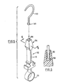
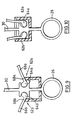
- the embodiment of the improved garment hanger illustrated in Figures 1 to 3 inclusive includes a central support formation 10 and an opposed pair of garment engaging arm formations 12a, 12b interconnected as at 14a, 14b respectively, by hinge-like structures.
- the hinge-like interconnections 14a, 14b provide for swinging movement from an upper limit position 16 as illustrated in broken outline in Figure 2 to a lower limit position 18 as illustrated in figure 3.
- Central support formation 10 includes an upstanding principal element or member 22 terminating uppermost in a suspending hook formation 24 and lowermost in a depending ring-like extension 26 lying generally in the plane of the arm formations 12a, 12b.
- Principal member 22 in the lower region thereof next above the ring-like extension 26 and in spaced relation thereto presents opposed part cylindrical mirror image recesses 28a, 28b, each constituting one part of the hinge-like interconnections 14a, 14b and compare to a hinge barrel.
- the opposed part cylindrical recesses 28a, 28b are open at their ends and along their upper outer quadrants so as to define an appropriate separation or passageway as at 32a, 32b therealong respectively opening outwardly as indicated which constitute sockets 30a, 30b.
- the opposed pair of garment engaging arm formations 12a, 12b which present opposed pintle-like elements 34a, 34b lowermost each having a part cylindrical configuration corresponding to the part cylindrically shaped sockets 30a and 30b, respectively, and appropriately dimensioned for the required registration and rotary movement therewithin.
- gaps 32a, 32b are suitably dimensioned for the registration therewithin of segments 36a, 36b of the opposed arm formations 12a, 12b next above pintle-like components 34a, 34b with the degree of separation of the edges of gaps 32a, 32b determining the extent of swinging movement of arm formations 12a, 12b between the collapsed upper limit position 16 and upon release their descent to the lower garment engaging limit position 18.
- pintle-like elements 34a, 34b could be mounted on the central support formation 10 and the barrel-like sockets 30a, 30b presented by the lower ends of arm formations 12a, 12b respectively so as to constitute the requisite connections.
- Displaceable cup shaped stabilizing member 20 in the preferred embodiment closely embraces interconnections 14a, 14b as illustrated in figures 2 and 3 and includes lower wall 38 suitably slotted as at 40 and upstanding surrounding uniformly spaced-apart side walls 42a, 42b and end walls 44a, 44b.
- Slot 40 is dimensioned for sliding engagement upon central support formation 10 between ring-like extension 26 and interconnections 14a, 14b.
- End walls 44a, 44b of displaceable member 20 have an appropriate upward extent in the lowermost position illustrated in Figure 3 so as to closely flank the opposed ends of pintle-like elements 34a, 34b and thereby serve to maintain their registration with sockets 30a, 30b.
- each pintle-like element 34a, 34b within the sockets 30a, 30b can be maintained with alternative fittings, for example by providing each pintle-like element with an extension on either end, each to be provided with a suitable retaining cap of a diameter exceeding the diameter of the pintle-like element and sockets and contoured to be either snap-fitted thereover or otherwise secured thereto by fasteners, adhesives or the like.
- alternative fittings are known to.persons skilled in the art.
- Displaceable cup shaped member 20 as depicted in Figure 3 is seated upon ring-like extension 26.
- the side walls 42a and 42b have an upward extent such that they engage segments 36a, 36b of opposed arm formations 12a, 12b in fully outwardly extended cantilevered support from the central support formation 10, establishing the lower limit position 18. With this arrangement reinforcing of the connections and additional strengthening of the structure are provided.
- the upper surfaces of side walls 42a, 42b of displaceable member 20, as illustrated in Figure 2, can be suitably shaped so as to smoothly slidingly engage the under surfaces of opposed arm formations 12a, 12b as displaceable member 20 is moved upwardly to swing them toward the upper limit position 16 and to flank the central support formation 10.
- arm formations 12a, 12b will have a slightly upwardly arched or curvate configuration terminating at their outer ends in either a smoothly rolled tip 46 or an enlarged smoothly curvate tip 48.
- the garment hanger illustrated in the exploded view of figure 4 corresponds essentially to the structure of figures 1 to 3, inclusive, and the components thereof that correspond have been designated with the same numerals.
- modified arm formations 50a, 50b are substituted wherein the upper garment engaging segments 52a, 52b likewise having a slight curvature upwardly are reinforced by centrally located depending ribs 54a, 54b preferably dimensioned so that the inner ends will bear against side walls 42a, 42b of displaceable member 20 when disposed in the lower limit position 18.
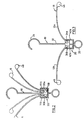
- central support formation 10 1 is provided with an opposed pair of elongated arm formations 12 1 a, 12 1 b interconnected by hinge-like structures as at 14 1 a, 14 1 b, respectively.
- Hinge-like interconnections 14 1 a, 14 1 b provide for displacement or swinging movement from an upper limit position 16 1 as illustrated in Figure 16 to a lower limit position 18 1 as illustrated in Figure 11.
- Central support formation 10 1 includes upstanding principal element or member 22 1 , terminating uppermost in a suspending hook formation 24 1 and lowermost in a depending ring-like extension 26 1 lying generally in the plane of arm formations 12 1 a, 12 1 b.
- Central support formation 10 1 in this embodiment is derived from opposed mating sections 80a, 80b, as detailed in Figure 14 which are of opposite symmetry except for the provision of mating projections 82 and cooperating recesses 84, presented respectively by the opposed surfaces of the sections 80a, 80b.
- the mating projections 82 and cooperating recesses 84 align as well as join the opposed sections 80a, 80b when pressed together to establish a snap fit accompanied by electronic welding of the seams of the joined sections, if desired, when moulded from a suitable plastic.
- Each section 80a, 80b includes opposed contoured recesses 86a, 88a and 86b, 88b respectively lowermost.
- the intervening wall portions as at 98, 100 extend in a generally horizontal direction which in relation to the part-cylindrical receptacle portions 90, 92 can be characterized as part chord-like.
- the wall portions 98, 100 cooperate with upper surfaces, 102, 104 of the inner ends of opposed arm formations 12 1 a, 12 1 b respectively to limit displacement downwardly as appears from the broken outline in Figure 11.
- Each section, 80a, 80b is provided with a pair of apertures 106a, 108a, 106b, 108b, respectively, centrally of contoured recesses 86a, 86b, 88a, 88b respectively, which are so shaped as to mate in rotating fit with opposed pintle-like projections 110, 112 and 114, 116 presented by respective inner ends of arm formations 12 1 a, 12 1 b.
- Arm formations 12 1 a, 12 1 b are preferably generally channel-shaped as revealed by Figure 14. Such channel-shaped configuration ensures substantial resistance to deformation under reasonable loading from above.
- channel-shaped formations 12 1 a, 12 1 b preferably have a part-circular configuration as illustrated in broken outline in Figure 11 as at 128a, 128b respectively and in solid outline in Figure 14 to match the shaping of the part-cylindrical hollow receptacle portions 90, 92 for partial rotary displacement therewithin.
- the upper surfaces 102, 104 of arm formations 12 1 a, 12 1 b in the region of the inner ends thereof are adapted to fully engage chord-like wall portions 98, 100 of hollow receptacle portions 90, 92 with arm formations 12 1 a, 12 1 b extending outwardly in cantilever fashion for supporting the garment as illustrated in Figure 11.
- the elongated arm formations 12 1 a, 12 1 b are also smoothly contoured and have a slight upwardly curvate configuration terminating outermost in smoothly rounded depending ends as depicted in Figure 11.
- the arm formations 12 1 a, 12 1 b are connected to the lower region of central support formation 10 1 in next adjacent relation so as to minimize the lateral extent of the lower region of the support formation to which the arm formations are attached.
- arm formations 12 1 a, 12 1 b are seen to lie in a common plane with the plane of central support formation 10 1 as revealed by figures 12 and 14.
- peripheral configuration of the lower region of central support formation 10 1 is appropriately rounded as at 130 in Figures 11 and 16 as is the depending ring extension 26 1 as at 132.
- the garment hanger takes on a streamlined or arrowhead-like configuration so as to easily pass through the neck opening of a garment.
- arm formations 12 1 a, 12 1 b when entered within the garment it will be understood that upon their release from confinement they commence to smoothly engage with the inner shoulder regions thereof and descend therewith to the lower limit garment-supporting disposition.
- the principal components of the garment hangers be moulded from a suitable plastic possessing sufficient inherent resistance to deformation and deterioration under loading and climatic conditions.
- displaceable stabilizing member 20 presents a plane of symmetry and therefore can be constructed from two identical parts produced from a single mould.
- the arm formations 12a, 12b or alternative arm formations 50a, 50b are assembled together in the manner illustrated by the aligned centre lines of the respective sockets and pintles in the exploded views of Figures 1 and 4 by registering the pintle-like elements 34a, 34b within sockets 30a, 30b through their open ends with the segments 36a, 36b aligned with the gaps 32a, 32b.
- This step is followed by the registration of the opposed parts of displaceable cup shaped member 20 in position below the hinge-like interconnections 14a, 14b and above the extension 26 and appropriately sealing them or welding them together to confine the pintle-like elements 34a, 34b within sockets 30a, 30b and serve the other purposes already outlined.
- sections 80a, 80b constituting central support formation 10 1 as represented in Figures 14 and 15 and arm formations 12 1 a, 12 1 b are arranged in alignment as indicated by the broken centre lines 134 and 136 in Figure 14 whereby sections 80a, 80b can then be press-fitted together to bring projections 82 into engagement with matching recesses 84 and against separation as in a snap fit.
- pintles 110, 112 and 114, 116 brought into registration within the opposed matching openings 106a, 106b and 108a, 108b of the respective sections 80a, 80b whereby the inner ends of arm formation 12 1 a, 12 1 b are captured for partial rotation or displacement and whereby with that step a fully operative garment hanger embodying the invention produced.
- the improved garment hangers so constructed are intended to be utilized in the following manner.
- the garment hangers when collapsed assume a planar disposition. With the arm formations 12a, 12b, 50a, 50b or 12 1 a, 12 1 b so held in or confined to the upper limit positions 16, 16 1 respectively the garment hanger is oriented for introduction of same through the neck opening until the arm formations pass therethrough.
- the hanger can be removed through the waist opening by grasping the depending ring-like extension and drawing the central support formation and associated arm formations towards the waist opening which causes collapse of the garment hanger as earlier outlined which facilitates withdrawal from below.
- collapsible garment hanger can manipulation and/or handling of garment to be hung or removed therefrom be significantly lessened and any soiling or other risk of damage reduced.
- central support formation 52 is provided with an enlarged section uppermost recessed as at 56 to provide a vertical channel open at the top and terminating lowermost in an enlarged cavity.
- the enlarged cavity is shaped so as to receive an enlarged suitably shaped lower end or foot 58 of a modified hook formation 60 in rotary fit.
- the hook formation 60 is swivelly mounted within section 54 to provide for ease in mounting the improved garment hanger in a closet, in a display structure or otherwise.
- alternative interconnection 62a, 62b can be utilized in which a part ovate or part elliptical configuration is applied to the pintle-like elements 64a, 64b for registration within the part-cylindrical open-ended sockets 30a, 30b the major axis of the part elliptically-shaped pintle-like elements corresponding to the diameter of the part cylindrically-shaped sockets.
- the arm formations 66a, 66b are offset from the foci -of the part elliptically-shaped pintle-like elements 64a, 64b and extend generally tangentially in relation to the major axis, as illustrated, so that segments 68a, 68b in the lower limit position can be brought into full aligned registration with the opposed contoured upper edges of the displaceable element 20 as illustrated in Figure 9.
- the upper edges 67a, 67b of the gaps 32a, 32b can either be turned down more sharply or extended if desired to better confine the part elliptically-shaped pintle-like elements 64a, 64b as well as to further limit the upward swinging movement of the arm formations 66a, 66b.
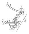
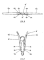
- hanger is shown turned up-side-down with the ring-like extension 26 disposed uppermost and engaged over a projecting rod-like segment 70 presented by a novel storage hanger device 72 which in turn is to be suspended from a suitable support, preferably by means of an integral hook formation 73.
- Rod-like segment 70 and supporting segment 74 of storage hanger device 72 preferably have a generally linear extent and present a contained angle of the order of 20 degrees at their intersection, with the intersection offset from the point of suspension as illustrated in Figure 8 whereby rod-like segment 70 will be supported to angle slightly upwardly.
- hanger device 72 With hanger device 72 itself suspended the first and subsequent garment hangers so engaged over rod-like segment 70 by means of their ring-like extensions 26 will descend in sequence therealong towards the intersection of segments 70, 74. This applied load swings suspended hanger device 72 in a direction to maintain the load in balance yet will continue to present rod-like segment 70 upwardly at an angle to the horizontal so as to preserve the interengagement.
- storage device 72 facilitate effective storage for the improved garment hangers but also provides for ready access to them when the storage hanger device 72 is hung in a closet or at a work station in a commercial establishment or otherwise.
Landscapes
- Holders For Apparel And Elements Relating To Apparel (AREA)
Claims (11)
- Porte-vêtement comprenant une formation de support central vertical (10, 10') comprenant des moyens permettant de suspendre celui-ci depuis sa région supérieure (24, 24') de façon à dépendre d'une façon généralement verticale depuis celui-ci et présentant des régions latérales opposées, une paire opposée de formations de bras allongés aux contours généralement lisses (12a, 12b) (12'a, 12'b) présentant des extrémités interne et externe respectivement comportant des moyens opposés (14a, 14b) (14'a, 14'b) reliant chacune desdites extrémités internes à la région inférieure de ladite formation de support central selon une relation espacée de façon à s'étendre vers l'extérieur des dites régions latérales et à leur permettre d'osciller dans un plan commun depuis une disposition supérieure rabattue encadrant ladite formation de support central vers une disposition inférieure s'étendant vers l'extérieur de support du vêtement, caractérisé en ce que lesdits moyens de connexion opposés (14a, 14b) (14'a, 14'b) comprennent une paire de moyens à douille (28a, 28b) (90, 92, 94, 96) s'ouvrant chacun à l'opposé vers l'extérieur et vers le haut par rapport à une région latérale respective de la formation de support central, l'extrémité interne de chaque formation de bras respective étant disposée à l'intérieur, et des moyens de type pivot (34a, 34b) (110, 112) (114, 116) retenant l'extrémité interne de chacune desdites formations de bras au sein desdits moyens à douille respectifs (28a, 28b), (90, 92, 94, 96), et étant façonnés de façon à orienter et confiner ladite formation de bras pour qu'elle oscille dans ledit plan commun et chacun desdits moyens à douille présentant une configuration qui permet de définir un passage (32a, 32b) (86a, 86b), (88a, 88b) destiné à la réception de l'extrémité interne de chaque formation de bras respective et de la région placée juste au-dessus desdits moyens de pivot, ledit passage étant suffisant pour que ladite formation de bras oscille depuis ladite disposition supérieure rabattue vers ladite disposition inférieure de support du vêtement.
- Porte-vêtement selon la revendication 1, dans lequel ladite formation de support central (10') se compose de composants opposés symétriquement par rapport à un miroir (80a, 80b) joints ensemble, et dans lequel lesdits moyens à douille opposés (90, 92) (94, 96) sont présentés par lesdits composants de façon à s'étendre entre les deux et lesdits moyens de pivot (110, 112) (114, 116) sont présentés par chacune desdites extrémités inférieures respectives desdites formations de bras (12'a, 12'b) vers chacun desdits moyens à douille opposés respectifs (90, 92) (94, 96), lesdits composants joints ainsi ensemble retenant lesdites formations de bras (12'a) (12'b) à l'intérieur en leur évitant une séparation.
- Porte-vêtement selon la revendication 1, dans lequel un moyen mobile (20) est supporté par ladite formation de support central (10) au-dessous des dits moyens de connexion (14a, 14b), ledit moyen mobile (20) présentant une configuration et une extension vers le haut par déplacement permettant d'engager lesdites formations de bras opposées (12a, 12b) depuis le dessous et de faire osciller celles-ci depuis la disposition inférieure de support de vêtement vers le haut vers ladite disposition supérieure rabattue.
- Porte-vêtement selon la revendication 3, dans lequel ledit moyen mobile (20) présente une configuration en forme de coupelle ouverte vers le haut, ladite formation de support central (10) présentant un moyen d'arrêt (26) en dessous pour limiter sa descente vers le bas de façon telle qu'en position la plus basse, l'étendue vers le haut dudit moyen mobile en forme de coupelle (20) encadre intimement lesdits moyens de connexion (14a, 14b) et engage totalement les extrémités internes desdites formations de bras (12a, 12b) adjacentes auxdits moyens de connexion depuis le dessous lorsqu'elles sont disposées dans la position inférieure de support de vêtement de celles-ci.
- Porte-vêtement selon la revendication 1, dans lequel lesdites paires opposées de formations de bras (12a, 12b) (12'a, 12'b) présentent chacune une configuration incurvée vers le haut et se terminent à leur extrémité externe en formations à bout arrondi lisse.
- Porte-vêtement selon la revendication 1, dans lequel lesdites paires opposées de formations de bras comportent une section transversale supérieure présentant une section à nervure de renforcement intégrale dépendante sous celles-ci et s'étendant le long de celles-ci.
- Porte-vêtement selon la revendication 1, dans lequel lesdites paires opposées de formations de bras présentent chacune une configuration généralement en forme de canal dont le côté ouvert s'ouvre vers le bas.
- Porte-vêtement selon la revendication 1, dans lequel ladite formation de support central présente une extension dépendante au niveau le plus bas disposée généralement dans le plan desdites formations de bras pour orienter celles-ci de façon à pénétrer dans l'ouverture d'encolure d'un vêtement et à l'en retirer.
- Porte-vêtement selon la revendication 1, dans lequel chacun desdits moyens de type pivot (34a, 34b) (110, 112) (114, 116) présente une configuration en partie cylindrique qui correspond auxdits moyens à douille respectifs (28a, 28b) (90, 92, 94, 96), lesdites formations de bras respectives (12a, 12b) (12'a, 12'b) s'étendant généralement diamétralement vers l'extérieur depuis ceux-ci.
- Porte-vêtement selon la revendication 1, dans lequel chacun desdits moyens de type pivot (64a, 64b) présente une configuration en partie elliptique dont l'axe principal correspond au diamètre de ladite configuration en partie cylindrique desdits moyens à douille respectifs (30a, 30b), chacune desdites formations de bras respectives (66a, 66b) s'étendant vers l'extérieur depuis lesdits moyens de type pivot (64a, 64b) selon une relation substantiellement tangentielle par rapport audit axe principal.
- Porte-vêtement selon la revendication 1, dans lequel ladite formation de support central (52) comprend un élément à crochet de suspension (60) dans la partie supérieure, ledit élément à crochet (60) présentant une formation de pied dépendante (58) et un moyen (56) présenté par ladite formation de support central (52) qui enferme ladite formation de pied dépendante pour un soutien pivotant de celle-ci, ladite formation de support central étant reliée à celle-ci de façon à pivoter.
Applications Claiming Priority (5)
| Application Number | Priority Date | Filing Date | Title |
|---|---|---|---|
| US46367295A | 1995-06-05 | 1995-06-05 | |
| US463672 | 1995-06-05 | ||
| US08/610,929 US5810216A (en) | 1995-06-05 | 1996-03-05 | Garment hanger and storage device therefore |
| US610929 | 1996-03-05 | ||
| PCT/CA1996/000411 WO1996039069A1 (fr) | 1995-06-05 | 1996-06-04 | Porte-vetement et son dispositif de stockage |
Publications (2)
| Publication Number | Publication Date |
|---|---|
| EP0957738A1 EP0957738A1 (fr) | 1999-11-24 |
| EP0957738B1 true EP0957738B1 (fr) | 2003-04-16 |
Family
ID=27040714
Family Applications (1)
| Application Number | Title | Priority Date | Filing Date |
|---|---|---|---|
| EP96918555A Expired - Lifetime EP0957738B1 (fr) | 1995-06-05 | 1996-06-04 | Porte-vetement et son dispositif de stockage |
Country Status (4)
| Country | Link |
|---|---|
| EP (1) | EP0957738B1 (fr) |
| AU (1) | AU6118996A (fr) |
| DE (1) | DE69627543D1 (fr) |
| WO (1) | WO1996039069A1 (fr) |
Families Citing this family (2)
| Publication number | Priority date | Publication date | Assignee | Title |
|---|---|---|---|---|
| US5901888A (en) * | 1998-06-05 | 1999-05-11 | Brainy Ideas, Inc. | Device, method, and system for clothing organization |
| DE29901451U1 (de) | 1999-01-28 | 1999-05-20 | Coronet-Metallwarenfabrik GmbH, 69483 Wald-Michelbach | Kleiderbügel |
Family Cites Families (7)
| Publication number | Priority date | Publication date | Assignee | Title |
|---|---|---|---|---|
| GB320000A (en) * | 1929-01-02 | 1929-10-03 | Frank Evelyn Vickers | Improved construction of trouser hanger |
| GB328828A (en) * | 1929-05-27 | 1930-05-08 | George Frederic Mcgill | Improvements in telescoping and folding garment hanger |
| GB354526A (en) * | 1930-07-22 | 1931-08-13 | Harold Frederick Heath | Improvements in garment hangers |
| GB759905A (en) * | 1953-05-19 | 1956-10-24 | Crayonne Ltd | Improvements in or relating to coat hangers |
| FR1342005A (fr) * | 1962-04-24 | 1963-11-02 | Algemene Transport En Expediti | Méthode de transport de pièces de vêtements et dispositif de suspension pour l'application de cette méthode |
| US3485423A (en) * | 1968-08-28 | 1969-12-23 | Cluett Peabody & Co Inc | Garment hanger |
| CH649207A5 (en) * | 1980-11-21 | 1985-05-15 | Stoba Ag | Collapsible clothes-hanger |
-
1996
- 1996-06-04 EP EP96918555A patent/EP0957738B1/fr not_active Expired - Lifetime
- 1996-06-04 AU AU61189/96A patent/AU6118996A/en not_active Abandoned
- 1996-06-04 DE DE69627543T patent/DE69627543D1/de not_active Expired - Lifetime
- 1996-06-04 WO PCT/CA1996/000411 patent/WO1996039069A1/fr not_active Ceased
Also Published As
| Publication number | Publication date |
|---|---|
| EP0957738A1 (fr) | 1999-11-24 |
| DE69627543D1 (de) | 2003-05-22 |
| WO1996039069A1 (fr) | 1996-12-12 |
| AU6118996A (en) | 1996-12-24 |
Similar Documents
| Publication | Publication Date | Title |
|---|---|---|
| US6609640B1 (en) | Pinch-grip hanger | |
| US4023762A (en) | Article suspension device | |
| US4759480A (en) | Garment hanger with auxiliary bar | |
| US6409057B1 (en) | Garment hanger with size window | |
| US5810216A (en) | Garment hanger and storage device therefore | |
| US8910837B2 (en) | Sliding-carriage garment hanger | |
| US5649652A (en) | Clothes hanger with storage hook | |
| CA1116578A (fr) | Suspension pivotable | |
| US3792804A (en) | Garment hanger | |
| US5992713A (en) | Clothes hanger with slidable side attachments | |
| US6308872B1 (en) | Hanger with multiple means for supporting other hangers | |
| US4177908A (en) | Locking parallel bar hanger | |
| US4750697A (en) | Hook for coat-hangers, equipped with a double-jointed supporting base | |
| US5934524A (en) | Multiple purpose garment and accessory rack | |
| JP2000506763A (ja) | 調節自在な支持棒を備えた衣服セットハンガー | |
| EP0957738B1 (fr) | Porte-vetement et son dispositif de stockage | |
| US3741449A (en) | Garment hanger | |
| CN1138498C (zh) | 可折叠挂衣服的衣架 | |
| EP0302755B1 (fr) | Présentoir | |
| US20020038788A1 (en) | Clothes hanger organization method and system | |
| US6244478B1 (en) | Clothes hanger | |
| CN221229151U (zh) | 一种子母式挂衣架 | |
| CN216602412U (zh) | 一种折叠衣架 | |
| KR200287318Y1 (ko) | 정장바지용 옷걸이 | |
| GB2350058A (en) | Multiple clothes hanger assembly |
Legal Events
| Date | Code | Title | Description |
|---|---|---|---|
| PUAI | Public reference made under article 153(3) epc to a published international application that has entered the european phase |
Free format text: ORIGINAL CODE: 0009012 |
|
| 17P | Request for examination filed |
Effective date: 19980105 |
|
| AK | Designated contracting states |
Kind code of ref document: A1 Designated state(s): BE DE FR GB IT NL SE |
|
| 17Q | First examination report despatched |
Effective date: 20010209 |
|
| GRAG | Despatch of communication of intention to grant |
Free format text: ORIGINAL CODE: EPIDOS AGRA |
|
| GRAG | Despatch of communication of intention to grant |
Free format text: ORIGINAL CODE: EPIDOS AGRA |
|
| GRAG | Despatch of communication of intention to grant |
Free format text: ORIGINAL CODE: EPIDOS AGRA |
|
| GRAH | Despatch of communication of intention to grant a patent |
Free format text: ORIGINAL CODE: EPIDOS IGRA |
|
| GRAH | Despatch of communication of intention to grant a patent |
Free format text: ORIGINAL CODE: EPIDOS IGRA |
|
| GRAA | (expected) grant |
Free format text: ORIGINAL CODE: 0009210 |
|
| AK | Designated contracting states |
Designated state(s): BE DE FR GB IT NL SE |
|
| PG25 | Lapsed in a contracting state [announced via postgrant information from national office to epo] |
Ref country code: NL Free format text: LAPSE BECAUSE OF FAILURE TO SUBMIT A TRANSLATION OF THE DESCRIPTION OR TO PAY THE FEE WITHIN THE PRESCRIBED TIME-LIMIT Effective date: 20030416 Ref country code: IT Free format text: LAPSE BECAUSE OF FAILURE TO SUBMIT A TRANSLATION OF THE DESCRIPTION OR TO PAY THE FEE WITHIN THE PRE;WARNING: LAPSES OF ITALIAN PATENTS WITH EFFECTIVE DATE BEFORE 2007 MAY HAVE OCCURRED AT ANY TIME BEFORE 2007. THE CORRECT EFFECTIVE DATE MAY BE DIFFERENT FROM THE ONE RECORDED.SCRIBED TIME-LIMIT Effective date: 20030416 Ref country code: FR Free format text: LAPSE BECAUSE OF FAILURE TO SUBMIT A TRANSLATION OF THE DESCRIPTION OR TO PAY THE FEE WITHIN THE PRESCRIBED TIME-LIMIT Effective date: 20030416 Ref country code: BE Free format text: LAPSE BECAUSE OF FAILURE TO SUBMIT A TRANSLATION OF THE DESCRIPTION OR TO PAY THE FEE WITHIN THE PRESCRIBED TIME-LIMIT Effective date: 20030416 |
|
| REG | Reference to a national code |
Ref country code: GB Ref legal event code: FG4D |
|
| REF | Corresponds to: |
Ref document number: 69627543 Country of ref document: DE Date of ref document: 20030522 Kind code of ref document: P |
|
| PG25 | Lapsed in a contracting state [announced via postgrant information from national office to epo] |
Ref country code: SE Free format text: LAPSE BECAUSE OF FAILURE TO SUBMIT A TRANSLATION OF THE DESCRIPTION OR TO PAY THE FEE WITHIN THE PRESCRIBED TIME-LIMIT Effective date: 20030716 Ref country code: GB Free format text: LAPSE BECAUSE OF NON-PAYMENT OF DUE FEES Effective date: 20030716 |
|
| PG25 | Lapsed in a contracting state [announced via postgrant information from national office to epo] |
Ref country code: DE Free format text: LAPSE BECAUSE OF FAILURE TO SUBMIT A TRANSLATION OF THE DESCRIPTION OR TO PAY THE FEE WITHIN THE PRESCRIBED TIME-LIMIT Effective date: 20030717 |
|
| NLV1 | Nl: lapsed or annulled due to failure to fulfill the requirements of art. 29p and 29m of the patents act | ||
| PLBE | No opposition filed within time limit |
Free format text: ORIGINAL CODE: 0009261 |
|
| STAA | Information on the status of an ep patent application or granted ep patent |
Free format text: STATUS: NO OPPOSITION FILED WITHIN TIME LIMIT |
|
| GBPC | Gb: european patent ceased through non-payment of renewal fee |
Effective date: 20030716 |
|
| 26N | No opposition filed |
Effective date: 20040119 |
|
| EN | Fr: translation not filed |