EP0957774B1 - Dispositif et procede adaptes pour fermer une incision dans un corps soumis a une autopsie - Google Patents
Dispositif et procede adaptes pour fermer une incision dans un corps soumis a une autopsie Download PDFInfo
- Publication number
- EP0957774B1 EP0957774B1 EP96905758A EP96905758A EP0957774B1 EP 0957774 B1 EP0957774 B1 EP 0957774B1 EP 96905758 A EP96905758 A EP 96905758A EP 96905758 A EP96905758 A EP 96905758A EP 0957774 B1 EP0957774 B1 EP 0957774B1
- Authority
- EP
- European Patent Office
- Prior art keywords
- incision
- closing
- sheet
- strap
- trace
- Prior art date
- Legal status (The legal status is an assumption and is not a legal conclusion. Google has not performed a legal analysis and makes no representation as to the accuracy of the status listed.)
- Expired - Lifetime
Links
- 238000011888 autopsy Methods 0.000 title claims abstract description 25
- 238000000034 method Methods 0.000 title claims description 9
- 239000000463 material Substances 0.000 claims abstract description 92
- 239000000853 adhesive Substances 0.000 claims abstract description 45
- 230000001070 adhesive effect Effects 0.000 claims abstract description 45
- 239000011888 foil Substances 0.000 claims description 15
- 238000007373 indentation Methods 0.000 claims description 14
- 239000000416 hydrocolloid Substances 0.000 claims description 7
- 239000010410 layer Substances 0.000 claims description 7
- 239000012790 adhesive layer Substances 0.000 claims description 6
- 229920002635 polyurethane Polymers 0.000 claims description 5
- 239000004814 polyurethane Substances 0.000 claims description 5
- DQXBYHZEEUGOBF-UHFFFAOYSA-N but-3-enoic acid;ethene Chemical compound C=C.OC(=O)CC=C DQXBYHZEEUGOBF-UHFFFAOYSA-N 0.000 claims description 4
- 239000005038 ethylene vinyl acetate Substances 0.000 claims description 4
- 229920001200 poly(ethylene-vinyl acetate) Polymers 0.000 claims description 4
- 239000004709 Chlorinated polyethylene Substances 0.000 claims description 2
- 229920012485 Plasticized Polyvinyl chloride Polymers 0.000 claims description 2
- XTXRWKRVRITETP-UHFFFAOYSA-N Vinyl acetate Chemical compound CC(=O)OC=C XTXRWKRVRITETP-UHFFFAOYSA-N 0.000 claims description 2
- 239000002390 adhesive tape Substances 0.000 claims description 2
- -1 polypropylene Polymers 0.000 description 5
- PPBRXRYQALVLMV-UHFFFAOYSA-N Styrene Chemical compound C=CC1=CC=CC=C1 PPBRXRYQALVLMV-UHFFFAOYSA-N 0.000 description 4
- 241000826860 Trapezium Species 0.000 description 4
- 238000004519 manufacturing process Methods 0.000 description 4
- 238000007789 sealing Methods 0.000 description 4
- 239000004698 Polyethylene Substances 0.000 description 3
- 230000006978 adaptation Effects 0.000 description 3
- 229920001971 elastomer Polymers 0.000 description 3
- 239000000806 elastomer Substances 0.000 description 3
- 230000007246 mechanism Effects 0.000 description 3
- 229920000573 polyethylene Polymers 0.000 description 3
- GRWFGVWFFZKLTI-IUCAKERBSA-N (-)-α-pinene Chemical compound CC1=CC[C@@H]2C(C)(C)[C@H]1C2 GRWFGVWFFZKLTI-IUCAKERBSA-N 0.000 description 2
- 239000004677 Nylon Substances 0.000 description 2
- 239000004743 Polypropylene Substances 0.000 description 2
- 238000010521 absorption reaction Methods 0.000 description 2
- 210000001124 body fluid Anatomy 0.000 description 2
- ZSWFCLXCOIISFI-UHFFFAOYSA-N cyclopentadiene Chemical compound C1C=CC=C1 ZSWFCLXCOIISFI-UHFFFAOYSA-N 0.000 description 2
- 208000015181 infectious disease Diseases 0.000 description 2
- 238000001746 injection moulding Methods 0.000 description 2
- 238000005304 joining Methods 0.000 description 2
- 229920001778 nylon Polymers 0.000 description 2
- 229920001155 polypropylene Polymers 0.000 description 2
- 238000001356 surgical procedure Methods 0.000 description 2
- WTARULDDTDQWMU-RKDXNWHRSA-N (+)-β-pinene Chemical compound C1[C@H]2C(C)(C)[C@@H]1CCC2=C WTARULDDTDQWMU-RKDXNWHRSA-N 0.000 description 1
- WTARULDDTDQWMU-IUCAKERBSA-N (-)-Nopinene Natural products C1[C@@H]2C(C)(C)[C@H]1CCC2=C WTARULDDTDQWMU-IUCAKERBSA-N 0.000 description 1
- HECLRDQVFMWTQS-RGOKHQFPSA-N 1755-01-7 Chemical compound C1[C@H]2[C@@H]3CC=C[C@@H]3[C@@H]1C=C2 HECLRDQVFMWTQS-RGOKHQFPSA-N 0.000 description 1
- NIXOWILDQLNWCW-UHFFFAOYSA-M Acrylate Chemical compound [O-]C(=O)C=C NIXOWILDQLNWCW-UHFFFAOYSA-M 0.000 description 1
- 239000004215 Carbon black (E152) Substances 0.000 description 1
- 206010013786 Dry skin Diseases 0.000 description 1
- IAYPIBMASNFSPL-UHFFFAOYSA-N Ethylene oxide Chemical compound C1CO1 IAYPIBMASNFSPL-UHFFFAOYSA-N 0.000 description 1
- 239000004606 Fillers/Extenders Substances 0.000 description 1
- WTARULDDTDQWMU-UHFFFAOYSA-N Pseudopinene Natural products C1C2C(C)(C)C1CCC2=C WTARULDDTDQWMU-UHFFFAOYSA-N 0.000 description 1
- 238000004026 adhesive bonding Methods 0.000 description 1
- XCPQUQHBVVXMRQ-UHFFFAOYSA-N alpha-Fenchene Natural products C1CC2C(=C)CC1C2(C)C XCPQUQHBVVXMRQ-UHFFFAOYSA-N 0.000 description 1
- MVNCAPSFBDBCGF-UHFFFAOYSA-N alpha-pinene Natural products CC1=CCC23C1CC2C3(C)C MVNCAPSFBDBCGF-UHFFFAOYSA-N 0.000 description 1
- 239000003963 antioxidant agent Substances 0.000 description 1
- 230000003078 antioxidant effect Effects 0.000 description 1
- 238000005452 bending Methods 0.000 description 1
- 229930006722 beta-pinene Natural products 0.000 description 1
- 238000009833 condensation Methods 0.000 description 1
- 230000005494 condensation Effects 0.000 description 1
- 238000010276 construction Methods 0.000 description 1
- 229920001577 copolymer Polymers 0.000 description 1
- 238000005520 cutting process Methods 0.000 description 1
- 230000032798 delamination Effects 0.000 description 1
- 230000037336 dry skin Effects 0.000 description 1
- 230000000694 effects Effects 0.000 description 1
- 239000012530 fluid Substances 0.000 description 1
- LCWMKIHBLJLORW-UHFFFAOYSA-N gamma-carene Natural products C1CC(=C)CC2C(C)(C)C21 LCWMKIHBLJLORW-UHFFFAOYSA-N 0.000 description 1
- 230000009477 glass transition Effects 0.000 description 1
- 229930195733 hydrocarbon Natural products 0.000 description 1
- 150000002430 hydrocarbons Chemical class 0.000 description 1
- 239000002480 mineral oil Substances 0.000 description 1
- 238000012986 modification Methods 0.000 description 1
- 230000004048 modification Effects 0.000 description 1
- 239000003921 oil Substances 0.000 description 1
- 230000000149 penetrating effect Effects 0.000 description 1
- 239000004014 plasticizer Substances 0.000 description 1
- 229920000642 polymer Polymers 0.000 description 1
- 239000000843 powder Substances 0.000 description 1
- 238000003825 pressing Methods 0.000 description 1
- 238000004080 punching Methods 0.000 description 1
- GRWFGVWFFZKLTI-UHFFFAOYSA-N rac-alpha-Pinene Natural products CC1=CCC2C(C)(C)C1C2 GRWFGVWFFZKLTI-UHFFFAOYSA-N 0.000 description 1
- 230000005855 radiation Effects 0.000 description 1
- 229920005989 resin Polymers 0.000 description 1
- 239000011347 resin Substances 0.000 description 1
- 238000000926 separation method Methods 0.000 description 1
- 230000001954 sterilising effect Effects 0.000 description 1
- 238000004659 sterilization and disinfection Methods 0.000 description 1
- 229920006132 styrene block copolymer Polymers 0.000 description 1
- 238000007920 subcutaneous administration Methods 0.000 description 1
- 239000012815 thermoplastic material Substances 0.000 description 1
- 230000007704 transition Effects 0.000 description 1
- XLYOFNOQVPJJNP-UHFFFAOYSA-N water Substances O XLYOFNOQVPJJNP-UHFFFAOYSA-N 0.000 description 1
- 230000003313 weakening effect Effects 0.000 description 1
- 238000003466 welding Methods 0.000 description 1
Images


Classifications
-
- A—HUMAN NECESSITIES
- A61—MEDICAL OR VETERINARY SCIENCE; HYGIENE
- A61B—DIAGNOSIS; SURGERY; IDENTIFICATION
- A61B16/00—Devices specially adapted for vivisection or autopsy
-
- A—HUMAN NECESSITIES
- A61—MEDICAL OR VETERINARY SCIENCE; HYGIENE
- A61B—DIAGNOSIS; SURGERY; IDENTIFICATION
- A61B17/00—Surgical instruments, devices or methods
- A61B17/08—Wound clamps or clips, i.e. not or only partly penetrating the tissue ; Devices for bringing together the edges of a wound
-
- A—HUMAN NECESSITIES
- A61—MEDICAL OR VETERINARY SCIENCE; HYGIENE
- A61B—DIAGNOSIS; SURGERY; IDENTIFICATION
- A61B17/00—Surgical instruments, devices or methods
- A61B17/12—Surgical instruments, devices or methods for ligaturing or otherwise compressing tubular parts of the body, e.g. blood vessels or umbilical cord
- A61B17/132—Tourniquets
- A61B17/1322—Tourniquets comprising a flexible encircling member
- A61B17/1327—Tensioning clamps
Definitions
- the present invention relates to a device suitable for use in closing an incision in a body in connection with autopsy, in particular a longitudinal incision along the centre line of the body, which device comprises at least one flexible sheet of material with a surface intended for facing the body and an opposite surface intended for facing away from the body, the body facing surface being provided with an adhesive, by means of which the device may be adhesively attached to the body in such a way that the device is present on both sides of the incision trace, and which device comprises two rows of mutually cooperating means for use in closing the incision, said rows of closing means being present on each side of the incision trace and allowing the incision to be made after adhesive attachment of the device, and a method for closing an incision in a body in connection with autopsy by use of such a device.
- Both staples and suture needles suffer from the drawback that they cause an additional damage of the tissue surrounding the incision and entail the risk of the needle or the staple penetrating the operation glove and damaging the operator's own tissue with resultant risk of infection, for instance by HIV. This is particularly a potential risk in connection with autopsy.
- the device may be used in connection with autopsy
- the patent is, however, directed to a device for closing superficial incisions (skin separations), and it is specifically mentioned in the patent that subcutaneous suturing may be required in case of deep incisions.
- the problem is not only due to the fact that the body generally is curved in this area, but also that there are big differences from person to person as to the shape of the neck and clavicular area.
- the invention thus relates to a device suited for use in closing an incision in a body in connection with autopsy, in particular a longitudinal incision along the centre line of the body, which device comprises at least one flexible sheet of material with a surface intended for facing the body and an opposite surface facing away from the body, the body facing surface being provided with an adhesive, by means of which the device may be adhesively attached to the body in such a way that the device is present on both sides of the incision trace, and which device comprises two rows of mutually cooperating means for use in closing the incision, said rows of closing means being present on each side of the incision trace and allowing the incision to be made after adhesive attachment of the device, which device is characterized in that said at least one sheet of material comprises a portion intended for being adhesively attached to the neck area of the body, which neck portion comprises an outwardly extending flap portion on each side of a line corresponding to the centre line of the body, and in that said at least one sheet of material at the end facing the neck portion comprises a portion, the side lines of which
- the outwardly directed flaps give in combination with the constricted part a configuration which enables the adaptation of the device to the contour of neck and clavicular areas of varying shape. At the same time the outwardly directed flaps give an increased surface which contributes to a better fixing of the device in the area in question, which is of vital importance, as the skin in this area is very movable, and as in particular this area is subjected to considerable forces during an autopsy.
- the flap portions extend obliquely outwardly and upwardly seen relative to a line corresponding to the centre line of the body and relative to the orientation of the body in upright position, respectively.
- the outwardly extending flap portions have such a length that together with the intermediate part of the neck portion they span a distance of at least 25 cm, preferably at least 35 cm and particularly a distance of 40 - 55 cm.
- the flaps may be able to reach each other in the back of the neck and even overlap somewhat, which gives a further safe securing of the device.
- the ratio between the distance, which the outwardly extending flap portions and the intermediate part of the neck portion span, and the width of the portion with the substantially converging side lines, at the place, where the distance between them is smallest, will in most cases be about 1.5 or more.
- the neck portion is designed as a separate unit. This makes a better utilization of the material possible, just as an additional possibility of adjustment is provided, the neck portion being thereby displaceable relative to the portion with the converging side lines.
- the neck portion is substantially trapezoidal, for instance designed as a trapezium where the distance between the parallel sides is of the magnitude 2 - 4 cm, and the corners at the base line of the trapezium are cut off, such that the neck portion in each side ends in a flap with a width of the magnitude 1 - 2 cm.
- the edges do not have to be completely straight.
- one of the parallel sides may be slightly convex and the other slightly concave, just as only one of these sides may be slightly convex or slightly concave.
- Such a substantially trapezoidal, separately formed neck portion may depending on the shape of the neck and clavicular area be adhesively attached either with the short side upwards or with the short side downwards. Normally, it will, however, be designed with a view to being adhesively attached with the short side upwards.
- the neck portion c is therefore provided with two rows of mutually cooperating closing means 7, 8, which extend into the outwardly directed flap portions 19, 20 for use in closing such an incision.
- the device according to the invention It is preferred to completely or partially design the device according to the invention with rounded corners to reduce the risk of detachment during handling of the body. This especially applies to the corners of the neck portion.
- the portion with converging side lines is provided with notches or indentations in the edges running along these side lines in order to further improve the adjustment possibilities.
- These notches or indentations are preferably formed by removal of a part of the sheet of material, as there would otherwise be a risk of rejoining by cold flowing of the adhesive and of overlapping, when the release paper or foil is removed for adhesive attachment of the device.
- the neck portion may be provided with a recess for receiving the curvature of a neck.
- said sheet of material comprises in general a substantially rectangular oblong portion, in which a part of the two rows of mutually cooperating means for use in closing the incision is present, said the means being positioned such that the two rows of means are present on either side of the intended incision trace and allow the incision to be made after adhesive attachment of the device.
- the closing means cooperate in pairs, one means positioned on one side of the incision trace cooperating with a means positioned oppositely on the other side of the incision trace, and the two means of a pair, independently of the remaining pairs of cooperating means, may be connected operatively for closing the incision. This makes a stepwise closing of the incision possible.
- the closing means of a pair are provided with means for releasable locking of the closing means relative to each other during the closing operation. This makes it possible to carry out a gradual, controlled closing of the incision by alternating manipulation of the pairwise cooperating closing means, until the incision has been closed all over its length.
- the ratio between the width of the rectangular portion and the width of the portion with the substantially converging side lines at the place, where the distance between them is smallest, will in most cases be about 1.2 or more, preferably about 1.5 or more and in particular 1.5 to 2.5.
- one closing means of a pair comprises a strap-like element
- the other closing means of a pair comprises a guiding device around or through which the strap-like element may be taken, such that a pull in the strap-like element will be able to produce an incision closing force substantially without producing any other impact on the area around the incision in the direction of the incision trace than what might be necessary for positioning the two closing means of a pair in line with each other.
- the guiding device is preferably formed by an eye or a loop or a slot, through which the strap-like element may be passed.
- the guiding device does not have to be a closed member, but may also be a partially open member, provided it is able to carry out its guiding function both during the closing operation and during the influences, to which the device is subjected in the period, where the incision is to be kept closed by means of the device.
- the device according to the invention When in use the device according to the invention is attached adhesively to the body in such a way that the device is positioned on both sides of the incision trace.
- the device may, according to desire, be adhesively attached before the making of the incision or after the making thereof. It is, however, preferred to adhesively attach the device before making of the incision, such that the adhesive attachment is carried out on substantially dry skin.
- it an advantage to perform the adhesive attachment of the device before the making of the incision, as a better adhesion to skin is obtained and the least possible contact with bodily fluids is ensured, the risk of infection during the closing operation thereby being reduced.
- the closing means with the strap-like element may be provided with means for keeping the strap-like element away from the incision trace during the making of the incision.
- These means may be in form of a tap-taphole arrangement, whereby the strap-like element is kept backwardly bent, away from the incision trace.
- the hole is preferably formed in the strap-like element, whereas the tap is fastened to the sheet of material, preferably as a part of the closing means with the strap-like element.
- the strap-like element may for instance be kept away from the incision trace by means of a button-buttonhole arrangement, a resilient clamping device, a snap fastener, a strap, an adhesive, an adhesive tape, "Velcro" or any other arrangement which is able to keep the strap-like element away from the incision trace during the making of the incision without substantially impairing the functioning of the strap-like element and without entailing any unacceptable risk that the device according to the invention will detach itself from the skin during the release of the strap-like element.
- the closing means with the strap-like-element is provided with means for keeping the incision tool, such as a scalpel, away from the strap-like element during the making of the incision.
- These meams may f.inst. have the shape of one or preferably more protrusions on the closing means with the strap-like. element, which protrusions are preferably made integrally with the closing means, for instance by injection moulding.
- the width of the closing means base is at least 15 mm, preferably at least 20 mm and in particular at least 25 mm, and the length of the closing means base is at least 15 mm, preferably at least 20 mm and in particular at least 25 mm.
- the corners of the closing means base are rounded.
- the mutually cooperating closing means are arranged with a mutual spacing of at least 15 mm, preferably at least 20 mm, in a direction transversely to the incision trace.
- one of the closing means comprises a strap-like element, which is provided with at least two ribs or cams, one of which corresponding to a fully closed position and another corresponding to an intermediate position, and the other one of the closing means comprises a catch buckle.
- the strap-like element and the catch buckle are advantageously fastened at least 2 mm away from the edge of the base of the closing means facing the incision trace, in particular if the edge area of the base of the closing means facing the incision trace is flexible.
- the mutually co-operating closing means comprise guiding devices which are positioned on either side of the incision trace, and separate, strap-like elements, by means of which the mutually cooperating closing means pairwise may be brought into operative connection with each other for closing of the incision, said strap-like elements being provided with a stopping member adapted to prevent the strap-like element from passing transversely through the guiding device on one side of the incision trace and means for bringing it into locking engagement with the guiding device on the other side of the incision trace in at least one position.
- the guiding device may f.inst. be a catch buckle, and the strap-like element be provided with one or more ribs or cams which may be brought into engagement with the catch of the catch buckle.
- the means are designed in such a way that when the two closing means of a pair have been brought into operative connection, it is possible by a one hand pull in one of the means of the pair to apply to both of the means of the pair in a direction towards each other simultaneously acting incision closing forces substantially without any other impact on the area around the incision in the direction of the incision trace than what might be necessary for bringing the two means of a pair in line with each other.
- the cooperating closing means of a pair may as mentioned be provided with means for releasable locking of the closing means relative to each other during the closing operation.
- These means may for instance be of the type a catch buckle, a belt buckle, a hook buckle, a button-buttonhole, a tap-taphole, a snap fastener or "Velcro".
- the means for releasable locking of the closing means of a pair are provided on the closing means with the strap-like element.
- the strap-like element is passed around or through the guiding device on the other means of the pair and back towards the means with the strap-like element, where it is brought into operative connection with the means for releasable locking of the closing means of a pair being located on the closing means with the strap-like element.
- These means may optionally be the same as the means used for keeping the strap-like element away from the incision trace during the making of the incision.
- the strap-like element may for instance be provided with a row of holes, by means of which the strap-like element may be fastened to a tap of suitable design.
- This tap may for instance be directed backwardly relative to the incision trace, such that a continued pull in the strap-like element will release a hole from the tap and optionally bring one of the succeeding holes in engagement with the tap for locking in this position.
- other means for releasable locking of the closing means of a pair such as means of the above-mentioned types, may be utilized.
- the strap-like element is not fastened to the closing means comprising it, but is instead fastened to the closing means with the guiding device after having been passed around or through it, the means for releasable locking of the closing means in a pair partially being provided on the strap-like element and partially on the closing means with the guiding device.
- the guiding device may form part of a buckle construction.
- the locking of the closing means in a pair relative to each other is releasable substantially without exerting any pulling forces in a direction perpendicular to the plane of the sheet of material, and in particular that the locking is releasable by a continued pull in one of the means of the pair.
- Examples of locking mechanisms are mechanisms of catch buckle, belt buckle, hook buckle and certain kinds of tap-taphole types.
- one closing means of the pair of cooperating means comprises a strap-like element which is hinged in a fixed part and which is on one side provided with a row of transverse ribs, and a locking mechanism in form of a tap-taphole arrangement, by means of which the strap-like element may be kept in a backwardly bent position, until the incision has been made, and the fixed part is provided with a pair of protrusions extending in direction towards the incision trace for protection of the strap-like element during the making of the incision, and the other means of the pair is a catch buckle.
- the sheet of material is continuous in the area, where the incision is to be made.
- the device may, however, also be divided in two parts intended for being adhesively attached on each side of the incision trace, one part being provided with one row of the mutually cooperating closing means and the other part with the other row of the mutually cooperating means, the two parts being adhesively attached in such a way that the means will be positioned pairwise opposite one another on each side of the incision trace.
- the neck portion may be formed as a separate unit.
- the sheet of material is continuous in the area, where the incision is to be made, the most exact positioning of pairwise cooperating closing means relative to each other thereby being ensured. The incision may then be made through the sheet of material.
- the sheet of material will typically be made from one of those materials which are commonly used for plasters.
- the sheet of material may for instance be made from a foil of polyurethane, EVA (ethylene vinyl acetate) with a high vinyl acetate content, chlorinated polyethylene or plasticized PVC, polyurethane being the preferred material for the time being.
- EVA ethylene vinyl acetate
- chlorinated polyethylene or plasticized PVC polyurethane being the preferred material for the time being.
- a particular requirement regarding the sheet of material is that it should be of adequate flexibility and elasticity to be able to abut the skin in the incision area to a sufficient degree. For use in closing an incision in connection with autopsy it should also have sufficient water tightness to be able to exert the desired sealing function.
- a presently preferred sheet of material is a polyurethane foil with a weight of 10 to 100 g/m 2 and preferably with a weight of 20 to 50 g/m 2 .
- a polyurethane foil with a weight of about 35 g/m 2 and a breaking strength of more than 7.5 N/25 mm and an elongation at break of more than 300% has turned out to be suitable.
- the adhesive used is preferably an elastic adhesive which is able to absorb a certain amount of moisture like for instance a hydrocolloid-containing adhesive.
- a preferred adhesive of this type is the adhesive described in DK patent publication No. 147,035 B (corresponding to GB patent publication No.
- 2,089,351 B which adhesive comprises one or more water-swellable hydrocolloids dispersed in a continuous phase containing a physically cross-linked elastomer in the form of one or more styrene-olefin-styrene block copolymers, a polar plasticizer for the elastomer, which is compatible with at least its styrene blocks and which lowers the glass transition temperature of the styrene blocks in the elastomer, a hydrocarbon tackifier resin in the form of a polymer or copolymer of cyclopentadiene, dicyclopentadiene, ⁇ -pinene and/or ⁇ -pinene, an antioxidant and possibly an oil extender consisting of one or more mineral oils.
- a hydrocolloid-containing adhesive which would be suitable is the adhesive described in WO 96/00094. Also other corresponding adhesives may be used.
- the adhesive will usually be covered by a sheet of release paper or foil on the body facing surface. These materials are well known within the present field and will not be described in detail here.
- the invention thus relates to a set comprising a device according to the invention, as well as a flexible, preferably skin-coloured and preferably nontransparent further sheet of material of such dimensions that after closing of an incision by means of said device it may cover the incision area and preferably also the closing means, a layer of adhesive having been applied to one surface of said further sheet of material, said adhesive layer being covered by a sheet of release paper or foil.
- the set comprises two further sheets of material, the first one of which having such dimensions that after closing of an incision by means of said device it may cover the incision area, and the other one having such dimensions that after closing of an incision by means of said device and after the first further sheet of material having been adhered in the incision area, the closing means can be covered.
- the set comprises a further sheet of material of such dimensions that after closing of an incision by means of the device it is capable of substantially covering the incision area and the closing means, which further sheet of material has rounded corners at the end intended to face the neck and at this end is provided with notches or indentations in the side edge.
- the notches or the indentations are preferably formed under removal of material from the sheet of material.
- a hydrocolloid-containing adhesive as described above is preferably used as adhesive for the further sheet(s) of material.
- An adhesive of this type has the advantage of being able to absorb moisture and bodily fluids through a period of time without losing its adhesiveness. This ability to absorb moisture is of particular importance in connection with autopsy, where the body often has a lower temperature than the surroundings, which may give rise to condensation on the body of moisture from the air.
- a particularly good absorption of moisture may be obtained when the further sheet of material or at least one of the further sheets of-material immediately above the incision area has been provided with an adhesive layer which is thicker, preferably at least twice as thick and in particular 3 - 5 times as thick as the layer of adhesive on the device itself.
- Bodies on which an autopsy has been performed, and which have been closed by means of a set as described above, in which both sheets of material have been provided with a hydrocolloid-containing adhesive, have thus turned out to be manageable still after one week, which must be considered a sufficiently long time.
- the same types of material may be used as those used for the manufacture of the first sheet of material.
- the further sheet of material or at least one of the further sheets of material will often be coloured as mentioned above, such that the connection itself becomes invisible after the adhesive attachment of the further sheet of material.
- the closing means may typically be made by injection moulding, powder pressing, punching or the like and may for instance be made from a thermoplastic material like nylon, polypropylene, polyethylene or a similar material with adequate mechanical properties for tolerating the mechanical forces to which the closing means are exposed.
- the closing means are made from polyethylene.
- the closing means will typically be fastened to the sheet of material by welding, gluing or adhering, for instance by means of an acrylate adhesive, but any other method of joining, which gives a sufficient fastening of the closing means to the sheet of material without weakening the function of any of these parts to an unacceptable degree, will be usable in principle. Thus, in principle, there is nothing impeding the making of the closing means integrally with the sheet of material.
- the device may if desired be sterilized and packed in a conventional manner, the sterilization being for instance made by radiation or by treatment with ethylene oxide.
- the invention relates to a method for closing an incision in a body in connection with autopsy, in particular a longitudinal incision along the centre line of the body, which method is characterized in that before making the incision a device according to the invention is adhesively attached to the body in such a way that the device is positioned on either side of the intended incision trace, with the two rows of mutually cooperating closing means being positioned on either side of the incision trace and the neck portion being adhesively attached in the neck area of the body with the outwardly directed flaps placed around the neck, possibly in such a way that they overlap, that after the making of the incision the mutually cooperating closing means are brought into operative connection with each other for closing the incision, the pairwise cooperating closing means being, if desired, operated alternately for a controlled gradual closing of the incision under releasable locking in at least one intermediate position, and the closing operation being, if desired, continued beyond the starting position such that the incision edges with the adhesively attached sheet of material and the subjacent skin bend downward
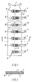
- Fig. 1 shows schematically a device 1 according to the invention which is particularly suited for use in closing an incision in a body in connection with autopsy.
- the width of the device will typically be 12 to 20 cm and the length 60 to 80 cm, but the device might also have been made with a length up to 90 cm or up to 100 cm. If the device is too long for fitting a given body, the surplus length may simply be cut off.
- Fig. 2 which is a sectional view along the line II-II in Fig. 1, the device comprises a flexible sheet of material 2 with a surface 3 which is intended to face the body, and an opposite surface 4 which is intended to turn away from the body.
- An adhesive 5 has been applied to the body facing surface, said adhesive being covered by a sheet of release paper or foil 16, for instance in form of waxed or siliconized paper or foil.
- the device 1 is adhesively attached to the body in such a way that it is positioned on both sides of the incision trace 6, illustrated by a broken line in Fig. 1.
- a row of closing means 7 On one side of the incision trace a row of closing means 7 has been provided which cooperates with a row of closing means 8 arranged on the other side of the incision trace 6, one means 7i positioned on one side of the incision trace cooperating with a means 8i positioned oppositely on the other side of the incision trace.
- the closing means 7, 8 are designed in such a way that the two means 7i, 8i in a pair independently of the other pairs of mutually cooperating means may be brought into operative connection with each other for closing of the incision.
- FIG. 3 Further details of the closing means 7,8 shown in Fig. 1 appear from Figs. 3 and 4.
- the closing means 7 is equipped with a strap-like element 11, the full length of which is not shown in Fig. 3.
- the closing means 8 is equipped with an eye- or loop-shaped guiding device 12, through which the strap-like element may be passed, following which it is then taken back in direction towards the closing means 7, such that a pull in the strap-like element 11 in this direction will subject the closing means 7, 8 to in a direction towards each other simultaneously acting incision closing forces substantially without any other impact on the area around the incision in the direction of the incision trace than what might be necessary for bringing the two means of a pair in line with each other.
- This pull may be exerted by one hand, which leaves the other hand of the surgeon free to bear against the body, which is not least of considerable importance when closing a longitudinal incision in a body in connection with autopsy.
- the strap-like element 11 is on the side not shown equipped with locking means 9 in form of a row of transverse ribs 18 (indicated by broken lines), which when the strap-like element 11 is passed through the slot formed by the eye or loop 12 is brought into engagement with a catch protrusion 10, whereby the means 7, 8 are locked relative to each other.
- the ribs 18 do not have to be spaced with the same distance, but may for instance be placed with a shorter distance on the interior part, where the final tightening takes place. It may also just be a question of separate ribs arranged in predetermined locking positions. The locking may be released by a continued pull in the strap-like element 11.
- the strap-like element 11 is provided with a hole 13 which when the strap-like element is bent backwards, away from the incision trace, may be brought into engagement with a tap 14 on the means 7. In this way the strap-like element 11 is safely kept away from the incision trace while the incision is being made.
- the means 7 is made from a material which is sufficiently resilient to make the transition between the fixed part 17 of the means 7 and the strap-like element act like a hinge. Nylon, polyethylene, and polypropylene are examples of such materials.
- the fixed part 17 of the means 7 is provided with a pair of protrusions 15 serving as guides for the scalpel, while the incision is being made, the backwards bent strap-like element 11 being protected at the same time.
- Fig. 5 is a lateral view of the closing means according to Fig. 3 in closed condition. If desired, the strap-like element may be shortened after the closing has taken place.
- Fig. 6 and 7 illustrate an alternative embodiment of the closing means according to the invention, elements having the same function as elements shown in Figs. 1-5 being indicated by the same reference numerals for the sake of simplicity.
- the means for releasable closing of the closing means of a pair are a row of holes 9 arranged in the strap-like element 11, which, as shown in Fig. 7, is brought into engagement with a tap 10 on the means 7 with the strap-like element, the strap-like element having been passed through an eye or loop 12 on the means 8.
- the locking may be released by a continued pull in the strap-like element 11 in the direction of the arrow shown in Fig. 7.
- the holes 9 and the tap 10 may optionally be designed in such manner that they may both be used for keeping the strap-like element 11 free of the incision trace, while the incision is being made, and for locking of the means 7, 8 relative to each other after the passing of the strap-like element 11 around the eye or loop 12.
- Fig. 8 shows the device according to Fig. 1 but after it has been used for closing an incision tracewise of a body in connection with autopsy. It will be seen how the incision line and the closing means which have been used for closing the incision are covered by a further sheet of material 22 adhesively attached to the device 1. It is moreover seen how the device 1 comprises a substantially rectangular elongate portion A which at one end merges into a portion B having side lines converging towards the centre line, which portion ends in a neck portion C with an obliquely outwards directed flap portion 19, 20 on each side of the centre line. Furthermore, a indentation 21 is provided in the neck portion C for receiving the curvature of a neck.
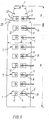
- Figs. 9 and 10 show in combination another embodiment of the device according to the invention, in which the neck portion C is formed as a separate unit.
- the neck portion C is substantially trapezoidal, as it has the shape of a trapezium, the corners of which at the base line of the trapezium being cut off and replaced by flap portions 19, 20 having a width of 1 - 2 cm.
- the device 1 comprises a substantially rectangular elongate portion A which at one end merges into a portion B with side lines converging towards the centre line.
- the ratio between the distance c, spanned by the flap portions 19, 20 and the intermediate part of the neck portion, and the width b of the portion B in Fig. 9, where the distance between the substantially converging side lines is smallest, is in the embodiment shown about 5.5, and the ratio between the width a of the portion A and the above-mentioned width b is about 2.
- the device 1 shown in Fig. 9 is in principle constructed in the same way as the device shown in Fig. 1, but the closing means are of another type.
- both the closing means 7 and the closing means 8 comprise a guiding device 12 of the type shown in Figs. 3 and 5, whereas the strap-like element 11 is formed as a separate unit intended to be passed through both the guiding device 12 on the closing means 8 and the guiding device 12 on the closing means 7.
- the strap-like element 11 is at one end provided with a stop member 24.
- the strap-like element 11 is provided with one or more ribs, by means of which it may be brought into locking engagement with the guiding device 12 on the opposite side of the incision trace 6.
- the closing means 7, 8 are designed with a comparatively large base to prevent delamination of the subjacent skin during the considerable impact of force occurring during the closing operation.
- the closing means are moreover arranged with a certain mutual spacing in a direction transversal to the incision trace, which does not only make it possible to tighten the tissue to the position, in which it was prior to the making of the incision, but to perform a further tightening, whereby the incision edges with the adhesively attached, flexible sheet of material and the subjacent skin are bent down into the incision area, and the upper surface of the edge areas of the sheet of material on each side of the incision trace abut each other, thereby contributing to an improved sealing.
- the edge area of the closing means 7, 8 facing the incision trace has been bevelled to facilitate the bending down in the incision area.
- edges running along the side lines of the portion B are provided with notches or indentations 23 for facilitating the adaptation to the contour of the body in the area in question.
- the notches or the indentations have been made by removal of a part of the sheet of material to reduce the risk of unintentional sticking together of the edges.
- Figs. 11 and 12 show additional flexible sheets of material 22, which are on one surface provided with a layer of a hydrocolloid-containing adhesive, which layer of adhesive is covered by a sheet of release paper or foil.
- the sheet of material shown in Fig. 11 is intended to be adhesively attached immediately over the incision area after closing of an incision by means of the device 1.
- the sheet of material shown in Fig. 12 is intended to be adhesively attached after the sheet of material shown in Fig. 11 and such that it covers said sheet of material and the closing means 7, 8.
- the device shown in Fig. 12 is in a similar way as the device 1 provided with notches or indentations 23 in the side edge at the end intended to face the neck.
Landscapes
- Health & Medical Sciences (AREA)
- Life Sciences & Earth Sciences (AREA)
- Surgery (AREA)
- Public Health (AREA)
- Heart & Thoracic Surgery (AREA)
- Medical Informatics (AREA)
- Molecular Biology (AREA)
- Biomedical Technology (AREA)
- Animal Behavior & Ethology (AREA)
- General Health & Medical Sciences (AREA)
- Engineering & Computer Science (AREA)
- Veterinary Medicine (AREA)
- Nuclear Medicine, Radiotherapy & Molecular Imaging (AREA)
- Materials For Medical Uses (AREA)
- Surgical Instruments (AREA)
- Slot Machines And Peripheral Devices (AREA)
- Manufacture, Treatment Of Glass Fibers (AREA)
- Molding Of Porous Articles (AREA)
- Harvester Elements (AREA)
- Portable Nailing Machines And Staplers (AREA)
- Cable Accessories (AREA)
Claims (41)
- Un dispositif (1) pouvant être utilisé pour la fermeture d'une incision pratiquée dans un corps en rapport avec une autopsie, en particulier une incision longitudinale le long de la ligne médiane du corps, lequel dispositif comprend au moins une feuille flexible de matériau (2) avec une face (3) destinée à être tournée vers le corps et une face opposée (4) destinée à être tournée vers l'extérieur du corps, la face tournée vers le corps étant fournie avec un adhésif (5), au moyen duquel le dispositif peut être fixé au corps de manière adhésive de telle manière que le dispositif soit présent des deux côtés de la ligne d'incision (6), et lequel dispositif comprend deux rangées de moyens fonctionnant de manière complémentaire (7, 8) devant servir à fermer l'incision, lesdites rangées de moyens de fermeture étant présentes de chaque côté de la ligne d'incision (6) et permettant de pratiquer l'incision après la fixation adhésive du dispositif, ledit dispositif étant caractérisé par le fait que ladite au moins une feuille de matériau (2) comprend une portion (C) destinée à être fixée de manière adhésive à la zone du cou du corps, laquelle portion destinée au cou (C) comprend une portion en volet s'étendant vers l'extérieur (19, 20) de chaque côté d'une ligne correspondant à la ligne médiane du corps, et par le fait que ladite au moins une feuille de matériau (2) à l'extrémité faisant face à la portion destinée au cou (C) comprend une portion (B), dont les lignes latérales en direction de la portion destinée au cou (C) convergent de essentiellement vers la ligne correspondant à la ligne médiane du corps.
- Un dispositif tel que revendiqué dans la revendication 1,
caractérisé par le fait que les portions en volet s'étendant vers l'extérieur (19, 20) ont une longueur telle qu'avec la partie intermédiaire de la portion destinée au cou, elles couvrent une distance (c) d'au moins 25 cm, de préférence d'au moins 35 cm, et en particulier une distance de 40-55 cm. - Un dispositif tel que revendiqué dans la revendication 1 ou 2,
caractérisé par le fait que le rapport entre la distance (c), que couvrent les portions en volet s'étendant vers l'extérieur (19, 20) avec la partie intermédiaire de la portion destinée au cou, et la largeur (b) de la portion (B), là où la distance entre les lignes latérales essentiellement convergentes est la plus petite, est d'environ 1,5 ou plus. - Un dispositif tel que revendiqué dans une ou plusieurs des revendications précédentes, caractérisé par le fait que les portions en volet (19, 20) s'étendent à l'oblique vers l'extérieur et vers le haut, respectivement par rapport à une ligne correspondant à la ligne médiane du corps et par rapport à l'orientation du corps placé en position droite.
- Un dispositif tel que revendiqué dans une ou plusieurs des revendications précédentes, caractérisé par le fait que la portion destinée au cou (C) est réalisée sous forme d'une unité séparée.
- Un dispositif tel que revendiqué dans une ou plusieurs des revendications précédentes, caractérisé par le fait que la portion destinée au cou (C) est essentiellement trapézoïdale.
- Un dispositif tel que revendiqué dans une ou plusieurs des revendications précédentes, caractérisé par le fait que la portion destinée au cou (C) est fournie avec une indentation (21) destinée à accueillir la courbure d'un cou.
- Un dispositif tel que revendiqué dans la revendication 6,
caractérisé par le fait que les bords longeant les lignes latérales de la portion (B) sont fournis avec des encoches ou des indentations (23). - Un dispositif tel que revendiqué dans la revendication 8,
caractérisé par le fait que les encoches ou les indentations (23) sont réalisées en retirant une partie de la feuille de matériau (2). - Un dispositif tel que revendiqué dans une ou plusieurs des revendications précédentes, caractérisé par le fait que ladite au moins une feuille de matériau (2) à l'extrémité tournée à l'opposé de la portion destinée au cou (C) comprend une portion oblongue essentiellement rectangulaire (A).
- Un dispositif tel que revendiqué dans la revendication 10,
caractérisé par le fait que le rapport entre la largeur (a) de la portion (A) et la largeur (b) de la portion (B), là où la distance entre les lignes latérales essentiellement convergeantes est la plus petite, est d'environ 1,2 ou plus, de préférence d'environ 1,5 ou plus, et en particulier de 1,5 à 2,5. - Un dispositif tel que revendiqué dans une ou plusieurs des revendications précédentes, caractérisé par le fait que les moyens de fermeture (7, 8) fonctionnent par paires, un moyen (7i) positionné d'un côté de la ligne d'incision fonctionnant avec un moyen (8i) positionné à l'opposé de l'autre côté de la ligne d'incision, et les deux moyens d'une même paire, indépendamment des autres paires de moyens de fermeture, peuvent être connectés de manière opérante pour fermer l'incision.
- Un dispositif tel que revendiqué dans la revendication 12, caractérisé par le fait que le moyen de fermeture d'une paire est fourni avec des moyens (9, 10) pour déclencher le verrouillage dudit moyen de fermeture avec l'autre moyen au cours de l'opération de fermeture.
- Un dispositif tel que revendiqué dans la revendication 12 ou 13, caractérisé par le fait qu'un moyen d'une paire comprend un élément de type courroie (11) et l'autre moyen d'une paire comprend un dispositif de guidage (12) autour ou au travers duquel l'élément de type courroie peut être passé, de manière à ce qu'une traction sur l'élément de type courroie soit capable de produire une force de fermeture de l'incision essentiellement sans produire tout autre impact sur la zone autour de l'incision dans la direction de la ligne d'incision que ce qui pourrait être nécessaire pour aligner les deux moyens d'une paire l'un avec l'autre.
- Un dispositif tel que revendiqué dans la revendication 14, caractérisé par le fait que le moyen de fermeture avec l'élément de type courroie est fourni avec des moyens (13, 14) pour maintenir l'élément de type courroie à distance de la ligne d'incision lors de la réalisation de l'incision.
- Un dispositif tel que revendiqué dans la revendication 15,
caractérisé par le fait que les moyens (13, 14) pour maintenir l'élément de type courroie à distance de la ligne d'incision lors de la réalisation de l'incision ont la forme d'un agencement de trou taraudé, d'un agencement de boutonnière, d'un dispositif de clampage, d'un bouton à pression, d'une courroie, d'un ruban adhésif, d'un adhésif et/ou d'un "Velcro". - Un dispositif tel que revendiqué dans la revendication 14, caractérisé par le fait que le moyen de fermeture avec l'élément de type courroie (11) est fourni avec des moyens (15) pour maintenir l'outil d'incision à distance de l'élément de type courroie lors de la réalisation de l'incision.
- Un dispositif tel que revendiqué dans une ou plusieurs des revendications précédentes, caractérisé par le fait que les moyens de fermeture (7, 8) sont agencés avec un espacement mutuel d'au moins 15 mm, de préférence au moins 20 mm, dans une direction transversale par rapport à la ligne d'incision.
- Un dispositif tel que revendiqué dans une ou plusieurs des revendications précédentes, caractérisé par le fait que la largeur de la base des moyens de fermeture (7, 8) est d'au moins 15 mm, de préférence d'au moins 20 mm, et en particulier d'au moins 25 mm, et par le fait que la longueur de la base des moyens de fermeture (7, 8) est d'au moins 15 mm, de préférence d'au moins 20 mm, et en particulier d'au moins 25 mm.
- Un dispositif tel que revendiqué dans une ou plusieurs des revendications précédentes, caractérisé par le fait que le bord de la base des moyens de fermeture (7, 8) faisant face à la ligne d'incision est flexible.
- Un dispositif tel que revendiqué dans une ou plusieurs des revendications précédentes, caractérisé par le fait que l'un des moyens de fermeture (7, 8) comprend un élément de type courroie (11), qui est fourni avec au moins deux nervures ou cames (18), dont l'une correspond à une position complètement fermée et l'autre correspond à une position intermédiaire, et par le fait que l'autre moyen de fermeture (7, 8) comprend une boucle à cliquet.
- Un dispositif tel que revendiqué dans la revendication 21,
caractérisé par le fait que l'élément de type courroie et la boucle à cliquet sont fixés au moins à 2 mm de distance du bord de la base du moyen de fermeture faisant face à la ligne d'incision. - Un dispositif tel que revendiqué dans une ou plusieurs des revendications précédentes, caractérisé par le fait que les moyens fonctionnant de manière complémentaire (7, 8) comprennent des dispositifs de guidage (12), qui sont positionnés de chaque côté de la ligne d'incision, et des éléments de type courroie séparés (11), par l'intermédiaire desquels les moyens fonctionnant de manière complémentaire (7, 8) peuvent être connectés par paires de manière opérante l'un à l'autre afin de fermer l'incision, lesdits éléments de type courroie (11) étant fournis avec un membre d'arrêt (24) adapté pour empêcher l'élément de type courroie de passer à la transversale par le dispositif de guidage (12) d'un côté de la ligne d'incision et l'amener dans la prise de verrouillage avec le dispositif de guidage (12) de l'autre côté de la ligne d'incision dans au moins une position.
- Un dispositif tel que revendiqué dans les revendications 12-23, caractérisé par le fait que les moyens de fermeture (7, 8) sont conçus de telle manière que lorsque les deux moyens (7i, 8i) d'une paire ont été connectés de manière opérante l'un à l'autre, il soit possible, en tirant d'une seule main sur l'un des moyens de la paire, d'appliquer aux deux moyens de la paire, dans une direction les rapprochant l'un de l'autre, des forces de fermeture de l'incision agissant simultanément, essentiellement sans produire tout autre impact sur la zone autour de l'incision dans la direction de la ligne d'incision que ce qui pourrait être nécessaire pour aligner les deux moyens d'une paire l'un avec l'autre.
- Un dispositif tel que revendiqué dans les revendications 13-24, caractérisé par le fait que les moyens (9, 10) pour déclencher le verrouillage du moyen d'une paire sont de type boucle à cliquet, boucle à bande, boucle à crochet, boutonnière, trou taraudé, bouton à pression ou "Velcro".
- Un dispositif tel que revendiqué dans les revendications 13-25, caractérisé par le fait que les moyens (9, 10) pour déclencher le verrouillage des moyens de fermeture d'une paire sont positionnés sur les moyens de fermeture avec l'élément de type courroie (11).
- Un dispositif tel que revendiqué dans les revendications 13-26, caractérisé par le fait que les moyens (9, 10) pour déclencher le verrouillage des moyens d'une paire sont fournis en partie sur un moyen de la paire et en partie sur l'autre.
- Un dispositif tel que revendiqué dans les revendications 12-27, caractérisé par le fait que le verrouillage des moyens d'une paire l'un avec l'autre peut être déclenché essentiellement sans aucune force de traction dans une direction perpendiculaire au plan de la feuille de matériau.
- Un dispositif tel que revendiqué dans la revendication 28,
caractérisé par le fait que le verrouillage peut être déclenché par une traction continue sur l'un des moyens de la paire. - Un dispositif tel que revendiqué dans une ou plusieurs des revendications précédentes, caractérisé par le fait que la feuille de matériau (2) est continue dans la zone où l'incision doit être pratiquée.
- Un dispositif tel que revendiqué dans une ou plusieurs des revendications précédentes, caractérisé par le fait que la feuille de matériau (2) est une feuille de polyuréthane, d'EAV (éthylène/acétate de vinyle), avec une teneur élevée en acétate de vinyle, en polyéthylène chloré ou en PVC plastifié.
- Un dispositif tel que revendiqué dans une ou plusieurs des revendications précédentes, caractérisé par le fait que l'adhésif (5) est un adhésif contenant de l'hydrocolloïde.
- Un dispositif tel que revendiqué dans une ou plusieurs des revendications précédentes, caractérisé par le fait que l'adhésif sur la face tournée vers le corps est couvert d'une feuille de papier ou film anti-adhésif.
- Un dispositif tel que revendiqué dans une ou plusieurs des revendications précédentes, caractérisé par le fait que la portion destinée au cou (C) est fournie avec deux rangées de moyens fonctionnant de manière complémentaire (7, 8), s'étendant jusque dans les volets dirigés vers l'extérieur (19, 20) pour utilisation dans la fermeture d'une incision pratiquée à la transversale de la ligne médiane du corps.
- Un ensemble comprenant un dispositif tel que revendiqué dans une ou plusieurs des revendications précédentes, ainsi qu'une feuille de matériau supplémentaire flexible, de préférence de la couleur de la peau et de préférence non transparente (22) de dimensions telles qu'après la fermeture d'une incision au moyen dudit dispositif, elle puisse recouvrir la zone de l'incision et de préférence également les moyens de fermeture (7, 8), une couche d'adhésif ayant été appliqué sur l'une des faces de ladite feuille de matériau supplémentaire, ladite couche adhésive étant recouverte d'une feuille de papier ou film anti-adhésif.
- Un ensemble tel que revendiqué dans la revendication 35,
caractérisé par le fait qu'il comprend deux feuilles de matériau supplémentaires (22), la première d'entre elles ayant des dimensions telles qu'après la fermeture d'une incision au moyen dudit dispositif, elle puisse recouvrir la zone de l'incision, et la seconde ayant des dimensions telles qu'après la fermeture d'une incision au moyen dudit dispositif et après que la première feuille de matériau supplémentaire ait adhéré à l'ensemble de la zone de l'incision, elle puisse recouvrir les moyens de fermeture (7, 8). - Un ensemble tel que revendiqué dans la revendication 35 ou 36,
caractérisé par le fait qu'au moins une des feuilles de matériau supplémentaires (22) a été fournie avec un adhésif tel que revendiqué dans la revendication 32. - Un ensemble tel que revendiqué dans une ou plusieurs des revendications 35-37, caractérisé par le fait que la feuille de matériau supplémentaire (22) ou au moins l'une des feuilles de matériau supplémentaires (22), située immédiatement au-dessus de la zone de l'incision, a été fournie avec une couche adhésive, qui est plus épaisse, de préférence au moins deux fois plus épaisse, et en particulier au moins 3-5 fois plus épaisse que la couche adhésive sur le dispositif lui-même.
- Un ensemble tel que revendiqué dans une ou plusieurs des revendications 35-38, caractérisé par le fait qu'il comprend une feuille de matériau supplémentaire (22) de dimensions telles qu'après fermeture d'une incision au moyen du dispositif (1), elle puisse essentiellement recouvrir la zone de l'incision et les moyens de fermeture, ladite feuille de matériau supplémentaire ayant des coins arrondis à l'extrémité destinée à faire face au cou et étant à cette fin équipée d'encoches ou d'indentations (23) sur le bord latéral.
- Un ensemble tel que revendiqué dans la revendication 39,
caractérisé par le fait que les encoches ou les indentations (23) sont réalisées en retirant une partie de la feuille de matériau (2). - Une méthode de fermeture d'une incision pratiquée dans un corps en rapport avec une autopsie, en particulier une incision longitudinale le long de la ligne médiane du corps,
caractérisée par le fait qu'avant de pratiquer l'incision, un dispositif (1) tel que revendiqué dans une ou plusieurs des revendications 1-34 est fixé de manière adhésive au corps de telle manière que le dispositif soit positionné des deux côtés de la ligne d'incision prévue (6), les deux rangées de moyens fonctionnant de manière complémentaire (7, 8) étant positionnées de chaque côté de la ligne d'incision et la portion destinée au cou (C) étant fixée de manière adhésive à la zone du cou du corps avec les volets s'étendant vers l'extérieur (19, 20) placés autour du cou, éventuellement d'une manière telle qu'ils se chevauchent, qu'après la réalisation de l'incision, les moyens fonctionnant de manière complémentaire soient connectés de manière opérante l'un à l'autre pour fermer l'incision, les moyens fonctionnant en paires étant, si désiré, actionnés l'un après l'autre pour permettre une fermeture progressive contrôlée de l'incision lors du déclenchement du verrouillage dans au moins une position intermédiaire, et l'opération de verrouillage étant, si désiré, continuée au-delà de la position de départ de telle manière que les bords de l'incision avec la feuille de matériau fixée de manière adhésive et la peau sous-jacente soient inclinés vers le bas jusque dans la zone de l'incision et que les bords de la feuille de matériau de chaque côté de la ligne d'incision se touchent, et par le fait que, si désiré, après avoir éventuellement essuyé le côté supérieur du dispositif, une ou plusieurs feuilles de matériau supplémentaires (22) telles que revendiquées dans les revendications 35-40 soient fixées de manière adhésive afin de recouvrir la zone de l'incision, et de préférence également les moyens de fermeture (7, 8).
Applications Claiming Priority (3)
| Application Number | Priority Date | Filing Date | Title |
|---|---|---|---|
| DK28195 | 1995-03-20 | ||
| DK28195 | 1995-03-20 | ||
| PCT/DK1996/000098 WO1996029013A1 (fr) | 1995-03-20 | 1996-03-08 | Dispositif et procede de fermeture d'une incision dans un corps soumis a une autopsie |
Publications (2)
| Publication Number | Publication Date |
|---|---|
| EP0957774A1 EP0957774A1 (fr) | 1999-11-24 |
| EP0957774B1 true EP0957774B1 (fr) | 2002-06-12 |
Family
ID=8091796
Family Applications (1)
| Application Number | Title | Priority Date | Filing Date |
|---|---|---|---|
| EP96905758A Expired - Lifetime EP0957774B1 (fr) | 1995-03-20 | 1996-03-08 | Dispositif et procede adaptes pour fermer une incision dans un corps soumis a une autopsie |
Country Status (7)
| Country | Link |
|---|---|
| EP (1) | EP0957774B1 (fr) |
| AT (1) | ATE218837T1 (fr) |
| AU (1) | AU4939096A (fr) |
| DE (1) | DE69621846T2 (fr) |
| DK (1) | DK0957774T3 (fr) |
| NO (1) | NO974329L (fr) |
| WO (1) | WO1996029013A1 (fr) |
Cited By (1)
| Publication number | Priority date | Publication date | Assignee | Title |
|---|---|---|---|---|
| CN104490434A (zh) * | 2014-12-03 | 2015-04-08 | 江门市富美尔环保电子科技有限公司 | 医用缝合拉扣 |
Families Citing this family (26)
| Publication number | Priority date | Publication date | Assignee | Title |
|---|---|---|---|---|
| US8157839B2 (en) | 2004-08-31 | 2012-04-17 | Wadsworth Medical Technologies, Inc. | Systems and methods for closing a tissue opening |
| BRPI0709908A2 (pt) * | 2006-03-31 | 2013-02-26 | Univ Nanyang Tech | afastador de tecido, kit de afastador de tecido e mÉtodo de uso do mesmo |
| US20090264709A1 (en) | 2008-04-21 | 2009-10-22 | Plexus Biomedical, Inc. | Method and Apparatus for Retention of Adipose Tissue |
| CA2773915A1 (fr) | 2009-09-17 | 2011-04-14 | Zipline Medical, Inc. | Dispositif de fermeture chirurgicale rapide |
| US10159825B2 (en) | 2009-09-17 | 2018-12-25 | Zipline Medical, Inc. | Rapid closing surgical closure device |
| AU2011267977B2 (en) | 2010-06-14 | 2015-02-05 | Zipline Medical, Inc. | Methods and apparatus for inhibiting scar formation |
| US20120167360A1 (en) * | 2011-01-04 | 2012-07-05 | Phyliss Dralle | Post mortem sheet and method |
| CA2834930C (fr) | 2011-05-03 | 2019-04-30 | Wadsworth Medical Technologies, Inc. | Dispositifs pour fermer de facon sure des ouvertures de tissu presentant cicatrisation reduite au minimum |
| US9561034B2 (en) | 2011-11-01 | 2017-02-07 | Zipline Medical, Inc. | Surgical incision and closure apparatus |
| US8323313B1 (en) * | 2011-11-01 | 2012-12-04 | Zipline Medical, Inc. | Surgical incision and closure apparatus with integrated force distribution |
| US12171432B2 (en) | 2011-11-01 | 2024-12-24 | Zipline Medical, Inc. | Closure apparatuses and methods for ulcers and irregular skin defects |
| US10123800B2 (en) | 2011-11-01 | 2018-11-13 | Zipline Medical, Inc. | Surgical incision and closure apparatus with integrated force distribution |
| US9050086B2 (en) | 2011-11-01 | 2015-06-09 | Zipline Medical, Inc. | Surgical incision and closure apparatus |
| US10123801B2 (en) | 2011-11-01 | 2018-11-13 | Zipline Medical, Inc. | Means to prevent wound dressings from adhering to closure device |
| EP2914183B1 (fr) * | 2012-10-31 | 2019-04-17 | Zipline Medical, Inc. | Appareil chirurgicale de fermeture |
| US8597306B1 (en) | 2013-03-14 | 2013-12-03 | Plexus Biomedical, Inc. | Labor management methods for decreasing the incidence of cesarean childbirth |
| CN105873525A (zh) | 2014-01-05 | 2016-08-17 | 奇普林医药公司 | 仪表化伤口闭合装置 |
| US9662112B2 (en) | 2014-02-10 | 2017-05-30 | Alan E. Nash | System for closing a wound |
| CN103948407B (zh) * | 2014-05-20 | 2016-03-02 | 李绪国 | 一种创口闭合器 |
| US10080520B2 (en) | 2015-02-27 | 2018-09-25 | Stetrix, Inc. | Labor monitoring of pelvic floor |
| CN106214199A (zh) * | 2016-10-11 | 2016-12-14 | 常州纳森医疗器械有限公司 | 一种无针皮肤吻合器 |
| WO2018081795A1 (fr) | 2016-10-31 | 2018-05-03 | Zipline Medical, Inc. | Systèmes et procédés de surveillance d'une thérapie physique du genou et d'autres articulations |
| US9993382B1 (en) | 2017-07-10 | 2018-06-12 | Stetrix, Inc. | Tissue retention systems and methods |
| GB2574074B (en) | 2018-07-27 | 2020-05-20 | Mclaren Applied Tech Ltd | Time synchronisation |
| US12096937B2 (en) | 2019-04-25 | 2024-09-24 | Dq Holdings, Llc | Skin closure devices |
| GB2588236B (en) | 2019-10-18 | 2024-03-20 | Mclaren Applied Ltd | Gyroscope bias estimation |
Family Cites Families (5)
| Publication number | Priority date | Publication date | Assignee | Title |
|---|---|---|---|---|
| US3698395A (en) * | 1971-03-12 | 1972-10-17 | Harrith M Hasson | Surgical closure |
| US3971384A (en) * | 1971-03-12 | 1976-07-27 | Hasson Harrith M | Surgical closure |
| US3926193A (en) * | 1971-12-17 | 1975-12-16 | Harrith M Hasson | Surgical closure having ease of assembly |
| US4531521A (en) * | 1983-03-03 | 1985-07-30 | Haverstock Charles B | Skin closure means |
| US4976726A (en) * | 1989-04-27 | 1990-12-11 | Haverstock Charles B | Skin closure devices |
-
1996
- 1996-03-08 AU AU49390/96A patent/AU4939096A/en not_active Abandoned
- 1996-03-08 EP EP96905758A patent/EP0957774B1/fr not_active Expired - Lifetime
- 1996-03-08 DK DK96905758T patent/DK0957774T3/da active
- 1996-03-08 AT AT96905758T patent/ATE218837T1/de not_active IP Right Cessation
- 1996-03-08 WO PCT/DK1996/000098 patent/WO1996029013A1/fr not_active Ceased
- 1996-03-08 DE DE69621846T patent/DE69621846T2/de not_active Expired - Fee Related
-
1997
- 1997-09-19 NO NO974329A patent/NO974329L/no not_active Application Discontinuation
Cited By (1)
| Publication number | Priority date | Publication date | Assignee | Title |
|---|---|---|---|---|
| CN104490434A (zh) * | 2014-12-03 | 2015-04-08 | 江门市富美尔环保电子科技有限公司 | 医用缝合拉扣 |
Also Published As
| Publication number | Publication date |
|---|---|
| DE69621846T2 (de) | 2002-12-19 |
| DK0957774T3 (da) | 2002-07-15 |
| EP0957774A1 (fr) | 1999-11-24 |
| NO974329D0 (no) | 1997-09-19 |
| NO974329L (no) | 1997-11-20 |
| AU4939096A (en) | 1996-10-08 |
| DE69621846D1 (de) | 2002-07-18 |
| WO1996029013A1 (fr) | 1996-09-26 |
| ATE218837T1 (de) | 2002-06-15 |
Similar Documents
| Publication | Publication Date | Title |
|---|---|---|
| EP0957774B1 (fr) | Dispositif et procede adaptes pour fermer une incision dans un corps soumis a une autopsie | |
| US6187126B1 (en) | Method for making a refastenable tube and cable restraint | |
| EP0749335B1 (fr) | Attache refixable pour tubes et liens a usage chirurugical | |
| EP0870488B1 (fr) | Pansement à couche mince avec une couche arrière extensible perforée | |
| US4038989A (en) | Surgical skin closure | |
| JP7296028B2 (ja) | 力変調組織ブリッジ、関連するツール、キット、および方法 | |
| US11805972B2 (en) | Wound closure system | |
| JP2007505664A (ja) | オストミー装置の連結 | |
| US5968024A (en) | Ostomy appliance and wound drainage device with self adhering drain system | |
| US20030153882A1 (en) | Ostomy pouch with bias members and closure means | |
| WO1997001311A1 (fr) | Genouillere elastique | |
| KR101564648B1 (ko) | 봉합장치 | |
| KR20140123101A (ko) | 수술용 스테이플 라인 보강부를 공급하는 장치 | |
| KR20190084257A (ko) | 상처 봉합 조성물 및 상처 봉합 조성물로 제조된 상처 봉합 장치 | |
| WO2014126843A2 (fr) | Système de fermeture d'une plaie | |
| US20130345744A1 (en) | Wound closure device | |
| EP0353904A1 (fr) | Système d'ostomie | |
| EP2858707A1 (fr) | Dispositif pour pansement | |
| CN215839067U (zh) | 一种采血辅助装置 | |
| JP3621138B2 (ja) | 傷口封鎖装置 |
Legal Events
| Date | Code | Title | Description |
|---|---|---|---|
| PUAI | Public reference made under article 153(3) epc to a published international application that has entered the european phase |
Free format text: ORIGINAL CODE: 0009012 |
|
| 17P | Request for examination filed |
Effective date: 19970909 |
|
| AK | Designated contracting states |
Kind code of ref document: A1 Designated state(s): AT BE CH DE DK ES FI FR GB GR IE IT LI LU NL PT SE |
|
| GRAG | Despatch of communication of intention to grant |
Free format text: ORIGINAL CODE: EPIDOS AGRA |
|
| 17Q | First examination report despatched |
Effective date: 20010517 |
|
| GRAG | Despatch of communication of intention to grant |
Free format text: ORIGINAL CODE: EPIDOS AGRA |
|
| GRAG | Despatch of communication of intention to grant |
Free format text: ORIGINAL CODE: EPIDOS AGRA |
|
| GRAH | Despatch of communication of intention to grant a patent |
Free format text: ORIGINAL CODE: EPIDOS IGRA |
|
| GRAH | Despatch of communication of intention to grant a patent |
Free format text: ORIGINAL CODE: EPIDOS IGRA |
|
| GRAA | (expected) grant |
Free format text: ORIGINAL CODE: 0009210 |
|
| AK | Designated contracting states |
Kind code of ref document: B1 Designated state(s): AT BE CH DE DK ES FI FR GB GR IE IT LI LU NL PT SE |
|
| PG25 | Lapsed in a contracting state [announced via postgrant information from national office to epo] |
Ref country code: NL Free format text: LAPSE BECAUSE OF FAILURE TO SUBMIT A TRANSLATION OF THE DESCRIPTION OR TO PAY THE FEE WITHIN THE PRESCRIBED TIME-LIMIT Effective date: 20020612 Ref country code: LI Free format text: LAPSE BECAUSE OF FAILURE TO SUBMIT A TRANSLATION OF THE DESCRIPTION OR TO PAY THE FEE WITHIN THE PRESCRIBED TIME-LIMIT Effective date: 20020612 Ref country code: IT Free format text: LAPSE BECAUSE OF FAILURE TO SUBMIT A TRANSLATION OF THE DESCRIPTION OR TO PAY THE FEE WITHIN THE PRESCRIBED TIME-LIMIT;WARNING: LAPSES OF ITALIAN PATENTS WITH EFFECTIVE DATE BEFORE 2007 MAY HAVE OCCURRED AT ANY TIME BEFORE 2007. THE CORRECT EFFECTIVE DATE MAY BE DIFFERENT FROM THE ONE RECORDED. Effective date: 20020612 Ref country code: GR Free format text: LAPSE BECAUSE OF FAILURE TO SUBMIT A TRANSLATION OF THE DESCRIPTION OR TO PAY THE FEE WITHIN THE PRESCRIBED TIME-LIMIT Effective date: 20020612 Ref country code: FI Free format text: LAPSE BECAUSE OF FAILURE TO SUBMIT A TRANSLATION OF THE DESCRIPTION OR TO PAY THE FEE WITHIN THE PRESCRIBED TIME-LIMIT Effective date: 20020612 Ref country code: CH Free format text: LAPSE BECAUSE OF FAILURE TO SUBMIT A TRANSLATION OF THE DESCRIPTION OR TO PAY THE FEE WITHIN THE PRESCRIBED TIME-LIMIT Effective date: 20020612 Ref country code: BE Free format text: LAPSE BECAUSE OF FAILURE TO SUBMIT A TRANSLATION OF THE DESCRIPTION OR TO PAY THE FEE WITHIN THE PRESCRIBED TIME-LIMIT Effective date: 20020612 Ref country code: AT Free format text: LAPSE BECAUSE OF FAILURE TO SUBMIT A TRANSLATION OF THE DESCRIPTION OR TO PAY THE FEE WITHIN THE PRESCRIBED TIME-LIMIT Effective date: 20020612 |
|
| REF | Corresponds to: |
Ref document number: 218837 Country of ref document: AT Date of ref document: 20020615 Kind code of ref document: T |
|
| REG | Reference to a national code |
Ref country code: GB Ref legal event code: FG4D |
|
| REG | Reference to a national code |
Ref country code: CH Ref legal event code: EP |
|
| REG | Reference to a national code |
Ref country code: DK Ref legal event code: T3 |
|
| REF | Corresponds to: |
Ref document number: 69621846 Country of ref document: DE Date of ref document: 20020718 |
|
| REG | Reference to a national code |
Ref country code: IE Ref legal event code: FG4D |
|
| PG25 | Lapsed in a contracting state [announced via postgrant information from national office to epo] |
Ref country code: SE Free format text: LAPSE BECAUSE OF FAILURE TO SUBMIT A TRANSLATION OF THE DESCRIPTION OR TO PAY THE FEE WITHIN THE PRESCRIBED TIME-LIMIT Effective date: 20020912 |
|
| PG25 | Lapsed in a contracting state [announced via postgrant information from national office to epo] |
Ref country code: PT Free format text: LAPSE BECAUSE OF FAILURE TO SUBMIT A TRANSLATION OF THE DESCRIPTION OR TO PAY THE FEE WITHIN THE PRESCRIBED TIME-LIMIT Effective date: 20020916 |
|
| NLV1 | Nl: lapsed or annulled due to failure to fulfill the requirements of art. 29p and 29m of the patents act | ||
| ET | Fr: translation filed | ||
| PG25 | Lapsed in a contracting state [announced via postgrant information from national office to epo] |
Ref country code: ES Free format text: LAPSE BECAUSE OF FAILURE TO SUBMIT A TRANSLATION OF THE DESCRIPTION OR TO PAY THE FEE WITHIN THE PRESCRIBED TIME-LIMIT Effective date: 20021220 |
|
| REG | Reference to a national code |
Ref country code: CH Ref legal event code: PL |
|
| PG25 | Lapsed in a contracting state [announced via postgrant information from national office to epo] |
Ref country code: LU Free format text: LAPSE BECAUSE OF NON-PAYMENT OF DUE FEES Effective date: 20030308 |
|
| PLBE | No opposition filed within time limit |
Free format text: ORIGINAL CODE: 0009261 |
|
| STAA | Information on the status of an ep patent application or granted ep patent |
Free format text: STATUS: NO OPPOSITION FILED WITHIN TIME LIMIT |
|
| 26N | No opposition filed |
Effective date: 20030313 |
|
| PGFP | Annual fee paid to national office [announced via postgrant information from national office to epo] |
Ref country code: DK Payment date: 20081209 Year of fee payment: 14 |
|
| PGFP | Annual fee paid to national office [announced via postgrant information from national office to epo] |
Ref country code: IE Payment date: 20090318 Year of fee payment: 14 |
|
| PGFP | Annual fee paid to national office [announced via postgrant information from national office to epo] |
Ref country code: GB Payment date: 20090304 Year of fee payment: 14 |
|
| PGFP | Annual fee paid to national office [announced via postgrant information from national office to epo] |
Ref country code: DE Payment date: 20090306 Year of fee payment: 14 |
|
| PGFP | Annual fee paid to national office [announced via postgrant information from national office to epo] |
Ref country code: FR Payment date: 20090316 Year of fee payment: 14 |
|
| REG | Reference to a national code |
Ref country code: DK Ref legal event code: EBP |
|
| GBPC | Gb: european patent ceased through non-payment of renewal fee |
Effective date: 20100308 |
|
| REG | Reference to a national code |
Ref country code: IE Ref legal event code: MM4A |
|
| REG | Reference to a national code |
Ref country code: FR Ref legal event code: ST Effective date: 20101130 |
|
| PG25 | Lapsed in a contracting state [announced via postgrant information from national office to epo] |
Ref country code: IE Free format text: LAPSE BECAUSE OF NON-PAYMENT OF DUE FEES Effective date: 20100308 Ref country code: FR Free format text: LAPSE BECAUSE OF NON-PAYMENT OF DUE FEES Effective date: 20100331 |
|
| PG25 | Lapsed in a contracting state [announced via postgrant information from national office to epo] |
Ref country code: DE Free format text: LAPSE BECAUSE OF NON-PAYMENT OF DUE FEES Effective date: 20101001 |
|
| PG25 | Lapsed in a contracting state [announced via postgrant information from national office to epo] |
Ref country code: GB Free format text: LAPSE BECAUSE OF NON-PAYMENT OF DUE FEES Effective date: 20100308 |
|
| PG25 | Lapsed in a contracting state [announced via postgrant information from national office to epo] |
Ref country code: DK Free format text: LAPSE BECAUSE OF NON-PAYMENT OF DUE FEES Effective date: 20100331 |