EP0958643B1 - Schutzschalter zum trennen eines elektrischen geräts von einem elektrischen netz - Google Patents
Schutzschalter zum trennen eines elektrischen geräts von einem elektrischen netz Download PDFInfo
- Publication number
- EP0958643B1 EP0958643B1 EP98902019A EP98902019A EP0958643B1 EP 0958643 B1 EP0958643 B1 EP 0958643B1 EP 98902019 A EP98902019 A EP 98902019A EP 98902019 A EP98902019 A EP 98902019A EP 0958643 B1 EP0958643 B1 EP 0958643B1
- Authority
- EP
- European Patent Office
- Prior art keywords
- circuit breaker
- shaft
- lever arm
- breaker according
- turning
- Prior art date
- Legal status (The legal status is an assumption and is not a legal conclusion. Google has not performed a legal analysis and makes no representation as to the accuracy of the status listed.)
- Expired - Lifetime
Links
- 230000007246 mechanism Effects 0.000 claims abstract description 24
- 239000007788 liquid Substances 0.000 claims description 12
- 238000004804 winding Methods 0.000 claims description 6
- 239000012212 insulator Substances 0.000 claims description 4
- 230000004224 protection Effects 0.000 description 8
- 238000010891 electric arc Methods 0.000 description 3
- 238000004880 explosion Methods 0.000 description 3
- 230000007613 environmental effect Effects 0.000 description 2
- 238000012423 maintenance Methods 0.000 description 2
- 239000000203 mixture Substances 0.000 description 2
- 230000001681 protective effect Effects 0.000 description 2
- 230000004075 alteration Effects 0.000 description 1
- 238000007664 blowing Methods 0.000 description 1
- 238000001816 cooling Methods 0.000 description 1
- 238000003745 diagnosis Methods 0.000 description 1
- 238000010438 heat treatment Methods 0.000 description 1
- 239000011810 insulating material Substances 0.000 description 1
- 238000002360 preparation method Methods 0.000 description 1
Images

Classifications
-
- H—ELECTRICITY
- H01—ELECTRIC ELEMENTS
- H01H—ELECTRIC SWITCHES; RELAYS; SELECTORS; EMERGENCY PROTECTIVE DEVICES
- H01H71/00—Details of the protective switches or relays covered by groups H01H73/00 - H01H83/00
- H01H71/10—Operating or release mechanisms
- H01H71/12—Automatic release mechanisms with or without manual release
- H01H71/122—Automatic release mechanisms with or without manual release actuated by blowing of a fuse
-
- H—ELECTRICITY
- H01—ELECTRIC ELEMENTS
- H01F—MAGNETS; INDUCTANCES; TRANSFORMERS; SELECTION OF MATERIALS FOR THEIR MAGNETIC PROPERTIES
- H01F27/00—Details of transformers or inductances, in general
- H01F27/40—Structural association with built-in electric component, e.g. fuse
- H01F27/402—Association of measuring or protective means
-
- H—ELECTRICITY
- H01—ELECTRIC ELEMENTS
- H01F—MAGNETS; INDUCTANCES; TRANSFORMERS; SELECTION OF MATERIALS FOR THEIR MAGNETIC PROPERTIES
- H01F38/00—Adaptations of transformers or inductances for specific applications or functions
- H01F38/20—Instruments transformers
- H01F38/38—Instruments transformers for polyphase AC
-
- H—ELECTRICITY
- H01—ELECTRIC ELEMENTS
- H01H—ELECTRIC SWITCHES; RELAYS; SELECTORS; EMERGENCY PROTECTIVE DEVICES
- H01H85/00—Protective devices in which the current flows through a part of fusible material and this current is interrupted by displacement of the fusible material when this current becomes excessive
- H01H85/02—Details
- H01H85/0241—Structural association of a fuse and another component or apparatus
- H01H2085/0291—Structural association with a current transformer
-
- H—ELECTRICITY
- H01—ELECTRIC ELEMENTS
- H01H—ELECTRIC SWITCHES; RELAYS; SELECTORS; EMERGENCY PROTECTIVE DEVICES
- H01H33/00—High-tension or heavy-current switches with arc-extinguishing or arc-preventing means
- H01H33/02—Details
- H01H33/53—Cases; Reservoirs, tanks, piping or valves, for arc-extinguishing fluid; Accessories therefor, e.g. safety arrangements, pressure relief devices
- H01H33/55—Oil reservoirs or tanks; Lowering means therefor
- H01H33/555—Protective arrangements responsive to abnormal fluid pressure, liquid level or liquid displacement, e.g. Buchholz relays
-
- H—ELECTRICITY
- H01—ELECTRIC ELEMENTS
- H01H—ELECTRIC SWITCHES; RELAYS; SELECTORS; EMERGENCY PROTECTIVE DEVICES
- H01H35/00—Switches operated by change of a physical condition
- H01H35/18—Switches operated by change of liquid level or of liquid density, e.g. float switch
-
- H—ELECTRICITY
- H01—ELECTRIC ELEMENTS
- H01H—ELECTRIC SWITCHES; RELAYS; SELECTORS; EMERGENCY PROTECTIVE DEVICES
- H01H35/00—Switches operated by change of a physical condition
- H01H35/24—Switches operated by change of fluid pressure, by fluid pressure waves, or by change of fluid flow
- H01H35/32—Switches operated by change of fluid pressure, by fluid pressure waves, or by change of fluid flow actuated by bellows
Definitions
- the invention relates to a circuit breaker, which is in a fault situation arranged to disconnect an electrical apparatus, such as a distribution transformer, from an average voltage network or a high voltage network at each terminal, and which comprises at each phase at least one fixed contact and a moving contact to be engaged with and disengaged from the fixed contact, the circuit breaker being simultaneously electrically connected in series with a high voltage fuse situated at each phase, wherein at least one link-spring mechanism is arranged for holding the contacts live in connected position and for pushing them apart to the extreme disconnected position when disconnected, while the shaft is brought over the dead spot of its turning by trip means.
- the amount of interruptions in the use of a power line should be minimized and their duration shortened as much as possible.
- the length of interruption in the use of the line feeding electric current is shortened by immediate automatic disconnection of the transformer from the electrical network, because the line can be held live all the time during fault diagnosis and during preparations for changing the faulty transformer.
- Oil-insulated distribution transformers have the special problem that, if a fault occurs in a winding of a transformer, the transformer oil in the transformer tank is heated and a gas mixture is generated in the tank. At its worst, the pressure in the tank rises so high that the tank tears and transformer oil leaks out on the ground causing environmental problems, risk of ground or other fire, or in the worst case, danger of explosion threatening human lives. Maintenance personnel is subjected to a particularly great danger when examining a faulty live transformer.
- Distribution transformers and many special transformers are characterised in that their protective devices must operate without auxiliary supply voltages, possibly located outdoors, subjected to severe environmental conditions, for which reason the solutions known in the environment of high voltage transformers and implemented by means of protective relays and circuit breakers cannot be used economically in this connection.
- a known solution for possible faults in a distribution transformer is to provide the primary side of the transformer with high voltage fuses.
- This solution has, however, the drawback that a two- or three-phase transformer remains live in a fault situation, because each phase is protected by its own fuse. After the fuse of one phase of a three-phase transformer has blown, current still flows therein. Additionally, when normal current limiting fuses are used, a co-ordination problem occurs, meaning a situation in which the current is not disconnected by fuse blow out, but remains flowing and causes a pressure rise inside the fuse until the fuse explodes. Standard IEC 282-1 (1985) does not require a breaking capacity of high voltage fuses at low over-currents (generally below 3 * l n ).
- a cycle short circuit may cause such a low fault current that it cannot be indicated from the strength of the primary current and especially not protected by means of fuses, but a fault of this kind still causes a temperature and pressure rise in the transformer tank, and local oil heating causes gas generation.
- French Patent 2 712 730 discloses a solution in which the primary circuit of a transformer at each phase comprises two high voltage fuses of different types in series with a three-phase circuit breaker.
- the circuit breaker opens according to the properties of the dielectric liquid of the transformer changing over a preset threshold value. This solution eliminates the co-ordination problem with fuse protection, but still leaves the transformer live at a reduced number of terminals in a fault situation, if the circuit breaker does not open.
- so much space is required for positioning the two fuses connected in series in connection with the transformer that the used standard transformer cannot be replaced as such by a solution of this kind without any alterations.
- GB-A-270 456 discloses a circuit breaker, which in a fault situation is arranged to disconnect an electrical apparatus.
- the device has a first link-spring mechanism.
- a shaft is arranged only for the trip mechanism.
- an auxiliary shaft is provided to which lever arms for each phase are fastened, and one lever arm for releasing the first mechanism.
- beams turn and move an intermediate beam linked between these beams and to which moving contacts are fastened.
- This device has several shafts.
- FR-A-2 441 938 and EP-A-817 346 show circuit breakers including high voltage fuses with trip means constituting of trip pins and strikers.
- fuse circuit breakers using high voltage fuses as a trigger are concerned, it can be mentioned that, because the requirements for rated current are even dozens of times higher than the different requirements for the application area of the invention, said fuse circuit breakers shall always in practice be provided with complicated mechanisms released by a trip pin of a fuse striker, for increasing the power.
- the circuit breaker of a 160 kVA distribution transformer shall have a rated current of 15 A, while the lowest rated currents of circuit breakers are 630 A.
- the object of the present invention is to eliminate the above drawbacks.
- This object is achieved by means of a circuit breaker, which is characterised in that each moving contact is arranged to the turning shaft of the circuit breaker, and that the shaft at each phase being provided with a lever arm, each lever arm being arranged to turn by means of the trip means constituting of a trip pin and a striker of the high voltage fuse, the common shaft of the lever arm and the moving contact and thus the moving contacts of all phases from said connected position over said dead spot of turning said shaft.
- the breaker mechanism according to the invention always breaks the voltage of all phases in a fault situation, the windings of the transformer remain entirely without voltage and current, though the fuse of one phase only has blown. The faulty transformer does not warm up then and no explosion sensitive gas mixture is generated, for which reason it is safe to examine the transformer and to change it into a new one.
- the problem with the co-ordination of the fuse is eliminated, because upon the fuse blowing out, the circuit breaker opens and disconnects the current, and an explosion of the fuse is thus avoided.
- only one fuse is needed for each feeding phase. If the fuse is integrated into a feedthrough insulator, the transformer can be provided with mechanical dimensions which make it changeable for a conventional transformer without protection.
- the circuit breaker of the transformer according to the invention is further characterised in that the circuit breaker can be tuned to a working condition at the assembly of the transformer.
- the release limit of the arrangement can be dimensioned in such a way that the circuit breaker does not open in any switching or overload situation of the transformer, but only if the transformer becomes faulty.
- the mechanism can thus be retuned to the working condition at the maintenance and repair of the transformer, and no separate outside mechanisms are needed for the control of the circuit breaker.
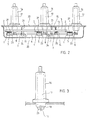
- the basic components of a circuit breaker according to the invention are moving contacts 1 intended for each phase of a transformer and respective fixed contacts 2 cooperating with the moving contacts.
- Ends 4 of a primary winding of the transformer are connected to the fixed contacts 2, which are fastened to a fastening rod 3 made of dielectric insulating material.
- the fastening rod 3 is fastened to frame parts 21 of the circuit breaker.
- the U-shaped moving contacts 1 are mounted on a shaft 6, parallell with the fastening rod 3 and mounted in bearings on the frame parts 21 at points 7, to allow a revolution about its axis.
- the contacts 1 are arranged to act simultaneously by means of the shaft 6, and the contact force between the contacts 1 and 2 is each time given by a spring 5 tensioned between branches 1 a and 1b of the moving contact 1. Further, because of the U-shape of the moving contacts 1, their contact force increases when the current increases, and consequently, the contact 1 endures a short circuit situation of the secondary side of the transformer and high currents caused by a fault in winding.
- the circuit breaker is immersed in a trough 20 filled with dielectric liquid, which trough guarantees the operation of the circuit breaker even though the casing (not shown in the drawings) surrounding the whole system has been leaking.
- Each primary phase comprises a high voltage fuse 17 known from the use of fuse circuit breaker, which fuse is each time integrated into a feedthrough insulator 16 fastened to a cover 22 of the casing 20 and electrically connected in series with the circuit breaker.
- the breaker mechanism comprises further at least one link-spring mechanism comprising a lug 9 fastened to the shaft 6, a tap 11 fastened to the lug with a cotter bolt 10, one end of the tap being fastened to the rod 3 by means of a support 24, and a pressure spring 12 mounted about the tap 11, which spring, in the closed position of the contacts 1 and 2, pushes slightly the breaker mechanism swung over the dead spot of turning the shaft 6 and prevents unintentional releases caused by impact or vibration.
- the dead spot of turning the shaft 6 signifies the line C shown in Figure 4 (the line between one end of the tap 11, a fastening cotter 26 of the support 24, and the axis of the shaft 6), whereby the shaft 6 swings in the opposite direction when the cotter bolt 10 crosses said line C as a result of the operation of the trip pin 19. Accordingly, when the fuse 17 is operating, the operation of its trip pin 19 turns the shaft 6 and the moving contacts 1 of all phases from the closed position towards the open position over said dead spot.
- the breaker mechanism has been supplemented with a mechanical trip mechanism, comprising tight bellows 13 containing gas.
- a mechanical trip mechanism comprising tight bellows 13 containing gas.
- the bellows 13 sink down and trip a trip pin 14, which turns by the force of the spring 15 the shaft 6 and the contacts 1 of all phases from the closed position towards the open position over the dead spot of turning said shaft described above.
- the link-spring mechanism 9 to 12 opens the circuit breaker in the same way as at a release caused by a fuse.
- Still another link-spring mechanism 9 to 12 is preferably fastened beside this arrangement, whereby these two mechanisms 9 to 12 guarantee a sufficient force for holding the connection and a sufficient force for pushing to the extreme open position in all situations.
- Temperature protections may comprise a temperature sensor arranged in connection with the circuit breaker, such as a bimetal means or a capillary provided with a trip pin.
- the protection tripping by sinking liquid surface may comprise a float also provided with a trip pin.
- an electromechanical trigger can be arranged in connection with the circuit breaker for turning the shaft 6 of the circuit breaker by electric remote control, for instance, but otherwise in the above-described manner, and thus for disconnecting the contacts 1 and 2, when there is some other specific reason for this.
- Auxiliary contact information on the state of the circuit breaker can additionally be detected by means of at least one auxiliary contact, for example to be transmitted by means of a remote control system to the operation supervisor.
- the shaft 6 of the circuit breaker can also be brought through the walls of the structures surrounding the circuit breaker, whereby it is possible to arrange a mechanical outside display of position data and a retuning of the circuit breaker from outside the transformer.
- lever arm fastened to the shaft 6 and intended for the trigger means can also be integrated into the moving contact 1.
- separate lever arms can be used for different triggers or some triggers may have a common lever arm.
Landscapes
- Breakers (AREA)
- Driving Mechanisms And Operating Circuits Of Arc-Extinguishing High-Tension Switches (AREA)
- Keying Circuit Devices (AREA)
- Fuses (AREA)
- Push-Button Switches (AREA)
- Gas-Insulated Switchgears (AREA)
- Illuminated Signs And Luminous Advertising (AREA)
- Orthopedics, Nursing, And Contraception (AREA)
- Auxiliary Devices For Music (AREA)
Claims (18)
- Schutzschalter, der in einem Fehlerfall angeordnet ist, ein elektrisches Gerät wie einen Verteilertransformator von einem Mittelspannungsnetz oder einem Hochspannungsnetz an jedem Terminal zu trennen, und welcher Schutzschalter in jeder Phase zumindest einen Festkontakt (2) und einen beweglichen Kontakt (1) aufweist, der mit dem Festkontakt zu koppeln und davon zu entkoppeln ist, wobei der Schutzschalter gleichzeitig elektrisch in Serie mit einer in jeder Phase befindlichen Hochspannungssicherung (17) geschaltet ist, wobei zumindest ein Gelenk-Feder-Mechanismus (9 bis 12) angeordnet ist, die Kontakte (1, 2) in einer Verbindungsstellung unter Spannung zu halten und sie während Trennung in die äusserste getrennte Stellung auseinander zu schieben, während die Welle (6) über den toten Punkt ihrer Drehung anhand von Auslösemitteln (18, 19) gebracht wird, dadurch gekennzeichnet, dass
jeder bewegliche Kontakt (1) an der Drehwelle (6) des Schutzschalters angeordnet ist,
die Welle (6) in jeder Phase mit einem Hebelarm (8) versehen ist, wobei jeder Hebelarm angeordnet ist, sich anhand der aus einem Auslösestift (19) und einer Schlagvorrichtung (18) der Hochspannungssicherung (17) bestehenden Auslösemittel, der gemeinsamen Welle (6) des Hebelarms (8) und des beweglichen Kontakts (1) und somit der beweglichen Kontakte (1) aller Phasen von der besagten Verbindungsstellung über den besagten toten Punkt der Drehung der besagten Welle zu drehen. - Schutzschalter nach Anspruch 1, dadurch gekennzeichnet, dass er innerhalb eines Gehäuses des elektrischen Geräts, zum Beispiel eines Tanks eines Verteilertransformators, angeordnet ist.
- Schutzschalter nach Anspruch 1 oder 2, dadurch gekennzeichnet, dass er in einer dielektrischen Flüssigkeit eingetaucht ist.
- Schutzschalter nach einem der vorhergehenden Ansprüche, dadurch gekennzeichnet, dass eine Mulde (20) um den Schutzschalter herum angeordnet ist, um den Schutzschalter in der dielektrischen Flüssigkeit zu halten.
- Schutzschalter nach einem der vorhergehenden Ansprüche, dadurch gekennzeichnet, dass eine Hochspannungssicherung (17) zumindest teilweise innerhalb eines Durchführungsisolators (16) angeordnet ist, der an der Wand des Gehäuses des elektrischen Geräts oder an einer Abdeckung (22) der Mulde (20) befestigt ist.
- Schutzschalter nach einem der vorhergehenden Ansprüche, dadurch gekennzeichnet, dass ein Ende (23) der Hochspannungssicherung (17) in jeder Phase als ein Festkontakt des Schutzschalters dient.
- Schutzschalter nach einem der vorhergehenden Ansprüche, dadurch gekennzeichnet, dass der Hebelarm (8) ein selbständiges Mittel ist.
- Schutzschalter nach einem der Ansprüche 1 bis 6, dadurch gekennzeichnet, dass der Hebelarm in einen beweglichen Kontakt integriert ist.
- Schutzschalter nach einem der vorhergehenden Ansprüche, dadurch gekennzeichnet, dass ein Balg (10) in Verbindung mit dem Schutzschalter angeordnet ist, welcher Balg mit einem Auslösestift (14) versehen ist, der angeordnet ist, die Welle (6) des Schutzschalters anhand des Hebelarms über den toten Punkt der Drehung der Welle zu drehen, wenn der Druck der dielektrischen Flüssigkeit den vorbestimmten Grenzwert überschreitet.
- Schutzschalter nach einem der vorhergehenden Ansprüche, dadurch gekennzeichnet, dass ein Bimetallmittel in Verbindung mit dem Schutzschalter angeordnet ist, welches Mittel mit einem Auslösestift versehen ist, der angeordnet ist, die Welle (6) des Schutzschalters anhand des Hebelarms über den toten Punkt der Drehung der Welle zu drehen, wenn die Temperatur der dielektrischen Flüssigkeit den vorbestimmten Grenzwert überschreitet.
- Schutzschalter nach einem der vorhergehenden Ansprüche, dadurch gekennzeichnet, dass ein Schwimmer in Verbindung mit dem Schutzschalter angeordnet ist, welcher Schwimmer mit einem Auslösestift versehen ist, der angeordnet ist, die Welle (6) des Schutzschalters anhand des Hebelarms über den toten Punkt der Drehung der Welle zu drehen, wenn der Flüssigkeitspegel unter dem vorbestimmten Wert liegt.
- Schutzschalter nach einem der vorhergehenden Ansprüche, dadurch gekennzeichnet, dass ein elektromechanischer Trigger in Verbindung mit dem Schutzschalter angeordnet ist, um die Welle (6) des Schutzschalters anhand des Hebelarms über den toten Punkt der Drehung der Welle zu drehen.
- Schutzschalter nach einem der vorhergehenden Ansprüche, dadurch gekennzeichnet, dass ein Temperatursensor, zum Beispiel ein Kapillar- oder Bimetallmittel, mit einem Trigger zusätzlich in Verbindung mit dem Schutzschalter angeordnet ist, wobei der Trigger angeordnet ist, die Welle des Schutzschalters anhand des Hebelarms über den toten Punkt der Drehung der Welle zu drehen, wenn die Temperatur der Wicklungen des elektrischen Geräts den vorbestimmten Grenzwert überschreitet.
- Schutzschalter nach einem der Ansprüche 9 bis 13, dadurch gekennzeichnet, dass der Hebelarm derselbe Hebelarm ist, der in Verbindung mit der Hochspannungssicherung ist.
- Schutzschalter nach einem der Ansprüche 9 bis 13, dadurch gekennzeichnet, dass der Hebelarm ein separater für das besagte Mittel vorgesehener Hebelarm ist.
- Schutzschalter nach einem der vorhergehenden Ansprüche, dadurch gekennzeichnet, dass der Schutzschalter mit zumindest einem zusätzlichen Kontakt zum Übertragen von Positionsdaten des Schutzschalters versehen ist.
- Schutzschalter nach einem der Ansprüche 2 bis 15, dadurch gekennzeichnet, dass sich zumindest ein Ende der Welle (6) des Schutzschalters durch die Wand des Gehäuses des elektrischen Geräts erstreckt und mit einem Stellungsanzeiger zum Detektieren der Stellung des Schutzschalters von ausserhalb des Geräts versehen ist.
- Schutzschalter nach einem der Ansprüche 2 bis 17, dadurch gekennzeichnet, dass sich zumindest ein Ende der Welle (6) des Schutzschalters durch die Wand des Gehäuses des elektrischen Geräts erstreckt, um die Einstellung des Schutzschalters in die Betriebsstellung von ausserhalb des Geräts zu ermöglichen.
Applications Claiming Priority (3)
| Application Number | Priority Date | Filing Date | Title |
|---|---|---|---|
| FI970504A FI102329B (fi) | 1997-02-06 | 1997-02-06 | Kytkin sähköisen laitteen erottamiseksi sähköverkosta |
| FI970504 | 1997-02-06 | ||
| PCT/FI1998/000103 WO1998035419A1 (en) | 1997-02-06 | 1998-02-04 | Circuit breaker for disconnecting an electrical apparatus from electrical network |
Publications (2)
| Publication Number | Publication Date |
|---|---|
| EP0958643A1 EP0958643A1 (de) | 1999-11-24 |
| EP0958643B1 true EP0958643B1 (de) | 2011-04-20 |
Family
ID=8548086
Family Applications (1)
| Application Number | Title | Priority Date | Filing Date |
|---|---|---|---|
| EP98902019A Expired - Lifetime EP0958643B1 (de) | 1997-02-06 | 1998-02-04 | Schutzschalter zum trennen eines elektrischen geräts von einem elektrischen netz |
Country Status (11)
| Country | Link |
|---|---|
| US (1) | US6479780B2 (de) |
| EP (1) | EP0958643B1 (de) |
| JP (1) | JP3727071B2 (de) |
| AT (1) | ATE506725T1 (de) |
| AU (1) | AU5868098A (de) |
| BE (1) | BE1012970A5 (de) |
| DE (1) | DE69842228D1 (de) |
| FI (1) | FI102329B (de) |
| FR (1) | FR2759212B1 (de) |
| IE (1) | IE980051A1 (de) |
| WO (1) | WO1998035419A1 (de) |
Families Citing this family (20)
| Publication number | Priority date | Publication date | Assignee | Title |
|---|---|---|---|---|
| US6628095B1 (en) * | 1998-11-10 | 2003-09-30 | Tyco Electronics Logistics A.G. | Actuator for remote operation of a circuit breaker |
| WO2003031686A2 (en) * | 2001-10-12 | 2003-04-17 | Envirosense, Llc | Cathodic protection remote monitoring method and apparatus |
| FR2831342B1 (fr) * | 2001-10-22 | 2003-12-19 | Alstom | Systeme de protection d'un transformateur de distribution triphase a isolation dans un dielectrique liquide comportant un interrupteur sectionneur de phase |
| AU2002235947A1 (en) * | 2002-02-15 | 2003-09-04 | Grupo Ormazabal, S.A. | Transmission system for tripping a fuse holder |
| US7312085B2 (en) * | 2002-04-01 | 2007-12-25 | Fluidigm Corporation | Microfluidic particle-analysis systems |
| US6971898B2 (en) * | 2003-12-11 | 2005-12-06 | Electric Power Research Institute, Inc. | Apparatus and method for electrically and mechanically connecting and disconnecting a power line |
| PT2075807E (pt) | 2007-12-28 | 2014-12-31 | Constructora De Transformadores De Distribucion Cotradis S L U | Equipamento elétrico para redes de distribuição com sistema de deteção de falhas, sistema de desligamento e de eliminação de falhas |
| US8345393B1 (en) | 2008-05-02 | 2013-01-01 | Mike Martinez | Exterior primary fuse system for transformers |
| DE102008047931A1 (de) * | 2008-09-19 | 2010-04-08 | Siemens Aktiengesellschaft | Vorrichtung zur Absicherung eines mehrphasig betriebenen elektrischen Gerätes, mechanischer Trennschalter und Betriebsverfahren |
| FR2942353B1 (fr) * | 2009-02-19 | 2011-06-17 | Transfix Toulon Sa Soc Nouv | Procede, dispositif et systeme de protection d'un appareil electrique, ainsi que transformateur et poste comportant un tel dispositif ou systeme |
| US9041402B2 (en) * | 2009-12-08 | 2015-05-26 | Eht International Inc. | Detecting an abnormality of a switch in a high voltage electrical substation |
| US8471296B2 (en) | 2011-01-21 | 2013-06-25 | International Business Machines Corporation | FinFET fuse with enhanced current crowding |
| SI24060B (sl) * | 2012-04-12 | 2017-07-31 | Razvojni Center Enem Novi Materiali D.O.O. | Stikalo za zaščito električnega tokokroga proti preobremenitvam |
| US9530576B2 (en) | 2013-04-10 | 2016-12-27 | Savannah River Nuclear Solutions, Llc | Device for remote operation of electrical disconnect |
| CN104765001A (zh) * | 2015-04-27 | 2015-07-08 | 句容华源电器设备有限公司 | 弹簧储能型断路器合闸铁心不动作故障检测方法 |
| CN107742594A (zh) * | 2017-11-08 | 2018-02-27 | 河南森源电气股份有限公司 | 一种高压柜配式断路器传动结构及其单极极柱 |
| CN109459158A (zh) * | 2018-12-27 | 2019-03-12 | 安徽中电兴发与鑫龙科技股份有限公司 | 一种在线测温型断路器及其测温方法 |
| EP3787000B1 (de) | 2019-08-29 | 2022-05-25 | Hitachi Energy Switzerland AG | Elektrische anordnung mit anzeigevorrichtung für durchgebrannte sicherung |
| KR102282679B1 (ko) * | 2021-02-03 | 2021-07-28 | (주)그린파워 | 다이렉트 전기차 충전기 |
| CN113113276B (zh) * | 2021-03-02 | 2022-11-25 | 国网冀北电力有限公司廊坊供电公司 | 可更换自启式熔断器 |
Family Cites Families (19)
| Publication number | Priority date | Publication date | Assignee | Title |
|---|---|---|---|---|
| GB270456A (en) * | 1926-03-13 | 1927-05-12 | David Reginald Davies | Improvements in or relating to circuit interrupters |
| NL66668C (de) * | 1940-05-31 | |||
| US2376789A (en) | 1942-07-24 | 1945-05-22 | Westinghouse Electric & Mfg Co | Protective device for electrical apparatus and systems |
| US3611034A (en) * | 1969-12-23 | 1971-10-05 | Westinghouse Electric Corp | Electrical transformer |
| US4006439A (en) * | 1975-09-11 | 1977-02-01 | Westinghouse Electric Corporation | Circuit interrupter having an insulated bridging contact |
| US4138602A (en) * | 1977-10-31 | 1979-02-06 | Westinghouse Electric Corp. | Over-center toggle switch |
| FR2441938A1 (fr) * | 1978-11-17 | 1980-06-13 | Merlin Gerin | Dispositif de declenchement a percuteur pour coupe-circuit a fusibles incorpores dans une cellule prefabriquee moyenne tension |
| JPS5879834U (ja) * | 1981-11-19 | 1983-05-30 | エナジーサポート株式会社 | 限流ヒユ−ズ付開閉器のヒユ−ズリンク係止装置 |
| JPS58123551U (ja) * | 1982-02-16 | 1983-08-23 | エナジーサポート株式会社 | 限流ヒユ−ズ付負荷開閉器 |
| NO152528C (no) * | 1983-04-12 | 1985-10-09 | Norsk Elektrisk & Brown Boveri | Anordning ved kompaktbryteranlegg. |
| GB8502036D0 (en) * | 1985-01-28 | 1985-02-27 | Ass Elect Ind | Interrupter/isolator |
| JPS61199849U (de) * | 1985-06-03 | 1986-12-13 | ||
| GB8518381D0 (en) * | 1985-07-20 | 1985-08-29 | Y S Securities Ltd | Circuit interrupter |
| FR2683939B1 (fr) * | 1991-11-20 | 1993-12-31 | Gec Alsthom Sa | Disjoncteur auto-sectionneur a moyenne tension et application a une cellule et a un poste a moyenne tension. |
| JPH0636655A (ja) * | 1992-07-10 | 1994-02-10 | Oogaki Denki Kk | 限流ヒューズ付高圧交流負荷開閉器 |
| JPH06260077A (ja) * | 1993-03-08 | 1994-09-16 | Hitachi Ltd | ヒューズ付開閉器 |
| FR2712730B1 (fr) | 1993-11-15 | 1995-12-29 | France Transfo Sa | Transformateur électrique imergé protégé. |
| JP3457990B2 (ja) * | 1994-03-17 | 2003-10-20 | 株式会社キューヘン | 高圧配電線の断線箇所決定方法及び装置 |
| FR2750809B1 (fr) | 1996-07-02 | 1998-10-30 | Transfix Soc Nouv | Dispositif de protection contre des effets des defauts internes d'un appareil electrique |
-
1997
- 1997-02-06 FI FI970504A patent/FI102329B/fi not_active IP Right Cessation
-
1998
- 1998-01-27 IE IE980051A patent/IE980051A1/en not_active Application Discontinuation
- 1998-02-04 AT AT98902019T patent/ATE506725T1/de not_active IP Right Cessation
- 1998-02-04 EP EP98902019A patent/EP0958643B1/de not_active Expired - Lifetime
- 1998-02-04 BE BE9800083A patent/BE1012970A5/fr active
- 1998-02-04 US US09/355,649 patent/US6479780B2/en not_active Expired - Fee Related
- 1998-02-04 AU AU58680/98A patent/AU5868098A/en not_active Abandoned
- 1998-02-04 WO PCT/FI1998/000103 patent/WO1998035419A1/en not_active Ceased
- 1998-02-04 DE DE69842228T patent/DE69842228D1/de not_active Expired - Lifetime
- 1998-02-04 JP JP53381598A patent/JP3727071B2/ja not_active Expired - Fee Related
- 1998-02-05 FR FR9801332A patent/FR2759212B1/fr not_active Expired - Fee Related
Also Published As
| Publication number | Publication date |
|---|---|
| WO1998035419A1 (en) | 1998-08-13 |
| FI102329B1 (fi) | 1998-11-13 |
| FR2759212A1 (fr) | 1998-08-07 |
| FI970504L (fi) | 1998-08-07 |
| AU5868098A (en) | 1998-08-26 |
| FR2759212B1 (fr) | 2000-12-22 |
| JP3727071B2 (ja) | 2005-12-14 |
| US20020053554A1 (en) | 2002-05-09 |
| JP2001510626A (ja) | 2001-07-31 |
| FI102329B (fi) | 1998-11-13 |
| EP0958643A1 (de) | 1999-11-24 |
| IE980051A1 (en) | 1998-08-12 |
| ATE506725T1 (de) | 2011-05-15 |
| FI970504A0 (fi) | 1997-02-06 |
| DE69842228D1 (de) | 2011-06-01 |
| BE1012970A5 (fr) | 2001-07-03 |
| US6479780B2 (en) | 2002-11-12 |
Similar Documents
| Publication | Publication Date | Title |
|---|---|---|
| EP0958643B1 (de) | Schutzschalter zum trennen eines elektrischen geräts von einem elektrischen netz | |
| EP0093076A2 (de) | Primärschutzschalter | |
| US4660009A (en) | Modular integral circuit interrupter | |
| US3983454A (en) | Distribution transformer secondary circuit breaker | |
| AU753147B2 (en) | Immersed transformer self-protected by a device including a circuit breaker and fuses | |
| KR101588486B1 (ko) | 저동력 저오일 트립 메커니즘 | |
| US4323871A (en) | Circuit protecting apparatus including resettable vacuum fuse and switch | |
| US4336520A (en) | Method and apparatus for short circuit protection of high voltage distribution systems | |
| US3365616A (en) | Overvoltage protection system for electrical apparatus with current limiting fuse and removable oil fuse in series on line side | |
| SE538536C2 (sv) | Anordning för skydd av en elektrisk apparat som matas av ettflerfasnät | |
| US3009035A (en) | Circuit interrupters | |
| US2066935A (en) | Surge and outageproof distribution transformer | |
| US4442471A (en) | Method and apparatus for short circuit protection of high voltage distribution systems | |
| NO302988B1 (no) | Koblingsinnretning med en lastbryter eller lastskillebryter og en sikring | |
| US2457939A (en) | High-voltage switch | |
| US4617545A (en) | Submersible primary circuit breaker | |
| EP2075807B1 (de) | Elektrische Vorrichtung für ein Verteilungsnetzwerk mit Fehlererkennung, Abschalt- und Entfernungssystem | |
| US4324961A (en) | Distribution transformer having a primary disconnect switch | |
| CA1214507A (en) | Secondary circuit breaker for distribution transformer | |
| US4521823A (en) | Submersible primary circuit breaker | |
| Fulchiron | Protection of MV/LV substation transformers | |
| US4363063A (en) | Load break switch with built-in ground fault sensing | |
| US20250246383A1 (en) | Interrupter with inverted configuration and self-unlatching mechanism | |
| Blower et al. | Trends in distribution transformer protection | |
| US1921005A (en) | Electric oil cut-out |
Legal Events
| Date | Code | Title | Description |
|---|---|---|---|
| PUAI | Public reference made under article 153(3) epc to a published international application that has entered the european phase |
Free format text: ORIGINAL CODE: 0009012 |
|
| 17P | Request for examination filed |
Effective date: 19990723 |
|
| AK | Designated contracting states |
Kind code of ref document: A1 Designated state(s): AT CH DE DK ES FI GB GR IT LI LU MC NL PT SE |
|
| 17Q | First examination report despatched |
Effective date: 20071011 |
|
| GRAP | Despatch of communication of intention to grant a patent |
Free format text: ORIGINAL CODE: EPIDOSNIGR1 |
|
| GRAS | Grant fee paid |
Free format text: ORIGINAL CODE: EPIDOSNIGR3 |
|
| GRAA | (expected) grant |
Free format text: ORIGINAL CODE: 0009210 |
|
| RAP1 | Party data changed (applicant data changed or rights of an application transferred) |
Owner name: ABB OY |
|
| AK | Designated contracting states |
Kind code of ref document: B1 Designated state(s): AT CH DE DK ES FI GB GR IT LI LU MC NL PT SE |
|
| REG | Reference to a national code |
Ref country code: GB Ref legal event code: FG4D |
|
| REG | Reference to a national code |
Ref country code: CH Ref legal event code: EP |
|
| REF | Corresponds to: |
Ref document number: 69842228 Country of ref document: DE Date of ref document: 20110601 Kind code of ref document: P |
|
| REG | Reference to a national code |
Ref country code: DE Ref legal event code: R096 Ref document number: 69842228 Country of ref document: DE Effective date: 20110601 |
|
| REG | Reference to a national code |
Ref country code: SE Ref legal event code: TRGR |
|
| REG | Reference to a national code |
Ref country code: NL Ref legal event code: VDEP Effective date: 20110420 |
|
| PG25 | Lapsed in a contracting state [announced via postgrant information from national office to epo] |
Ref country code: PT Free format text: LAPSE BECAUSE OF FAILURE TO SUBMIT A TRANSLATION OF THE DESCRIPTION OR TO PAY THE FEE WITHIN THE PRESCRIBED TIME-LIMIT Effective date: 20110822 |
|
| PG25 | Lapsed in a contracting state [announced via postgrant information from national office to epo] |
Ref country code: AT Free format text: LAPSE BECAUSE OF FAILURE TO SUBMIT A TRANSLATION OF THE DESCRIPTION OR TO PAY THE FEE WITHIN THE PRESCRIBED TIME-LIMIT Effective date: 20110420 Ref country code: ES Free format text: LAPSE BECAUSE OF FAILURE TO SUBMIT A TRANSLATION OF THE DESCRIPTION OR TO PAY THE FEE WITHIN THE PRESCRIBED TIME-LIMIT Effective date: 20110731 Ref country code: FI Free format text: LAPSE BECAUSE OF FAILURE TO SUBMIT A TRANSLATION OF THE DESCRIPTION OR TO PAY THE FEE WITHIN THE PRESCRIBED TIME-LIMIT Effective date: 20110420 Ref country code: GR Free format text: LAPSE BECAUSE OF FAILURE TO SUBMIT A TRANSLATION OF THE DESCRIPTION OR TO PAY THE FEE WITHIN THE PRESCRIBED TIME-LIMIT Effective date: 20110721 |
|
| PG25 | Lapsed in a contracting state [announced via postgrant information from national office to epo] |
Ref country code: NL Free format text: LAPSE BECAUSE OF FAILURE TO SUBMIT A TRANSLATION OF THE DESCRIPTION OR TO PAY THE FEE WITHIN THE PRESCRIBED TIME-LIMIT Effective date: 20110420 |
|
| PLBE | No opposition filed within time limit |
Free format text: ORIGINAL CODE: 0009261 |
|
| STAA | Information on the status of an ep patent application or granted ep patent |
Free format text: STATUS: NO OPPOSITION FILED WITHIN TIME LIMIT |
|
| PG25 | Lapsed in a contracting state [announced via postgrant information from national office to epo] |
Ref country code: DK Free format text: LAPSE BECAUSE OF FAILURE TO SUBMIT A TRANSLATION OF THE DESCRIPTION OR TO PAY THE FEE WITHIN THE PRESCRIBED TIME-LIMIT Effective date: 20110420 |
|
| 26N | No opposition filed |
Effective date: 20120123 |
|
| REG | Reference to a national code |
Ref country code: DE Ref legal event code: R097 Ref document number: 69842228 Country of ref document: DE Effective date: 20120123 |
|
| PG25 | Lapsed in a contracting state [announced via postgrant information from national office to epo] |
Ref country code: IT Free format text: LAPSE BECAUSE OF FAILURE TO SUBMIT A TRANSLATION OF THE DESCRIPTION OR TO PAY THE FEE WITHIN THE PRESCRIBED TIME-LIMIT Effective date: 20110420 |
|
| PG25 | Lapsed in a contracting state [announced via postgrant information from national office to epo] |
Ref country code: MC Free format text: LAPSE BECAUSE OF NON-PAYMENT OF DUE FEES Effective date: 20120229 |
|
| REG | Reference to a national code |
Ref country code: CH Ref legal event code: PL |
|
| GBPC | Gb: european patent ceased through non-payment of renewal fee |
Effective date: 20120204 |
|
| PG25 | Lapsed in a contracting state [announced via postgrant information from national office to epo] |
Ref country code: CH Free format text: LAPSE BECAUSE OF NON-PAYMENT OF DUE FEES Effective date: 20120229 Ref country code: LI Free format text: LAPSE BECAUSE OF NON-PAYMENT OF DUE FEES Effective date: 20120229 |
|
| PG25 | Lapsed in a contracting state [announced via postgrant information from national office to epo] |
Ref country code: GB Free format text: LAPSE BECAUSE OF NON-PAYMENT OF DUE FEES Effective date: 20120204 |
|
| PG25 | Lapsed in a contracting state [announced via postgrant information from national office to epo] |
Ref country code: LU Free format text: LAPSE BECAUSE OF NON-PAYMENT OF DUE FEES Effective date: 20120204 |
|
| PGFP | Annual fee paid to national office [announced via postgrant information from national office to epo] |
Ref country code: DE Payment date: 20150219 Year of fee payment: 18 |
|
| PGFP | Annual fee paid to national office [announced via postgrant information from national office to epo] |
Ref country code: SE Payment date: 20150218 Year of fee payment: 18 |
|
| REG | Reference to a national code |
Ref country code: DE Ref legal event code: R119 Ref document number: 69842228 Country of ref document: DE |
|
| REG | Reference to a national code |
Ref country code: SE Ref legal event code: EUG |
|
| PG25 | Lapsed in a contracting state [announced via postgrant information from national office to epo] |
Ref country code: SE Free format text: LAPSE BECAUSE OF NON-PAYMENT OF DUE FEES Effective date: 20160205 |
|
| PG25 | Lapsed in a contracting state [announced via postgrant information from national office to epo] |
Ref country code: DE Free format text: LAPSE BECAUSE OF NON-PAYMENT OF DUE FEES Effective date: 20160901 |