EP0959184B1 - Verfahren zum Aufbereiten von Bodenaushub - Google Patents
Verfahren zum Aufbereiten von Bodenaushub Download PDFInfo
- Publication number
- EP0959184B1 EP0959184B1 EP99106406A EP99106406A EP0959184B1 EP 0959184 B1 EP0959184 B1 EP 0959184B1 EP 99106406 A EP99106406 A EP 99106406A EP 99106406 A EP99106406 A EP 99106406A EP 0959184 B1 EP0959184 B1 EP 0959184B1
- Authority
- EP
- European Patent Office
- Prior art keywords
- bin
- aggregate
- excavator
- excavated material
- silo
- Prior art date
- Legal status (The legal status is an assumption and is not a legal conclusion. Google has not performed a legal analysis and makes no representation as to the accuracy of the status listed.)
- Expired - Lifetime
Links
- 239000000463 material Substances 0.000 title claims abstract description 30
- 238000004519 manufacturing process Methods 0.000 title claims description 3
- 239000000203 mixture Substances 0.000 claims abstract description 15
- 238000000034 method Methods 0.000 claims description 16
- 238000003892 spreading Methods 0.000 claims description 8
- 229910000831 Steel Inorganic materials 0.000 claims description 2
- 239000010959 steel Substances 0.000 claims description 2
- 239000000654 additive Substances 0.000 abstract description 9
- 230000000996 additive effect Effects 0.000 abstract description 4
- 239000002689 soil Substances 0.000 description 10
- 238000010276 construction Methods 0.000 description 8
- 238000009412 basement excavation Methods 0.000 description 6
- 239000011230 binding agent Substances 0.000 description 4
- 239000003381 stabilizer Substances 0.000 description 4
- 239000004568 cement Substances 0.000 description 2
- 239000011798 excavation material Substances 0.000 description 2
- 238000003801 milling Methods 0.000 description 2
- 230000006641 stabilisation Effects 0.000 description 2
- 238000011105 stabilization Methods 0.000 description 2
- 235000008733 Citrus aurantifolia Nutrition 0.000 description 1
- 241001140714 Citrus latifolia Species 0.000 description 1
- 241000196324 Embryophyta Species 0.000 description 1
- 235000011941 Tilia x europaea Nutrition 0.000 description 1
- 238000004026 adhesive bonding Methods 0.000 description 1
- 238000006243 chemical reaction Methods 0.000 description 1
- 239000000428 dust Substances 0.000 description 1
- 230000007613 environmental effect Effects 0.000 description 1
- 238000001704 evaporation Methods 0.000 description 1
- 230000008020 evaporation Effects 0.000 description 1
- 238000009434 installation Methods 0.000 description 1
- 239000004571 lime Substances 0.000 description 1
- XLYOFNOQVPJJNP-UHFFFAOYSA-N water Substances O XLYOFNOQVPJJNP-UHFFFAOYSA-N 0.000 description 1
Images


Classifications
-
- E—FIXED CONSTRUCTIONS
- E02—HYDRAULIC ENGINEERING; FOUNDATIONS; SOIL SHIFTING
- E02F—DREDGING; SOIL-SHIFTING
- E02F5/00—Dredgers or soil-shifting machines for special purposes
-
- E—FIXED CONSTRUCTIONS
- E02—HYDRAULIC ENGINEERING; FOUNDATIONS; SOIL SHIFTING
- E02F—DREDGING; SOIL-SHIFTING
- E02F3/00—Dredgers; Soil-shifting machines
- E02F3/04—Dredgers; Soil-shifting machines mechanically-driven
- E02F3/96—Dredgers; Soil-shifting machines mechanically-driven with arrangements for alternate or simultaneous use of different digging elements
- E02F3/963—Arrangements on backhoes for alternate use of different tools
-
- E—FIXED CONSTRUCTIONS
- E02—HYDRAULIC ENGINEERING; FOUNDATIONS; SOIL SHIFTING
- E02F—DREDGING; SOIL-SHIFTING
- E02F5/00—Dredgers or soil-shifting machines for special purposes
- E02F5/22—Dredgers or soil-shifting machines for special purposes for making embankments; for back-filling
- E02F5/223—Dredgers or soil-shifting machines for special purposes for making embankments; for back-filling for back-filling
Definitions
- the invention relates to a method for preparing excavated soil with admixture of additives.
- Soil stabilization system BSS in which the excavation of a Trench or canal next to or in the trench or canal a stabilizing agent such as lime, cement or the like is mixed. This is done on the excavated material that is either next to the trench or already again brought into the trench by an excavator in a first layer has been applied, the stabilizing agent. This is followed by mixing the stabilizing agent excavation by using a loader to which a milling machine is attached over the excavation material covered with stabilizing agent is driven away. After mixing, the excavated material, provided the mixing is not already in the trench took place in the trench with an excavator and compacted again before the next layer of excavated material is mixed with binder.
- a stabilizing agent such as lime, cement or the like
- the invention has for its object a method for processing by digging soil to make it more economical can be carried out.
- This new method can also be used in confined spaces be carried out comfortably. Even with smaller quantities the technical effort and costs are cheaper Relationship than ever since.
- the invention also relates to a silo for receiving and Spreading pourable materials, especially of Additives for processing soil excavation accordingly the method of claim 1 with a motor-driven Conveyor for material discharge, the Silo to the pickup arm of an excavator, preferably can be mounted by means of a quick-change device.
- a silo for receiving and Spreading pourable materials, especially of Additives for processing soil excavation accordingly the method of claim 1 with a motor-driven Conveyor for material discharge, the Silo to the pickup arm of an excavator, preferably can be mounted by means of a quick-change device. This makes the silo even in tight construction site conditions easy and convenient to use. With spatial changes You can react flexibly on the construction site.
- the Drive the conveyor be a hydraulic motor, the controllable by the hydraulic control of the excavator is. In this way, the conveyor to the hydraulic system of the excavator and conveniently operated from the excavator cab become.
- the silo can have a dispersing device.
- the silo can have a closable opening for filling.
- silo against the rough environmental conditions on the Construction site it can be made of steel.
- Fig. 1 shows a silo 10, which on a receptacle 11 for a Excavator 12 added becomes.
- FIG. 2 shows the silo 10 as it is from a stationary silo 20 via its conveyor 21 with an additive 22 or aggregate mixture is filled.
- Fig. 3 shows how the aggregate 22 or the aggregate mixture from the silo 10 to a conveyor 31 Excavated material hill 32 coming from a trench 33 is scattered.
- FIG 4 shows the excavator 12 after the silo 10 has been replaced against a blade separator 40, which acts as a blade mixer is used.
- FIG. 5 shows the blade separator used as a blade mixer 40, which is sprinkled onto the excavated material 32 in FIG. 3 Aggregate 22 together with the excavated material 32 receives.
- the blade separator 40 mixes the aggregate 22 with the excavated material 32 by means of separator shafts 50.
- the mixing process simultaneously mixes everything Material 51 introduced into a pit 52.
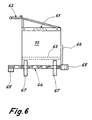
- Fig. 6 shows a side view of the silo 10, which is for receiving of aggregate 22 or aggregate mixture is used.
- the additive 22 can enter the silo 60 via an opening 61 be filled in.
- the silo 60 can be be mounted on an excavator.
- a hydraulic motor 65 connected via hydraulic lines 66 connected to the hydraulic system of the excavator drives the conveyor 64. If the silo 10 just is not in use, it can be placed on supports 67.
Landscapes
- Engineering & Computer Science (AREA)
- Mining & Mineral Resources (AREA)
- Mechanical Engineering (AREA)
- Civil Engineering (AREA)
- General Engineering & Computer Science (AREA)
- Structural Engineering (AREA)
- Preparation Of Clay, And Manufacture Of Mixtures Containing Clay Or Cement (AREA)
- Consolidation Of Soil By Introduction Of Solidifying Substances Into Soil (AREA)
- Excavating Of Shafts Or Tunnels (AREA)
- Earth Drilling (AREA)
Description
- Fig. 1
- eine schematische Darstellung der Aufnahme eines Silos durch einen Bagger;
- Fig. 2
- eine schematische Darstellung des Befüllens des Silos aus Fig. 1;
- Fig. 3
- eine schematische Darstellung des Ausstreuens des Inhalts des Silos aus Fig. 1;
- Fig. 4
- eine Seitenansicht auf einen Bagger mit einem Schaufelseparator;
- Fig. 5
- eine schematische Darstellung des Befüllens eines Grabens mit Hilfe des Schaufelseparators aus Fig. 4;
- Fig. 6
- eine Seitenansicht auf das Silo aus Fig. 1.
Claims (8)
- Verfahren zum Aufbereiten von Bodenaushub (32) unter Beimischung von Zuschlagstoffen (22), gekennzeichnet durch die Schritte:a) ein transportables mit einem Zuschlagstoff (22) oder Zuschlagstoffgemisch gefülltes Silo (10) mit einem Bagger (12) aufnehmen,b) das gefüllte Silo (10) über Aushubmaterial (32) halten und den Zuschlagstoff (22) oder das Zuschlagstoffgemisch ausstreuen,c) das Silo (10) vom Bagger (12) abbauen und einen Schaufelmischer, für dessen Funktion vorzugsweise ein Schaufelseparator (40) verwendet wird, anbauen,d) das Aushubmaterial (32) mit dem Schaufelmischer (40) aufnehmen, mischen und an einer gewünschten Stelle, beispielsweise in einen Rohrgraben (52), einbringen.
- Verfahren nach Anspruch 1, dadurch gekennzeichnet, dass nach dem Ausstreuen des Zuschlagstoffs (22) oder des Zuschlagstoffgemisches weiteres Aushubmaterial (32) auf den Zuschlagstoff (2) oder das Zuschlagstoffgemisch gegeben wird.
- Silo (10) zum Aufnehmen und Ausstreuen von schüttfähigem Material, insbesondere von Zuschlagstoffen (22) für eine Aufbereitung von Bodenaushub (32) nach einem Verfahren nach Anspruch 1, mit einer motorisch angetriebenen Fördereinrichtung (64) zum Materialaustrag, dadurch gekennzeichnet, dass es an die Aufnahme (62, 63) des Löffelstiels eines Baggers (12), vorzugsweise mittels einer Schnellwechseleinrichtung, montierbar ist.
- Silo (10) nach Anspruch 3, dadurch gekennzeichnet, dass der Antrieb der Fördereinrichtung (64) ein Hydraulikmotor (65) ist, der durch die Hydrauliksteuerung des Baggers (12) oder Laders (14) steuerbar ist.
- Silo (10) nach Anspruch 3 oder 4, dadurch gekennzeichnet, dass es eine Zerstreuvorrichtung (65) aufweist.
- Silo (10) nach einem der Ansprüche 3 bis 5, dadurch gekennzeichnet, dass es an seiner Unterseite Fußstützen (67) aufweist.
- Silo (10) nach einem der Ansprüche 3 bis 6, dadurch gekennzeichnet, dass es eine verschließbare Öffnung (61) zum Befüllen aufweist.
- Silo (10) nach einem der Ansprüche 3 bis 7, dadurch gekennzeichnet, dass es aus Stahl gefertigt ist.
Applications Claiming Priority (2)
| Application Number | Priority Date | Filing Date | Title |
|---|---|---|---|
| DE19822325A DE19822325A1 (de) | 1998-05-19 | 1998-05-19 | Verfahren zum Aufbereiten von Bodenaushub |
| DE19822325 | 1998-05-19 |
Publications (3)
| Publication Number | Publication Date |
|---|---|
| EP0959184A2 EP0959184A2 (de) | 1999-11-24 |
| EP0959184A3 EP0959184A3 (de) | 2000-08-23 |
| EP0959184B1 true EP0959184B1 (de) | 2004-04-14 |
Family
ID=7868210
Family Applications (1)
| Application Number | Title | Priority Date | Filing Date |
|---|---|---|---|
| EP99106406A Expired - Lifetime EP0959184B1 (de) | 1998-05-19 | 1999-03-27 | Verfahren zum Aufbereiten von Bodenaushub |
Country Status (3)
| Country | Link |
|---|---|
| EP (1) | EP0959184B1 (de) |
| AT (1) | ATE264434T1 (de) |
| DE (2) | DE19822325A1 (de) |
Families Citing this family (1)
| Publication number | Priority date | Publication date | Assignee | Title |
|---|---|---|---|---|
| DE10226232A1 (de) * | 2002-06-13 | 2004-01-15 | Ernst Josef Kronenberger | Verfahren zur Aufbereitung von Aushubmassen und Herstellen eines Bodenbaustoffes |
Citations (3)
| Publication number | Priority date | Publication date | Assignee | Title |
|---|---|---|---|---|
| WO1997015734A1 (en) * | 1994-07-25 | 1997-05-01 | Ballew, Raymond, E. | Pipeline padding apparatus |
| EP0798420A1 (de) * | 1996-03-29 | 1997-10-01 | Tiberio Vaccaro | Multifunktions kombinierte Baggerschaufel zum Mischen und Sieben |
| JPH10121506A (ja) * | 1996-10-23 | 1998-05-12 | Jinichiro Negishi | 浚渫用ゲート付土石類分離機 |
Family Cites Families (8)
| Publication number | Priority date | Publication date | Assignee | Title |
|---|---|---|---|---|
| FR2484664A1 (fr) * | 1980-06-12 | 1981-12-18 | Bec Freres Sa | Procede, installations et engins mobiles pour melanger en continu des adjuvants a des materiau de remblai dans des proportions constantes |
| FI86320C (fi) * | 1990-05-18 | 1992-09-02 | Risto Nyberg | Anordning foer behandling av jordmaterial. |
| US5379534A (en) * | 1991-01-22 | 1995-01-10 | Negishi; Jinichiro | Bucket equipped with mixing device, excavation machine having the bucket, and soil improvement method using the excavation machine |
| WO1993001365A1 (en) * | 1991-07-03 | 1993-01-21 | Michael John Jonson | Bucket for earth moving equipment |
| SE506398C2 (sv) * | 1993-04-16 | 1997-12-08 | Scooper Ab | Kombiskopa för upptagning och sönderdelning av material |
| US5592760A (en) * | 1995-07-25 | 1997-01-14 | Kohout; Darryl A. | Labor-saving materials dispenser |
| DE19612074C2 (de) * | 1996-03-27 | 1999-01-21 | Moebius Josef Bau | Mobile Vorrichtung zur Verbesserung von Bodenmaterial |
| DE19627465C2 (de) * | 1996-07-08 | 1997-08-07 | Uhrig Strasen Und Tiefbau Gmbh | Verfahren zum Aufbereiten von Aushubmaterial |
-
1998
- 1998-05-19 DE DE19822325A patent/DE19822325A1/de not_active Withdrawn
-
1999
- 1999-03-27 AT AT99106406T patent/ATE264434T1/de active
- 1999-03-27 EP EP99106406A patent/EP0959184B1/de not_active Expired - Lifetime
- 1999-03-27 DE DE59909144T patent/DE59909144D1/de not_active Expired - Lifetime
Patent Citations (3)
| Publication number | Priority date | Publication date | Assignee | Title |
|---|---|---|---|---|
| WO1997015734A1 (en) * | 1994-07-25 | 1997-05-01 | Ballew, Raymond, E. | Pipeline padding apparatus |
| EP0798420A1 (de) * | 1996-03-29 | 1997-10-01 | Tiberio Vaccaro | Multifunktions kombinierte Baggerschaufel zum Mischen und Sieben |
| JPH10121506A (ja) * | 1996-10-23 | 1998-05-12 | Jinichiro Negishi | 浚渫用ゲート付土石類分離機 |
Non-Patent Citations (2)
| Title |
|---|
| "Prospektbl{tter STEHR Spezialmaschinen Bodenstabilisierung", PROSPEKT STEHR, XX, XX, 1 January 1996 (1996-01-01), XX, XP002954219 * |
| Prospekt Stehr Spezialmaschinen Kalkstreuer SKS100 (Kalkverteilerschaufel) * |
Also Published As
| Publication number | Publication date |
|---|---|
| ATE264434T1 (de) | 2004-04-15 |
| DE59909144D1 (de) | 2004-05-19 |
| EP0959184A3 (de) | 2000-08-23 |
| DE19822325A1 (de) | 1999-12-09 |
| EP0959184A2 (de) | 1999-11-24 |
Similar Documents
| Publication | Publication Date | Title |
|---|---|---|
| DE69819999T2 (de) | Verfahren zum Mischen von Bodenmaterialien | |
| DE60106267T2 (de) | Recyclat und anlage zum mischen | |
| DE3603675A1 (de) | Als erdbewegungsgeraet ausgebildete kombination von einer fraese und einem behaelter | |
| US5379534A (en) | Bucket equipped with mixing device, excavation machine having the bucket, and soil improvement method using the excavation machine | |
| EP1012409B1 (de) | Vorrichtung sowie verfahren zum ausheben und auffüllen von erdreich | |
| DE102008016673A1 (de) | Vorrichtung zum Fräsen und Mischen von Böden | |
| US5491914A (en) | Bucket equipped with mixing device, excavation machine having the bucket, and soil improvement method using the excavation machine | |
| DE19627465C2 (de) | Verfahren zum Aufbereiten von Aushubmaterial | |
| WO2004101156A1 (de) | Verfahren und vorrichtung zum aufbereiten von aushub | |
| EP0959184B1 (de) | Verfahren zum Aufbereiten von Bodenaushub | |
| DE102016002644A1 (de) | Hydraulisch angetriebener Zwangsmischer | |
| DE19950435C1 (de) | Vorrichtung zum Aufbereiten von Aushubmaterial | |
| DE4206994C2 (de) | Verfahren und Vorrichtung zur Stabilisierung beschädigter Straßendecken | |
| EP0891305B1 (de) | Verfahren und vorrichtung zur verfestigung von grossen mengen pastöser massen | |
| JP6004252B2 (ja) | 土壌表層の剥ぎ取り収集工法及びバケット | |
| WO2005108325A1 (de) | Trockengemisch | |
| DE20021092U1 (de) | Vorrichtung zur Einbringung von Materialien in den Erdboden | |
| DE102008050175B4 (de) | Verfahren zur Herstellung eines temporär fließfähigen Verfüllbaustoffs, insbesondere für den Einbau in Ausschachtungen | |
| EP2050517B1 (de) | Verfahren zum Aufbereiten von kontaminiertem mineralischen Gewässersediment- oder Bodenmaterial | |
| DE102005056568A1 (de) | Trockengemisch | |
| DE4105595A1 (de) | Meliorationsverfahren zur begruendbarkeit von nutzwaeldern auf schwefelsauren tagebaukippen | |
| DE19625590C2 (de) | Einrichtung zum Verfüllen von Baugruben, Rohrgräben, Kabelgräben oder dgl. | |
| JPS5873694A (ja) | 土圧系シ−ルド掘削機における排土改良方法およびその装置 | |
| DE19931777B4 (de) | Vibrationsschaufel | |
| DE10038010A1 (de) | Vorrichtung zur Aufbereitung von Erdstoffen |
Legal Events
| Date | Code | Title | Description |
|---|---|---|---|
| PUAI | Public reference made under article 153(3) epc to a published international application that has entered the european phase |
Free format text: ORIGINAL CODE: 0009012 |
|
| AK | Designated contracting states |
Kind code of ref document: A2 Designated state(s): AT BE CH DE DK FI FR GB IE IT LI NL SE |
|
| AX | Request for extension of the european patent |
Free format text: AL;LT;LV;MK;RO;SI |
|
| PUAL | Search report despatched |
Free format text: ORIGINAL CODE: 0009013 |
|
| AK | Designated contracting states |
Kind code of ref document: A3 Designated state(s): AT BE CH CY DE DK ES FI FR GB GR IE IT LI LU MC NL PT SE |
|
| AX | Request for extension of the european patent |
Free format text: AL;LT;LV;MK;RO;SI |
|
| 17P | Request for examination filed |
Effective date: 20001220 |
|
| AKX | Designation fees paid |
Free format text: AT BE CH DE DK FI FR GB IE IT LI NL SE |
|
| TPAD | Observations filed by third parties |
Free format text: ORIGINAL CODE: EPIDOS TIPA |
|
| 17Q | First examination report despatched |
Effective date: 20030319 |
|
| GRAP | Despatch of communication of intention to grant a patent |
Free format text: ORIGINAL CODE: EPIDOSNIGR1 |
|
| GRAS | Grant fee paid |
Free format text: ORIGINAL CODE: EPIDOSNIGR3 |
|
| RBV | Designated contracting states (corrected) |
Designated state(s): AT BE CH DE FI FR GB LI |
|
| GRAA | (expected) grant |
Free format text: ORIGINAL CODE: 0009210 |
|
| AK | Designated contracting states |
Kind code of ref document: B1 Designated state(s): AT BE CH DE FI FR GB LI |
|
| REG | Reference to a national code |
Ref country code: GB Ref legal event code: FG4D Free format text: NOT ENGLISH |
|
| REG | Reference to a national code |
Ref country code: CH Ref legal event code: NV Representative=s name: ROTTMANN, ZIMMERMANN + PARTNER AG Ref country code: CH Ref legal event code: EP |
|
| REF | Corresponds to: |
Ref document number: 59909144 Country of ref document: DE Date of ref document: 20040519 Kind code of ref document: P |
|
| REG | Reference to a national code |
Ref country code: IE Ref legal event code: FG4D Free format text: GERMAN |
|
| GBT | Gb: translation of ep patent filed (gb section 77(6)(a)/1977) |
Effective date: 20040621 |
|
| REG | Reference to a national code |
Ref country code: IE Ref legal event code: FD4D |
|
| ET | Fr: translation filed | ||
| PLBE | No opposition filed within time limit |
Free format text: ORIGINAL CODE: 0009261 |
|
| STAA | Information on the status of an ep patent application or granted ep patent |
Free format text: STATUS: NO OPPOSITION FILED WITHIN TIME LIMIT |
|
| 26N | No opposition filed |
Effective date: 20050117 |
|
| PGFP | Annual fee paid to national office [announced via postgrant information from national office to epo] |
Ref country code: BE Payment date: 20100323 Year of fee payment: 12 |
|
| PGFP | Annual fee paid to national office [announced via postgrant information from national office to epo] |
Ref country code: FI Payment date: 20110323 Year of fee payment: 13 |
|
| PGFP | Annual fee paid to national office [announced via postgrant information from national office to epo] |
Ref country code: GB Payment date: 20110204 Year of fee payment: 13 |
|
| REG | Reference to a national code |
Ref country code: CH Ref legal event code: PFA Owner name: RAINER SCHRODE GMBH Free format text: RAINER SCHRODE GMBH#KREUZGASSE 15#88529 ZWIEFALTEN (DE) -TRANSFER TO- RAINER SCHRODE GMBH#KREUZGASSE 15#88529 ZWIEFALTEN (DE) |
|
| BERE | Be: lapsed |
Owner name: RAINER *SCHRODE G.M.B.H. Effective date: 20110331 |
|
| REG | Reference to a national code |
Ref country code: DE Ref legal event code: R409 Ref document number: 59909144 Country of ref document: DE |
|
| PG25 | Lapsed in a contracting state [announced via postgrant information from national office to epo] |
Ref country code: BE Free format text: LAPSE BECAUSE OF NON-PAYMENT OF DUE FEES Effective date: 20110331 |
|
| PG25 | Lapsed in a contracting state [announced via postgrant information from national office to epo] |
Ref country code: DE Free format text: LAPSE BECAUSE OF NON-PAYMENT OF DUE FEES Effective date: 20111001 |
|
| REG | Reference to a national code |
Ref country code: DE Ref legal event code: R119 Ref document number: 59909144 Country of ref document: DE Effective date: 20111001 |
|
| PGFP | Annual fee paid to national office [announced via postgrant information from national office to epo] |
Ref country code: FR Payment date: 20120403 Year of fee payment: 14 |
|
| REG | Reference to a national code |
Ref country code: DE Ref legal event code: R409 Ref document number: 59909144 Country of ref document: DE |
|
| PG25 | Lapsed in a contracting state [announced via postgrant information from national office to epo] |
Ref country code: FI Free format text: LAPSE BECAUSE OF NON-PAYMENT OF DUE FEES Effective date: 20120327 |
|
| PGRI | Patent reinstated in contracting state [announced from national office to epo] |
Ref country code: DE Effective date: 20120716 |
|
| GBPC | Gb: european patent ceased through non-payment of renewal fee |
Effective date: 20120327 |
|
| PG25 | Lapsed in a contracting state [announced via postgrant information from national office to epo] |
Ref country code: GB Free format text: LAPSE BECAUSE OF NON-PAYMENT OF DUE FEES Effective date: 20120327 |
|
| PGFP | Annual fee paid to national office [announced via postgrant information from national office to epo] |
Ref country code: AT Payment date: 20120321 Year of fee payment: 14 |
|
| PGFP | Annual fee paid to national office [announced via postgrant information from national office to epo] |
Ref country code: CH Payment date: 20130319 Year of fee payment: 15 |
|
| REG | Reference to a national code |
Ref country code: DE Ref legal event code: R082 Ref document number: 59909144 Country of ref document: DE Representative=s name: DREISS PATENTANWAELTE PARTNERSCHAFT, DE |
|
| REG | Reference to a national code |
Ref country code: AT Ref legal event code: MM01 Ref document number: 264434 Country of ref document: AT Kind code of ref document: T Effective date: 20130327 |
|
| REG | Reference to a national code |
Ref country code: DE Ref legal event code: R082 Ref document number: 59909144 Country of ref document: DE Representative=s name: DREISS PATENTANWAELTE PARTG MBB, DE Effective date: 20131016 Ref country code: DE Ref legal event code: R082 Ref document number: 59909144 Country of ref document: DE Representative=s name: DREISS PATENTANWAELTE PARTNERSCHAFT, DE Effective date: 20131016 Ref country code: DE Ref legal event code: R081 Ref document number: 59909144 Country of ref document: DE Owner name: MTS MASCHINENTECHNIK SCHRODE AG, DE Free format text: FORMER OWNER: MTS GESELLSCHAFT FUER MASCHINENTECHNIK UND SONDERBAUTEN MBH, 72534 HAYINGEN, DE Effective date: 20131016 |
|
| REG | Reference to a national code |
Ref country code: FR Ref legal event code: ST Effective date: 20131129 |
|
| PG25 | Lapsed in a contracting state [announced via postgrant information from national office to epo] |
Ref country code: AT Free format text: LAPSE BECAUSE OF NON-PAYMENT OF DUE FEES Effective date: 20130327 Ref country code: FR Free format text: LAPSE BECAUSE OF NON-PAYMENT OF DUE FEES Effective date: 20130402 |
|
| REG | Reference to a national code |
Ref country code: CH Ref legal event code: PL |
|
| PG25 | Lapsed in a contracting state [announced via postgrant information from national office to epo] |
Ref country code: LI Free format text: LAPSE BECAUSE OF NON-PAYMENT OF DUE FEES Effective date: 20140331 Ref country code: CH Free format text: LAPSE BECAUSE OF NON-PAYMENT OF DUE FEES Effective date: 20140331 |
|
| PGFP | Annual fee paid to national office [announced via postgrant information from national office to epo] |
Ref country code: DE Payment date: 20180522 Year of fee payment: 20 |
|
| REG | Reference to a national code |
Ref country code: DE Ref legal event code: R071 Ref document number: 59909144 Country of ref document: DE |