EP0959200A1 - Dispositif pour l'alignement d'éléments de construction - Google Patents
Dispositif pour l'alignement d'éléments de construction Download PDFInfo
- Publication number
- EP0959200A1 EP0959200A1 EP99109596A EP99109596A EP0959200A1 EP 0959200 A1 EP0959200 A1 EP 0959200A1 EP 99109596 A EP99109596 A EP 99109596A EP 99109596 A EP99109596 A EP 99109596A EP 0959200 A1 EP0959200 A1 EP 0959200A1
- Authority
- EP
- European Patent Office
- Prior art keywords
- holding frame
- cord
- figur
- wall shell
- rail
- Prior art date
- Legal status (The legal status is an assumption and is not a legal conclusion. Google has not performed a legal analysis and makes no representation as to the accuracy of the status listed.)
- Withdrawn
Links
- 238000010276 construction Methods 0.000 title description 2
- 238000009415 formwork Methods 0.000 abstract 1
- 239000004575 stone Substances 0.000 description 7
- 125000006850 spacer group Chemical group 0.000 description 6
- 229910000831 Steel Inorganic materials 0.000 description 2
- 238000004519 manufacturing process Methods 0.000 description 2
- 239000000463 material Substances 0.000 description 2
- 239000010959 steel Substances 0.000 description 2
- XAGFODPZIPBFFR-UHFFFAOYSA-N aluminium Chemical compound [Al] XAGFODPZIPBFFR-UHFFFAOYSA-N 0.000 description 1
- 229910052782 aluminium Inorganic materials 0.000 description 1
- 238000005253 cladding Methods 0.000 description 1
- 238000006073 displacement reaction Methods 0.000 description 1
- 238000005553 drilling Methods 0.000 description 1
- 238000005516 engineering process Methods 0.000 description 1
- 238000009434 installation Methods 0.000 description 1
- 229910000679 solder Inorganic materials 0.000 description 1
- 239000003351 stiffener Substances 0.000 description 1
- 239000002023 wood Substances 0.000 description 1
Images






Classifications
-
- E—FIXED CONSTRUCTIONS
- E04—BUILDING
- E04G—SCAFFOLDING; FORMS; SHUTTERING; BUILDING IMPLEMENTS OR AIDS, OR THEIR USE; HANDLING BUILDING MATERIALS ON THE SITE; REPAIRING, BREAKING-UP OR OTHER WORK ON EXISTING BUILDINGS
- E04G21/00—Preparing, conveying, or working-up building materials or building elements in situ; Other devices or measures for constructional work
- E04G21/14—Conveying or assembling building elements
- E04G21/16—Tools or apparatus
- E04G21/18—Adjusting tools; Templates
- E04G21/1808—Holders for bricklayers' lines, bricklayers' bars; Sloping braces
- E04G21/1816—Adjustable positioning means between line-holder bars and construction
-
- E—FIXED CONSTRUCTIONS
- E04—BUILDING
- E04G—SCAFFOLDING; FORMS; SHUTTERING; BUILDING IMPLEMENTS OR AIDS, OR THEIR USE; HANDLING BUILDING MATERIALS ON THE SITE; REPAIRING, BREAKING-UP OR OTHER WORK ON EXISTING BUILDINGS
- E04G21/00—Preparing, conveying, or working-up building materials or building elements in situ; Other devices or measures for constructional work
- E04G21/14—Conveying or assembling building elements
- E04G21/16—Tools or apparatus
- E04G21/18—Adjusting tools; Templates
- E04G21/1808—Holders for bricklayers' lines, bricklayers' bars; Sloping braces
Definitions
- the invention relates to an alignment device of components by means of a directional element, wherein the components as an outer wall shell in front of one created inner wall shell is erected.
- Such outer wall shells can, for example, as Masonry, brickwork or cladding carried out be, so that it is particularly necessary both the required horizontal and vertical alignment to ensure the components as well as for one to ensure even layer spacing.
- a usual workflow is carried out in such a way that first pegs are hammered into the ground and be fixed to the inner wall shell with boards at the top.
- a further auxiliary board is then used Mounting edge provided for holding alignment cords can be used. It happens both a vertical alignment with the help of vertical cords as well as a horizontal alignment Horizontal cords. Via pen marks on the auxiliary boards the layer distances are determined.
- the object of the present invention is a device to construct of the type mentioned in the introduction, that the necessary alignment work with high accuracy and with little effort are feasible.
- This object is achieved in that the straightening element from a connectable to the inner wall shell Holding frame, one fixable on the holding frame Layer rail and two fastening rods is trained.
- the layer rail as well as the mounting rods becomes a device provided that with extremely little effort can be fixed in the area of the inner shell and with the required alignment of the components made relative to each other in a simple manner can be.
- the device can be assembled by one person and aligned so that after arrival the bricklayer column in no time with the actual Masonry can be started.
- the holding frame relative to Inner wall shell can be aligned.
- a decoupling of the different alignment steps can be done in that the layer rail relative can be aligned to the holding frame.
- a typical assembly situation is that two Straightening elements arranged opposite each other are.
- each of the Straightening elements for at least one cord attachment Has holder of a horizontal cord.
- a simple assembly is supported in that the Retaining frame can be screwed onto the inner wall shell.
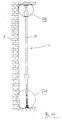
- FIG. 1 According to the embodiment in Figure 1 is provided in Area of an existing inner wall shell (1) for aligning an outer shell to be created (2) Use straightening elements (3).
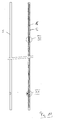
- Each of the straightening elements (3) consists of a frame (4), a layer rail (5) and cord fastening rods (6).
- Cord fastening rods (6) are provided to hold a vertical cord (7).
- cord fasteners (8) are used a horizontal cord between each of the two directional elements (3) (9) tension.
- the holding frame (4) is the one shown in FIG Installation situation with frame bases (10) in the area screwed to the inner wall shell (1).
- the frame base (10) carry cross struts (11) with a vertical rail (12) of the holding frame (4) are connected.
- the vertical cord (7) is aligned vertically in such a way that they are close to a side Limitation of the outer shell to be created (2) runs.
- the horizontal cord (9) is arranged in such a way that they are a respective layer of the to be created Masonry or the components to be used corresponds.
- Figure 3 shows an embodiment in which the holding frame (4) by means of a tensioning rail (15) in the area can be fixed by wall recesses.
- the bracing can, for example, by screw elements that can be removed respectively.
- a marking tape (16) is applied to facilitate vertical Position the cord attachment (8) at height a respective horizontal joint is on the layer rail (5) .
- the Marking tape (16) preferably has a line division at the distance of the respective joints. Is also thought of marking tape (16) to execute. There can be different ones as needed Marking tapes (16) each with the stone dimensions and line spacing adapted to the joint density be used.
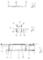
- a spacer element (17) is shown in FIG is used in the area of single stone elements, the corner areas of the outer shell to be created (5) be spaced.
- the spacer (17) consists essentially of a vertical element (18) and two supporting elements (19).
- Figure 5 shows a template (20) with markings (21).
- the template (20) is used to determine the attachment points for the holding frame (4).
- the markings (21) can, for example, as notches or Drilled holes.
- FIG. 6 shows the holding frame (4) in further views. with frame bases (10) and cross struts (11).
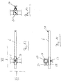
- FIG. 7 In the enlarged detail in FIG. 7 an embodiment is shown again in which in the area of the layer rails to be positioned (5) Longitudinal slots are provided around the layer rails (5) relative to a mounting bolt in to be able to move vertically.
- the fastening bolt engages in that shown in Figure 7 Bracket nut (22).
- Bracket nut (22) can instead of using longitudinal slots and bracket nuts (22) but also a sliding clamp fixation be used.
- Figure 8 shows again in an enlarged view the arrangement of cross struts (11) and Stiffening (13) of the holding frame (4).
- Figure 9 is to recognize that in the area of the frame base (10) slot-like recesses (23) are arranged to after a screw connection in the area of the inner shell (1) and before the screw connection is finally tightened to be able to carry out an adjustment.
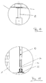
- Figure 10 shows an enlarged view of the Arrangement of the marking tape (16) in the area of Layer rail (5).
- Figure 11 shows an enlarged view of the training the layer rail (5) when using a Longitudinal slot as an alternative to the construction with movable clamping elements.
- FIG 12 is in various representations Cord attachment (8) for holding the vertical cord (7) shown.
- the cord attachment (8) essentially designed as a rider (24) can be fixed using a wing screw (25) is.
- the rider (24) indicates a displaceability a design according to a U-Profii. The Manageability can be achieved with a top view through a design supported according to an H profile.
- Figure 13 shows the arrangement of the cord fastening rod (6) in the area of the layer rail (5).
- the cord fastening rod (6) By a corresponding guide is the cord fastening rod (6) both in its longitudinal direction and transversely to its longitudinal direction relative to the layer rail (5) positionable.
- a Fixation in the intended position also via a wing screw (27) can be done. It is both a thumbscrew (27) for fixing in the longitudinal direction of the cord fastening rod (6) as well as another wing screw (27) for fixation transversely to the longitudinal direction the cord fastening rod (6) is provided.
- Figure 15 illustrates the fastening and Fixing principle of the cord fastening rod (6). It it can be seen in particular from this illustration that the cord fastening rod (6) within a sleeve (28), which in turn is associated with a Sleeve (29) is connected along the layer rail (5) is movable. The respective displacement movements can after loosening the wing screws (27) can be carried out. After reaching the intended Positioning is done by tightening the Wing screws (27) fix the location. On one The end of the cord fastening rod (6) is a cord holder (30) positioned.
- FIG. 1 The enlarged representation in FIG Mounting situation of a holding frame (4) shown, the using a vertical rail (12) for fixation is installed within a wall recess.
- Figure 19 shows an enlarged view once the template (20) with markings (21).
- Figure 20 illustrates the arrangement of the spacer elements (17) in the area of the outer shell (2). Through the Support elements (19) of the spacer elements (17) intended distance of the individual stone elements to each other guaranteed.
- FIG 21 there are different variants for the clamping Connection of the holding frame (4) to the layer rail (5).
- This embodiment can be used come when longitudinal slots are dispensed with should.
- the clamp bracket consists essentially of an outer sleeve (35) which has a wing screw (36) wearing. When the wing screw (36) is tightened the outer sleeve (35), the holding frame (4) and the Layer rail (5) braced against each other.
- the marking dimension results from the intended dimensioning the air layer between the inner wall shell (1) and the outer shell (2) and the dimensions the connecting stones.
- the holding frame (4) After drilling the holes using the template (20) is the holding frame (4) first with the help of Mounting screws mounted and then in two Directions aligned vertically. Then will by tightening the screws the fixation of the holding frame (4) performed. Then on the layer rail the necessary for the stones used Marking tape (16) has been applied, the Layer rail (5) mounted on the holding frame (4) and aligned.
- cord attachment rods (6) As an alternative to using cord attachment rods (6) is also possible, essentially to the cord attachment rods (6) to use identical holding rods, which can be positioned along the layer rail (5) and are definable. Hold the handrails however not a vertical line (7), but a contact rod. Such a system bar offers opposite the use of a vertical cord (7) advantages because even in the event of possible external influences the linear alignment is maintained.
- the mounting rods (6) Cords, stop bars or other components held that provide the chosen alignment escape As an alternative to a given vertical Alignment, in particular, is also possible through appropriate positioning of the components selected to define oblique arrangements.
Landscapes
- Engineering & Computer Science (AREA)
- Architecture (AREA)
- Mechanical Engineering (AREA)
- Civil Engineering (AREA)
- Structural Engineering (AREA)
- Conveying And Assembling Of Building Elements In Situ (AREA)
Applications Claiming Priority (2)
| Application Number | Priority Date | Filing Date | Title |
|---|---|---|---|
| DE1998122212 DE19822212A1 (de) | 1998-05-18 | 1998-05-18 | Vorrichtung zur Ausrichtung von Bauelementen |
| DE19822212 | 1998-05-18 |
Publications (1)
| Publication Number | Publication Date |
|---|---|
| EP0959200A1 true EP0959200A1 (fr) | 1999-11-24 |
Family
ID=7868133
Family Applications (1)
| Application Number | Title | Priority Date | Filing Date |
|---|---|---|---|
| EP99109596A Withdrawn EP0959200A1 (fr) | 1998-05-18 | 1999-05-14 | Dispositif pour l'alignement d'éléments de construction |
Country Status (2)
| Country | Link |
|---|---|
| EP (1) | EP0959200A1 (fr) |
| DE (1) | DE19822212A1 (fr) |
Cited By (1)
| Publication number | Priority date | Publication date | Assignee | Title |
|---|---|---|---|---|
| NL1017419C2 (nl) * | 2001-02-21 | 2002-08-22 | Adriaan Johan Van De Wal | Systeem voor het stellen van een richtelement en koppelmiddelen voor toepassing in een dergelijk systeem. |
Citations (12)
| Publication number | Priority date | Publication date | Assignee | Title |
|---|---|---|---|---|
| US1872860A (en) * | 1928-06-25 | 1932-08-23 | Winter Walter | Corner guide for bricklaying |
| US2788579A (en) * | 1956-02-24 | 1957-04-16 | John W Mills | Guide means for masons |
| GB776992A (en) * | 1954-11-26 | 1957-06-12 | Albert Benjamin David Boswell | Improvements in or relating to bricklayers guides |
| US2858613A (en) * | 1957-07-26 | 1958-11-04 | Harry W Best | Masonry wall and corner guide |
| US3063152A (en) * | 1959-06-10 | 1962-11-13 | William A Colbert | Guide for laying bricks |
| CH367617A (de) * | 1959-04-10 | 1963-02-28 | Blechwarenfabrik Muri Ag | Richtlineal |
| US3127683A (en) * | 1961-10-23 | 1964-04-07 | Structural Clay Products Res F | Universal mason's corner pole |
| US4144649A (en) * | 1977-08-11 | 1979-03-20 | Huston Charles W | Brick alignment pole |
| DE3212090A1 (de) * | 1981-08-13 | 1983-03-03 | Heinz 4518 Bad Laer Hummel | Richtscheitklammer zum festlegen eines richtscheites |
| US4995167A (en) * | 1989-03-24 | 1991-02-26 | William Sanchez | Masonry guide |
| WO1991003613A1 (fr) * | 1989-08-31 | 1991-03-21 | Roy Elmer Sarasin | Echelle de maçon graduee et guide pour maçonnerie utilisant une telle echelle |
| US5136785A (en) * | 1991-12-12 | 1992-08-11 | Shirley Coyt C | Apparatus for constructing masonry corners |
-
1998
- 1998-05-18 DE DE1998122212 patent/DE19822212A1/de not_active Withdrawn
-
1999
- 1999-05-14 EP EP99109596A patent/EP0959200A1/fr not_active Withdrawn
Patent Citations (12)
| Publication number | Priority date | Publication date | Assignee | Title |
|---|---|---|---|---|
| US1872860A (en) * | 1928-06-25 | 1932-08-23 | Winter Walter | Corner guide for bricklaying |
| GB776992A (en) * | 1954-11-26 | 1957-06-12 | Albert Benjamin David Boswell | Improvements in or relating to bricklayers guides |
| US2788579A (en) * | 1956-02-24 | 1957-04-16 | John W Mills | Guide means for masons |
| US2858613A (en) * | 1957-07-26 | 1958-11-04 | Harry W Best | Masonry wall and corner guide |
| CH367617A (de) * | 1959-04-10 | 1963-02-28 | Blechwarenfabrik Muri Ag | Richtlineal |
| US3063152A (en) * | 1959-06-10 | 1962-11-13 | William A Colbert | Guide for laying bricks |
| US3127683A (en) * | 1961-10-23 | 1964-04-07 | Structural Clay Products Res F | Universal mason's corner pole |
| US4144649A (en) * | 1977-08-11 | 1979-03-20 | Huston Charles W | Brick alignment pole |
| DE3212090A1 (de) * | 1981-08-13 | 1983-03-03 | Heinz 4518 Bad Laer Hummel | Richtscheitklammer zum festlegen eines richtscheites |
| US4995167A (en) * | 1989-03-24 | 1991-02-26 | William Sanchez | Masonry guide |
| WO1991003613A1 (fr) * | 1989-08-31 | 1991-03-21 | Roy Elmer Sarasin | Echelle de maçon graduee et guide pour maçonnerie utilisant une telle echelle |
| US5136785A (en) * | 1991-12-12 | 1992-08-11 | Shirley Coyt C | Apparatus for constructing masonry corners |
Cited By (1)
| Publication number | Priority date | Publication date | Assignee | Title |
|---|---|---|---|---|
| NL1017419C2 (nl) * | 2001-02-21 | 2002-08-22 | Adriaan Johan Van De Wal | Systeem voor het stellen van een richtelement en koppelmiddelen voor toepassing in een dergelijk systeem. |
Also Published As
| Publication number | Publication date |
|---|---|
| DE19822212A1 (de) | 1999-11-25 |
Similar Documents
| Publication | Publication Date | Title |
|---|---|---|
| DE69803731T2 (de) | Verfahren und vorrichtung zum einbau eines aufzugs | |
| EP0801188B1 (fr) | Coffrage d'encorbellement pour constructions | |
| DE29517360U1 (de) | Ausrichtbare Pfostenhalterung | |
| DE4438690C2 (de) | Putzabziehhilfe und Putzabziehverfahren | |
| EP0799935B1 (fr) | Coffrage de bord | |
| DE3700904C2 (fr) | ||
| DE4436260A1 (de) | Verfahren zur Herstellung eines Gleiskörpers im schotterlosen Oberbau und Vorrichtung zur Durchführung des Verfahrens | |
| EP0959200A1 (fr) | Dispositif pour l'alignement d'éléments de construction | |
| EP4012131B1 (fr) | Dispositif de fixation et procédé d'alignement et de fixation d'un profilé de poteau d'une construction à poteaux et à traverses | |
| DE19923814C1 (de) | Montagezwinge für den Einbau von Fenstern und Türen | |
| EP3922784A1 (fr) | Dispositif de nivellement et de retrait | |
| DE102011102486B4 (de) | Halterung für ein Gerüstbauteil oder eine Abstürzsicherung | |
| DE4438454C2 (de) | Montagevorrichtung | |
| EP4729715A1 (fr) | Aide au montage et procédé de montage | |
| DE19509402C1 (de) | Stützeinrichtung | |
| DE29922481U1 (de) | Vorrichtung zur verfahrbaren Anordnung einer Schiebetür an einer Türöffnung | |
| DE10017564A1 (de) | Vorrichtung zur Positionierung von Stützen zur Aufnahme von Bodenplatten für einen doppelten Boden | |
| WO2001055532A1 (fr) | Dispositif permettant de faciliter les ouvrages de maconnerie et procede permettant d'eriger des murs | |
| DE19507356C2 (de) | Vorrichtung und Verfahren zur Vorgabe aufeinanderfolgender Bearbeitungspunkte oder -bereiche an einem Bauteil sowie Verwendung | |
| AT519309B1 (de) | Befestigungswinkel für deckenrandabschalungen | |
| DE2247555A1 (de) | Montagegeruest fuer aufzustellende wandelemente mit und ohne wandoeffnungsauskleidungen | |
| DE9409792U1 (de) | Halterungsanordnung für das Leitseil von leitseilgesteuerten Gleisbaumaschinen, für Flatterleinen, starre Gleisabsperrungen o.dgl. | |
| DE2127738A1 (de) | Vorrichtung zum Positionieren von Bohrlöchern | |
| DE20000552U1 (de) | Profilschienensystem | |
| DE6606063U (de) | Vorrichtung zum befestigen von vorgehaengten fassadenplatten an bauwerken |
Legal Events
| Date | Code | Title | Description |
|---|---|---|---|
| PUAI | Public reference made under article 153(3) epc to a published international application that has entered the european phase |
Free format text: ORIGINAL CODE: 0009012 |
|
| AK | Designated contracting states |
Kind code of ref document: A1 Designated state(s): DK NL |
|
| AX | Request for extension of the european patent |
Free format text: AL;LT;LV;MK;RO;SI |
|
| 17P | Request for examination filed |
Effective date: 20000304 |
|
| AKX | Designation fees paid |
Free format text: DK NL |
|
| REG | Reference to a national code |
Ref country code: DE Ref legal event code: 8566 |
|
| STAA | Information on the status of an ep patent application or granted ep patent |
Free format text: STATUS: THE APPLICATION IS DEEMED TO BE WITHDRAWN |
|
| 18D | Application deemed to be withdrawn |
Effective date: 20011201 |