EP0959273A2 - Joint d'étanchéité, en particulier pour véhicule automobile - Google Patents
Joint d'étanchéité, en particulier pour véhicule automobile Download PDFInfo
- Publication number
- EP0959273A2 EP0959273A2 EP99106295A EP99106295A EP0959273A2 EP 0959273 A2 EP0959273 A2 EP 0959273A2 EP 99106295 A EP99106295 A EP 99106295A EP 99106295 A EP99106295 A EP 99106295A EP 0959273 A2 EP0959273 A2 EP 0959273A2
- Authority
- EP
- European Patent Office
- Prior art keywords
- iii
- screw
- metal layer
- sheet metal
- hole
- Prior art date
- Legal status (The legal status is an assumption and is not a legal conclusion. Google has not performed a legal analysis and makes no representation as to the accuracy of the status listed.)
- Granted
Links
- 210000002105 tongue Anatomy 0.000 claims description 53
- 239000002184 metal Substances 0.000 claims description 27
- 238000007789 sealing Methods 0.000 description 13
- 238000005452 bending Methods 0.000 description 3
- 238000004519 manufacturing process Methods 0.000 description 3
- 230000002265 prevention Effects 0.000 description 3
- 238000004080 punching Methods 0.000 description 3
- 239000011248 coating agent Substances 0.000 description 1
- 238000000576 coating method Methods 0.000 description 1
- 150000001875 compounds Chemical class 0.000 description 1
- 238000004049 embossing Methods 0.000 description 1
- 239000000463 material Substances 0.000 description 1
- 238000000034 method Methods 0.000 description 1
- 238000012986 modification Methods 0.000 description 1
- 230000004048 modification Effects 0.000 description 1
Images

Classifications
-
- F—MECHANICAL ENGINEERING; LIGHTING; HEATING; WEAPONS; BLASTING
- F16—ENGINEERING ELEMENTS AND UNITS; GENERAL MEASURES FOR PRODUCING AND MAINTAINING EFFECTIVE FUNCTIONING OF MACHINES OR INSTALLATIONS; THERMAL INSULATION IN GENERAL
- F16J—PISTONS; CYLINDERS; SEALINGS
- F16J15/00—Sealings
- F16J15/02—Sealings between relatively-stationary surfaces
- F16J15/06—Sealings between relatively-stationary surfaces with solid packing compressed between sealing surfaces
- F16J15/064—Sealings between relatively-stationary surfaces with solid packing compressed between sealing surfaces the packing combining the sealing function with other functions
Definitions
- the invention relates to a seal, in particular a seal for a motor vehicle component which has at least one Has sheet metal layer, the at least one screw hole for the Passage of the threaded shaft of a screw.
- Loss protection devices for screws are in various forms known; so shows z.
- B. DE-U-87 08 965 a head screw with one made from an elastic plastic Pad which has a screw hole for the passage of the threaded shaft of the cap screw and a captive lock for the cap screw to the latter on the Hold document.
- Plastic support is four integral tongues formed, which before inserting the cap screw into the Screw hole of the pad all in a common to the retaining tongues Level, and the cap screw has between an annular groove in its head and its threaded shaft, into which the Retain tabs engage after the threaded shaft is under elastic deflection of the retaining tongues through the screw hole the pad was pushed through.
- this task can be done solve according to the invention that from the edge of the screw hole several holding tongues in one piece with the sheet metal layer protrude, which is distributed over the circumference of the hole and at a distance are arranged from each other that the hole center facing Edge areas of the holding tongues - in the axial direction of the Seen screw hole - define a circular core hole, the diameter of which corresponds to the core diameter of the screw thread corresponds to the width of the retaining tongues as well as the Thickness of the sheet metal layer at least in the hole center Edge areas of the retaining tongues their engagement in the Allows screw threads, and that at least part of the Retaining tongues bent out of the plane of the sheet metal layer in this way is that the edge areas facing the hole center of the Retaining tongues corresponding to the pitch of the screw thread offset from each other in the axial direction of the screw hole are arranged.
- Such holding tongues can be designed with a punching and bending tool in the manufacture of the screw hole, if necessary even in the course of punching out the sheet metal layer simultaneous production of the screw hole, both punch out bend as well, the tool being so can be designed that the sheet metal layer after the implementation the punching and bending process itself from the tool falls out.
- the sheet metal layer has one by default Sheet thickness, which would not allow the retaining tongues can engage in the screw thread with the tool the sheet thickness of the edge areas facing the hole center the retaining tongues easily by embossing like this be reduced that these edge areas then in the screw thread can intervene.
- the invention Loss prevention against the following further advantages: If the screw is inserted into the Twisted seal, no effort is required; the elastically deflectable holding tongues also leave it there to the screw without turning it into the Screw hole is inserted while pushing back the screw or only with a relatively high effort is possible.
- each from the plane of the sheet metal layer bent out tongue both in the area of its root and also near their edge area facing the hole center is angled that the latter is at least approximately runs parallel to the level of the sheet metal layer, because then stand the edge areas of all holding tongues near the center perpendicular in Screw thread.
- the inventive design is particularly simple Loss prevention when one of the retaining tongues is level and lies in the plane of the sheet metal layer, since then only the second or all other retaining tabs are bent out of the sheet metal layer must or must.
- the screw is well centered when the Edge areas of the retaining tongues facing the center of the hole Have a corresponding circular arc-shaped contour, although of course embodiments are also conceivable for which the edge areas of the holding tongues facing the hole center e.g. B. a triangular or convex semicircular Have a contour.
- the hole center facing edge areas of the retaining tongues proportionately be narrow, which is why in terms of the desired Centering the screw in the screw hole embodiments with more than two retaining tongues are preferred, in particular Embodiments with three at equal angular distances from each other arranged holding tongues.
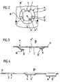
- Fig. 1 shows part of a seal 10
- the sealing plate 12 is formed by a single sheet layer, which on one or both sides with the entire surface or partially coated with a particularly elastomeric sealing compound can be.
- the sealing plate 12 three with captive locks according to the invention provided screw holes 14, 16, 18 for the Passage of the threaded shafts of cap screws, not shown.
- the screw holes can all be identical, and based on Figures 2 to 4, the design of the am Screw hole 14 provided captive described in more detail become.
- the screw hole 14 has one of several circular arc segments formed edge 14 ', which is a circle with a diameter defined, which is equal to the diameter of conventionally designed
- edge 14 ' is a circle with a diameter defined, which is equal to the diameter of conventionally designed
- screw holes in the sealing plates From Screw hole edge 14 'are facing inwards, i. H. in the direction on a hole center 14 '', three holding tongues I, II and III, which are arranged at equal angular distances from each other are and are formed from the sheet of the sealing plate 12.
- Inner edge regions of the holding tongues facing the hole center 14 ′′ I to III were designated I ', II' and III '; the Edges of these inner edge regions facing the hole center 14 ′′ are also circular arcs and define a circular core hole concentric to the hole center 14 '' 14 '' ', the diameter of which is only slightly larger than the core diameter of the thread of the cap screw to be held.
- Each of the tabs II and III is both in the area of their Root as well as at the radially outer end of its inner edge area II 'and III' each bent at an obtuse angle so that a cross-section in the form of a somewhat flat Z results.
- the inner edge regions II 'and III' run parallel to the plane of the sealing plate 12, but in such a way different distances from the actual sealing plate (measured in the direction of arrow S) that the inner Edge areas I ', II' and III '(taking into account their angular distances from each other) corresponding to the pitch of the screw thread in the direction of arrow S offset from each other are.
- the width measured in the circumferential direction of the screw hole 14 the retaining tongues I to III was taking into account the Sheet thickness of the sealing plate 12 chosen so that the inner Edge areas I ', II' and III 'so in the thread or the threads of the screw to be held can intervene, that at least no significant deformation of the retaining tongues I to III occurs.
Landscapes
- Engineering & Computer Science (AREA)
- General Engineering & Computer Science (AREA)
- Mechanical Engineering (AREA)
- Gasket Seals (AREA)
- Connection Of Plates (AREA)
- Motor Or Generator Frames (AREA)
- Sealing Using Fluids, Sealing Without Contact, And Removal Of Oil (AREA)
Applications Claiming Priority (2)
| Application Number | Priority Date | Filing Date | Title |
|---|---|---|---|
| DE29809130U DE29809130U1 (de) | 1998-05-20 | 1998-05-20 | Dichtung, insbesondere für Kraftfahrzeuge |
| DE29809130U | 1998-05-20 |
Publications (3)
| Publication Number | Publication Date |
|---|---|
| EP0959273A2 true EP0959273A2 (fr) | 1999-11-24 |
| EP0959273A3 EP0959273A3 (fr) | 1999-12-01 |
| EP0959273B1 EP0959273B1 (fr) | 2003-09-03 |
Family
ID=8057461
Family Applications (1)
| Application Number | Title | Priority Date | Filing Date |
|---|---|---|---|
| EP99106295A Expired - Lifetime EP0959273B1 (fr) | 1998-05-20 | 1999-04-16 | Joint d'étanchéité, en particulier pour véhicule automobile |
Country Status (6)
| Country | Link |
|---|---|
| US (1) | US6371492B1 (fr) |
| EP (1) | EP0959273B1 (fr) |
| JP (1) | JP3188881B2 (fr) |
| BR (1) | BR9902092A (fr) |
| DE (2) | DE29809130U1 (fr) |
| ES (1) | ES2202949T3 (fr) |
Cited By (1)
| Publication number | Priority date | Publication date | Assignee | Title |
|---|---|---|---|---|
| WO2004085891A1 (fr) * | 2003-03-27 | 2004-10-07 | Federal-Mogul Sealing Systems Bretten Gmbh | Garniture d'etancheite elastomere indeformable |
Families Citing this family (9)
| Publication number | Priority date | Publication date | Assignee | Title |
|---|---|---|---|---|
| DE19932727C1 (de) * | 1999-07-14 | 2000-11-30 | Elringklinger Gmbh | Dichtung, insbesondere für Kraftfahrzeuge |
| DE10107939B4 (de) * | 2001-02-20 | 2012-06-14 | Pierburg Gmbh | Flachdichtung |
| JP3762250B2 (ja) * | 2001-05-15 | 2006-04-05 | トヨタ自動車株式会社 | 金属ガスケット |
| US6533287B1 (en) * | 2001-11-21 | 2003-03-18 | Dana Corporation | Bolt retention mechanism for MLS gasket |
| US6926286B2 (en) | 2002-03-28 | 2005-08-09 | Nichias Corporation | Gasket holding device |
| US20070216109A1 (en) * | 2006-03-16 | 2007-09-20 | Elringklinger Ag | Turbocharger gasket |
| DE102012215872A1 (de) * | 2012-09-07 | 2014-03-13 | Rohde & Schwarz Gmbh & Co. Kg | Ausfallsicherungselement sowie Anordnung und Verfahren zur unverlierbaren Montage einer Schraube an einem Kabelschuh |
| DE112014000377T5 (de) * | 2013-02-25 | 2015-09-24 | Shiloh Industries, Inc. | Modulare Baugruppe mit Presssitzbefestigungselementaussparungen |
| US9055983B1 (en) * | 2014-04-24 | 2015-06-16 | Amendia, Inc. | Self-locking bone screw receiver |
Citations (1)
| Publication number | Priority date | Publication date | Assignee | Title |
|---|---|---|---|---|
| DE8708965U1 (de) | 1987-06-29 | 1988-10-27 | Robert Bosch Gmbh, 7000 Stuttgart | Verliersicherung für Schrauben, insbesondere für Kopfschrauben, an elastischen Unterlagen |
Family Cites Families (7)
| Publication number | Priority date | Publication date | Assignee | Title |
|---|---|---|---|---|
| US2117775A (en) * | 1936-12-03 | 1938-05-17 | Albert H Tinnerman | Fastening device |
| US2221498A (en) * | 1937-10-04 | 1940-11-12 | Tinnerman Products Inc | Sheet metal fastening means |
| US4784396A (en) * | 1987-06-01 | 1988-11-15 | Ford Motor Company | Retaining clip and gasket for engine subassembly |
| US5544902A (en) * | 1994-06-30 | 1996-08-13 | Dana Corporation | Metal gasket with bolt retention freature |
| US5513855A (en) * | 1994-07-05 | 1996-05-07 | Ishikawa Gasket Co., Ltd. | Metal laminate gasket with engaging device having curved edges |
| JP3666827B2 (ja) * | 1995-10-27 | 2005-06-29 | 株式会社青山製作所 | ねじ締付用クリップ |
| US5673920A (en) * | 1996-09-16 | 1997-10-07 | Fel-Pro Incorporated | Gasket bolt hole with retaining beam and slot |
-
1998
- 1998-05-20 DE DE29809130U patent/DE29809130U1/de not_active Expired - Lifetime
-
1999
- 1999-04-16 EP EP99106295A patent/EP0959273B1/fr not_active Expired - Lifetime
- 1999-04-16 DE DE59906824T patent/DE59906824D1/de not_active Expired - Fee Related
- 1999-04-16 ES ES99106295T patent/ES2202949T3/es not_active Expired - Lifetime
- 1999-05-18 US US09/313,887 patent/US6371492B1/en not_active Expired - Fee Related
- 1999-05-19 BR BR9902092-0A patent/BR9902092A/pt not_active IP Right Cessation
- 1999-05-20 JP JP14014699A patent/JP3188881B2/ja not_active Expired - Fee Related
Patent Citations (1)
| Publication number | Priority date | Publication date | Assignee | Title |
|---|---|---|---|---|
| DE8708965U1 (de) | 1987-06-29 | 1988-10-27 | Robert Bosch Gmbh, 7000 Stuttgart | Verliersicherung für Schrauben, insbesondere für Kopfschrauben, an elastischen Unterlagen |
Cited By (1)
| Publication number | Priority date | Publication date | Assignee | Title |
|---|---|---|---|---|
| WO2004085891A1 (fr) * | 2003-03-27 | 2004-10-07 | Federal-Mogul Sealing Systems Bretten Gmbh | Garniture d'etancheite elastomere indeformable |
Also Published As
| Publication number | Publication date |
|---|---|
| EP0959273B1 (fr) | 2003-09-03 |
| EP0959273A3 (fr) | 1999-12-01 |
| DE29809130U1 (de) | 1998-09-03 |
| US6371492B1 (en) | 2002-04-16 |
| DE59906824D1 (de) | 2003-10-09 |
| JP3188881B2 (ja) | 2001-07-16 |
| ES2202949T3 (es) | 2004-04-01 |
| BR9902092A (pt) | 2000-01-11 |
| JP2000027996A (ja) | 2000-01-25 |
Similar Documents
| Publication | Publication Date | Title |
|---|---|---|
| EP2594813B1 (fr) | Elément de rivet aveugle | |
| EP0959273B1 (fr) | Joint d'étanchéité, en particulier pour véhicule automobile | |
| EP3433515B1 (fr) | Dispositif d'étanchéité et procédé de fabrication d'un dispositif d'étanchéité | |
| EP1181460B1 (fr) | Dispositif d'assemblage | |
| EP3707396A1 (fr) | Dispositif anti-détachement pour vis et unité de montage | |
| DE102013110429A1 (de) | Kunststoff-Befestigungselement sowie Befestigungsanordnung hiermit | |
| DE10220233A1 (de) | Mutter und Verfahren zu ihrer Herstellung | |
| DE102014009410B4 (de) | Verfahren zum Verbinden eines Einpressbolzens mit einem ein Vorloch aufweisenden Blechteil und Abdeckelement zur Durchführung des Verfahrens | |
| EP1503096B1 (fr) | Organe de retenue pour la fixation d'au moins un palier | |
| DE20120029U1 (de) | Stutzen für eine Behälterwand | |
| DE2220657A1 (de) | Anordnung zum befestigen zweier bauteile | |
| EP3974680A1 (fr) | Roue à composants multiples, pignon et train épicycloïdal | |
| DE3329967A1 (de) | Schraub- oder nietverbindung | |
| DE102011106989A1 (de) | Befestigungselement sowie Verfahren zum Herstellen einer Befestigungsanordnung | |
| DE4313845C1 (de) | Sicherungsmutter | |
| DE102021213541B3 (de) | Zahnrad | |
| EP3956572B1 (fr) | Unité de raccordement et procédé de fabrication d'une unité de raccordement | |
| DE10117851C2 (de) | Verbindungsvorrichtung | |
| DE102016012978A1 (de) | Planetengetriebe mit einem Planetenträger und einer Planetenradachse | |
| DE19932727C1 (de) | Dichtung, insbesondere für Kraftfahrzeuge | |
| DE102020109386A1 (de) | Verdrehsicherung für eine Schraube oder eine Schraubenmutter | |
| EP0930439A1 (fr) | Fixation d'au moins deux tÔles l'une sur l'autre au moyen d'une vis auto-foreuse | |
| EP1380761B1 (fr) | Elément de fixation pour une ouverture dans une paroi, en particulier d'une carrosserie de véhicule | |
| DE20201112U1 (de) | Stutzen für ein Wandteil, insbesondere für ein Wandteil eines Deckels oder Behälters | |
| DE19624141C2 (de) | Gummiformdichtung |
Legal Events
| Date | Code | Title | Description |
|---|---|---|---|
| PUAI | Public reference made under article 153(3) epc to a published international application that has entered the european phase |
Free format text: ORIGINAL CODE: 0009012 |
|
| PUAL | Search report despatched |
Free format text: ORIGINAL CODE: 0009013 |
|
| AK | Designated contracting states |
Kind code of ref document: A2 Designated state(s): DE ES FR GB IT |
|
| AX | Request for extension of the european patent |
Free format text: AL;LT;LV;MK;RO;SI |
|
| AK | Designated contracting states |
Kind code of ref document: A3 Designated state(s): AT BE CH CY DE DK ES FI FR GB GR IE IT LI LU MC NL PT SE |
|
| AX | Request for extension of the european patent |
Free format text: AL;LT;LV;MK;RO;SI |
|
| RIC1 | Information provided on ipc code assigned before grant |
Free format text: 6F 16J 15/08 A |
|
| 17P | Request for examination filed |
Effective date: 19991106 |
|
| AKX | Designation fees paid |
Free format text: DE ES FR GB IT |
|
| RAP1 | Party data changed (applicant data changed or rights of an application transferred) |
Owner name: ELRINGKLINGER AG |
|
| RAP1 | Party data changed (applicant data changed or rights of an application transferred) |
Owner name: ELRINGKLINGER AG |
|
| GRAH | Despatch of communication of intention to grant a patent |
Free format text: ORIGINAL CODE: EPIDOS IGRA |
|
| GRAS | Grant fee paid |
Free format text: ORIGINAL CODE: EPIDOSNIGR3 |
|
| GRAA | (expected) grant |
Free format text: ORIGINAL CODE: 0009210 |
|
| AK | Designated contracting states |
Kind code of ref document: B1 Designated state(s): DE ES FR GB IT |
|
| REG | Reference to a national code |
Ref country code: GB Ref legal event code: FG4D Free format text: NOT ENGLISH |
|
| REF | Corresponds to: |
Ref document number: 59906824 Country of ref document: DE Date of ref document: 20031009 Kind code of ref document: P |
|
| GBT | Gb: translation of ep patent filed (gb section 77(6)(a)/1977) |
Effective date: 20031119 |
|
| REG | Reference to a national code |
Ref country code: ES Ref legal event code: FG2A Ref document number: 2202949 Country of ref document: ES Kind code of ref document: T3 |
|
| ET | Fr: translation filed | ||
| PLBE | No opposition filed within time limit |
Free format text: ORIGINAL CODE: 0009261 |
|
| STAA | Information on the status of an ep patent application or granted ep patent |
Free format text: STATUS: NO OPPOSITION FILED WITHIN TIME LIMIT |
|
| 26N | No opposition filed |
Effective date: 20040604 |
|
| PGFP | Annual fee paid to national office [announced via postgrant information from national office to epo] |
Ref country code: ES Payment date: 20090318 Year of fee payment: 11 |
|
| PGFP | Annual fee paid to national office [announced via postgrant information from national office to epo] |
Ref country code: GB Payment date: 20090303 Year of fee payment: 11 |
|
| PGFP | Annual fee paid to national office [announced via postgrant information from national office to epo] |
Ref country code: IT Payment date: 20090324 Year of fee payment: 11 Ref country code: FR Payment date: 20090416 Year of fee payment: 11 Ref country code: DE Payment date: 20090529 Year of fee payment: 11 |
|
| GBPC | Gb: european patent ceased through non-payment of renewal fee |
Effective date: 20100416 |
|
| REG | Reference to a national code |
Ref country code: FR Ref legal event code: ST Effective date: 20101230 |
|
| PG25 | Lapsed in a contracting state [announced via postgrant information from national office to epo] |
Ref country code: DE Free format text: LAPSE BECAUSE OF NON-PAYMENT OF DUE FEES Effective date: 20101103 |
|
| PG25 | Lapsed in a contracting state [announced via postgrant information from national office to epo] |
Ref country code: IT Free format text: LAPSE BECAUSE OF NON-PAYMENT OF DUE FEES Effective date: 20100416 Ref country code: GB Free format text: LAPSE BECAUSE OF NON-PAYMENT OF DUE FEES Effective date: 20100416 |
|
| REG | Reference to a national code |
Ref country code: ES Ref legal event code: FD2A Effective date: 20110715 |
|
| PG25 | Lapsed in a contracting state [announced via postgrant information from national office to epo] |
Ref country code: ES Free format text: LAPSE BECAUSE OF NON-PAYMENT OF DUE FEES Effective date: 20110705 |
|
| PG25 | Lapsed in a contracting state [announced via postgrant information from national office to epo] |
Ref country code: ES Free format text: LAPSE BECAUSE OF NON-PAYMENT OF DUE FEES Effective date: 20100417 |
|
| PG25 | Lapsed in a contracting state [announced via postgrant information from national office to epo] |
Ref country code: FR Free format text: LAPSE BECAUSE OF NON-PAYMENT OF DUE FEES Effective date: 20100430 |