EP0959302A2 - Silencieux pour gaine de fumées d'échappement - Google Patents
Silencieux pour gaine de fumées d'échappement Download PDFInfo
- Publication number
- EP0959302A2 EP0959302A2 EP99109672A EP99109672A EP0959302A2 EP 0959302 A2 EP0959302 A2 EP 0959302A2 EP 99109672 A EP99109672 A EP 99109672A EP 99109672 A EP99109672 A EP 99109672A EP 0959302 A2 EP0959302 A2 EP 0959302A2
- Authority
- EP
- European Patent Office
- Prior art keywords
- tube
- flue gas
- gas exhaust
- exhaust silencer
- silencer according
- Prior art date
- Legal status (The legal status is an assumption and is not a legal conclusion. Google has not performed a legal analysis and makes no representation as to the accuracy of the status listed.)
- Withdrawn
Links
Images

Classifications
-
- F—MECHANICAL ENGINEERING; LIGHTING; HEATING; WEAPONS; BLASTING
- F01—MACHINES OR ENGINES IN GENERAL; ENGINE PLANTS IN GENERAL; STEAM ENGINES
- F01N—GAS-FLOW SILENCERS OR EXHAUST APPARATUS FOR MACHINES OR ENGINES IN GENERAL; GAS-FLOW SILENCERS OR EXHAUST APPARATUS FOR INTERNAL-COMBUSTION ENGINES
- F01N13/00—Exhaust or silencing apparatus characterised by constructional features
- F01N13/18—Construction facilitating manufacture, assembly, or disassembly
- F01N13/1838—Construction facilitating manufacture, assembly, or disassembly characterised by the type of connection between parts of exhaust or silencing apparatus, e.g. between housing and tubes, between tubes and baffles
-
- F—MECHANICAL ENGINEERING; LIGHTING; HEATING; WEAPONS; BLASTING
- F01—MACHINES OR ENGINES IN GENERAL; ENGINE PLANTS IN GENERAL; STEAM ENGINES
- F01N—GAS-FLOW SILENCERS OR EXHAUST APPARATUS FOR MACHINES OR ENGINES IN GENERAL; GAS-FLOW SILENCERS OR EXHAUST APPARATUS FOR INTERNAL-COMBUSTION ENGINES
- F01N1/00—Silencing apparatus characterised by method of silencing
- F01N1/08—Silencing apparatus characterised by method of silencing by reducing exhaust energy by throttling or whirling
- F01N1/10—Silencing apparatus characterised by method of silencing by reducing exhaust energy by throttling or whirling in combination with sound-absorbing materials
-
- F—MECHANICAL ENGINEERING; LIGHTING; HEATING; WEAPONS; BLASTING
- F16—ENGINEERING ELEMENTS AND UNITS; GENERAL MEASURES FOR PRODUCING AND MAINTAINING EFFECTIVE FUNCTIONING OF MACHINES OR INSTALLATIONS; THERMAL INSULATION IN GENERAL
- F16L—PIPES; JOINTS OR FITTINGS FOR PIPES; SUPPORTS FOR PIPES, CABLES OR PROTECTIVE TUBING; MEANS FOR THERMAL INSULATION IN GENERAL
- F16L55/00—Devices or appurtenances for use in, or in connection with, pipes or pipe systems
- F16L55/02—Energy absorbers; Noise absorbers
- F16L55/033—Noise absorbers
-
- F—MECHANICAL ENGINEERING; LIGHTING; HEATING; WEAPONS; BLASTING
- F23—COMBUSTION APPARATUS; COMBUSTION PROCESSES
- F23J—REMOVAL OR TREATMENT OF COMBUSTION PRODUCTS OR COMBUSTION RESIDUES; FLUES
- F23J13/00—Fittings for chimneys or flues
-
- F—MECHANICAL ENGINEERING; LIGHTING; HEATING; WEAPONS; BLASTING
- F23—COMBUSTION APPARATUS; COMBUSTION PROCESSES
- F23J—REMOVAL OR TREATMENT OF COMBUSTION PRODUCTS OR COMBUSTION RESIDUES; FLUES
- F23J2900/00—Special arrangements for conducting or purifying combustion fumes; Treatment of fumes or ashes
- F23J2900/13003—Means for reducing the noise in smoke conducing ducts or systems
Definitions
- the invention relates in particular to a smoke exhaust muffler for boilers according to the preamble of the independent claim 1.
- Such smoke exhaust mufflers are known and in use, so that in this regard, no special printed evidence is required per se.
- Such exhaust mufflers are used to reduce the sound radiation from a boiler.
- Such flue gas exhaust mufflers have proven to be capable of improvement, and the invention is based on the object of improving a muffler of the type mentioned at the outset with a simple measure with regard to its sound insulation effect, and ultimately with the objective of optimizing the length of such mufflers due to optimized sound insulation so that the material and reduce manufacturing costs and thus also to be able to reduce the distance between the boiler and chimney.
- downstream end area of the inner tube to punch because of the inner tube extension there more or less transversely oriented flow components in the flow arise, which are then provided for there Openings or holes and the insulation pack behind them bump.
- the perforated transitions can be formed as integral, expanded parts of the inner tube.
- the perforated transitions can be formed as integral parts of the connecting piece.
- the connecting pieces are formed as integral parts of the end walls shaped in the manner of a clapper base and that the transitions are to be applied in the connection area of the connecting pieces.
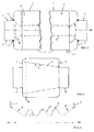
- the smoke exhaust muffler still consists of one Outer tube 1 with inner sound insulation pack 2, which between the Outer tube 1 and a flow channel 3 delimiting, with perforated wall 4 provided inner tube 5 is arranged, wherein the flow channel 3 in the interior of the outer tube 1 behind End walls 7 of the outer tube 1 with transitions 8 in one with respect to the outer diameter D of connecting piece 6 smaller Diameter D 'is reduced.
- FIGS. 2, 3 Regarding the embodiment in which the perforated transitions 8 formed as integral, expanded parts of the inner tube 5 are referred to FIGS. 2, 3 and with respect to Provided that the perforated transitions 8 as integral parts of the Connection piece 6 can be formed, on Fig. 4, right Side of the sectional view there.
- a condensate drain port 11 is arranged (see also Fig. 4, right side).
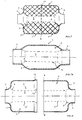
- FIG. 5 A special embodiment which has the same effect is shown in Fig. 5, according to which the connector 6 to 6 connecting piece, perforated inner tube 5 from the inflow side ZS to the outflow side AS, that is along its entire length, conical in the shape of a truncated cone is.
- the silencer is related shown comparatively shorter on the other representations, what with a correspondingly large cone angle and accordingly large outer diameter D '' also put into practice can become and in extreme a more disc-shaped Muffler leads the very close approach of a boiler to the chimney.
- the upstream end wall 7 as a separate "floor", such as indicated at B, appropriately scheduled or what is explained in more detail, the outer tube 1 is made of two halves or pipe parts 1 'in the sense of FIG. 7.
- the outer tube 1 from two tube parts 1 ' is formed with substantially the same shape and size that formed in one piece with the end walls 7 and at their abutting edges 1 '' are connected to each other in a gas-tight manner.
- the connecting piece 6 can also easily welded on as separate pipe sections be.
- the perforated inner tube 5 also from two to the division plane E of the outer tube 1 reaching parts 5 'formed with the end walls 7 are firmly connected. As you can imagine, can thereby the two pot-like open halves all around the inner tube parts 5 'comfortably filled with soundproofing halves become.
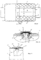
- each outer tube half receives a parabolic contour, what also a favorable shaping process every half in one Piece comes towards.
- such a shape has the Advantage that condensate occurring in the silencer is targeted runs to the center and there through a condensate drain 11, as shown in Fig. 9 can be derived.
- the inner tube 5 has a smaller diameter D than the connecting piece 6 and to this or the end walls 7 with frustoconical transitions 8 are also connected in this case the walls 8 'of the frusto-conical transitions 8 also formed perforated, namely from the introduction reasons mentioned.
- the halves forming the muffler in the area of their parting or connecting plane E are preferably mechanical M connected to each other in a gastight manner, as this is greatly enlarged in Fig.10 is shown.
- the plug-in extensions 12 of one half and the bumper edge 1 '' of the other half perforated flush with each other and by so-called pop rivets 13 firmly bonded together using heat resistant sealant 14 can be inserted.
- the whole thing can still, then with the insertion of sealant 14 with a suitable one Way covered hollow bandage 15 may be covered.
- the insulation pack 2 can namely easily as either loose Material or in the form of insulation mat cuts from one and / or other side inserted through the connector 6 or are plugged in, after which, if necessary, with an inner tube 5 superior, conical auxiliary tool this one or is pushed through, after which, positioned, the two Ends of the inner tube 5 on the inside of the recessed connecting piece 6 can be easily pinned.
Landscapes
- Engineering & Computer Science (AREA)
- General Engineering & Computer Science (AREA)
- Mechanical Engineering (AREA)
- Chemical & Material Sciences (AREA)
- Combustion & Propulsion (AREA)
- Exhaust Silencers (AREA)
Applications Claiming Priority (4)
| Application Number | Priority Date | Filing Date | Title |
|---|---|---|---|
| DE1998122624 DE19822624A1 (de) | 1998-05-20 | 1998-05-20 | Rauchgasabzugsschalldämpfer |
| DE19822626 | 1998-05-20 | ||
| DE19822624 | 1998-05-20 | ||
| DE19822626 | 1998-05-20 |
Publications (2)
| Publication Number | Publication Date |
|---|---|
| EP0959302A2 true EP0959302A2 (fr) | 1999-11-24 |
| EP0959302A3 EP0959302A3 (fr) | 2000-02-23 |
Family
ID=26046300
Family Applications (1)
| Application Number | Title | Priority Date | Filing Date |
|---|---|---|---|
| EP99109672A Withdrawn EP0959302A3 (fr) | 1998-05-20 | 1999-05-17 | Silencieux pour gaine de fumées d'échappement |
Country Status (1)
| Country | Link |
|---|---|
| EP (1) | EP0959302A3 (fr) |
Cited By (4)
| Publication number | Priority date | Publication date | Assignee | Title |
|---|---|---|---|---|
| EP1624163A1 (fr) * | 2004-08-06 | 2006-02-08 | Robert Bosch Gmbh | Dispositif silencieux en particulier pour un appareil de chauffage |
| AT514568A4 (de) * | 2014-03-07 | 2015-02-15 | Henn Gmbh & Co Kg | Schalldämpfer |
| CN106409277A (zh) * | 2016-12-07 | 2017-02-15 | 无锡优耐特净化装备有限公司 | 放空消声器 |
| WO2019218589A1 (fr) * | 2018-05-17 | 2019-11-21 | 潍柴动力股份有限公司 | Silencieux et automobile associée |
Citations (1)
| Publication number | Priority date | Publication date | Assignee | Title |
|---|---|---|---|---|
| DE9005421U1 (de) | 1990-05-12 | 1990-07-19 | Reitz, Eberhard, 3560 Biedenkopf | Rauchgasabzug für Heizkessel |
Family Cites Families (9)
| Publication number | Priority date | Publication date | Assignee | Title |
|---|---|---|---|---|
| NL262265A (fr) * | 1960-03-11 | 1900-01-01 | ||
| US3710891A (en) * | 1971-08-25 | 1973-01-16 | R Flugger | Automotive muffler |
| DE2648505C3 (de) * | 1976-10-22 | 1981-02-19 | Discojet Corp., Davis, Calif. (V.St.A.) | Schalldämpfer und Funkenfänger für Motoren |
| AT357381B (de) * | 1978-02-28 | 1980-07-10 | Sebring Auspuff | Schalldaempfer |
| DE3509033C2 (de) * | 1985-03-13 | 1994-05-05 | Mueller Bbm Gmbh | Schalldämpfer |
| SE461418B (sv) * | 1988-06-15 | 1990-02-12 | Dorchester Enterprises Ltd | Ljuddaempande avgasledning och foerfarande foer framstaellning daerav |
| FR2736966B1 (fr) * | 1995-07-17 | 1997-10-17 | Ferri Alain | Silencieux d'echappement pour moteur a explosion, pour aeronef |
| JP3984308B2 (ja) * | 1996-02-21 | 2007-10-03 | イビデン株式会社 | 内燃機関の消音器 |
| DE29718443U1 (de) * | 1997-10-17 | 1998-01-15 | Reitz, Eberhard, 35216 Biedenkopf | Rauchgasabzug, insbesondere für Heizkessel |
-
1999
- 1999-05-17 EP EP99109672A patent/EP0959302A3/fr not_active Withdrawn
Patent Citations (1)
| Publication number | Priority date | Publication date | Assignee | Title |
|---|---|---|---|---|
| DE9005421U1 (de) | 1990-05-12 | 1990-07-19 | Reitz, Eberhard, 3560 Biedenkopf | Rauchgasabzug für Heizkessel |
Cited By (6)
| Publication number | Priority date | Publication date | Assignee | Title |
|---|---|---|---|---|
| EP1624163A1 (fr) * | 2004-08-06 | 2006-02-08 | Robert Bosch Gmbh | Dispositif silencieux en particulier pour un appareil de chauffage |
| AT514568A4 (de) * | 2014-03-07 | 2015-02-15 | Henn Gmbh & Co Kg | Schalldämpfer |
| AT514568B1 (de) * | 2014-03-07 | 2015-02-15 | Henn Gmbh & Co Kg | Schalldämpfer |
| US9890752B2 (en) | 2014-03-07 | 2018-02-13 | Henn Gmbh & Co Kg. | Muffler |
| CN106409277A (zh) * | 2016-12-07 | 2017-02-15 | 无锡优耐特净化装备有限公司 | 放空消声器 |
| WO2019218589A1 (fr) * | 2018-05-17 | 2019-11-21 | 潍柴动力股份有限公司 | Silencieux et automobile associée |
Also Published As
| Publication number | Publication date |
|---|---|
| EP0959302A3 (fr) | 2000-02-23 |
Similar Documents
| Publication | Publication Date | Title |
|---|---|---|
| EP0919703B1 (fr) | Procédé de fabrication d'un collecteur d'échappement isolé par une couche d'air pour un véhicule | |
| DE4121525A1 (de) | Schalldaempfer mit einstueckigem gehaeuse | |
| DE3007867A1 (de) | Katalytischer konverter fuer brennkraftmaschinenabgase | |
| DE8003068U1 (de) | Schalldaempfer fuer motoren, insbesondere motorradmotoren | |
| DE3007866C2 (fr) | ||
| DE19508217A1 (de) | Metallischer Wabenkörper | |
| DE60022375T2 (de) | Schalldämpfer | |
| EP0959302A2 (fr) | Silencieux pour gaine de fumées d'échappement | |
| DE102009007240A1 (de) | Dampfsieb sowie Verfahren zur Herstellung eines Dampfsiebes | |
| DE3922667A1 (de) | Vorrichtung zur katalytischen entgiftung oder dgl. von verbrennungsmotor-abgasen mit doppelwandigem gehaeuse | |
| DE3506219C2 (fr) | ||
| DE1935602A1 (de) | Schalldaempfer fuer Verbrennungsmotoren | |
| EP4343123A1 (fr) | Silencieux | |
| DE19825543A1 (de) | Rauchgasabzugsschalldämpfer | |
| EP4105456B1 (fr) | Silencieux pour un système d'échappement d'un moteur à combustion interne | |
| DE2231617A1 (de) | Schalldaempfer fuer drucklufthaemmer | |
| DE4403099A1 (de) | Schalldämpfer, insbesondere Abgasschalldämpfer, für ein motorunabhängiges Fahrzeugheizgerät | |
| DE102011011060A1 (de) | Schalldämpfer | |
| DE29824166U1 (de) | Rauchgasabzugsschalldämpfer | |
| DE19817026C2 (de) | Dämpfungselement zur Verwendung in einem Auspuffkanal | |
| DE102008055733B3 (de) | Vorrichtung zur Verbindung der Enden von Rohren | |
| DE4016743A1 (de) | Hohlkoerper, insbesondere schalldaempfer, zum durchfuehren eines fluids und verfahren zu dessen herstellung | |
| DE4440292C1 (de) | Vorrichtung zur Abgasführung von Brennkraftmaschinen | |
| DE29824167U1 (de) | Rauchgasabzugsschalldämpfer | |
| DE102005031944B4 (de) | Modularer Schalldämpfer für die Abgasanlage eines Kraftfahrzeugs |
Legal Events
| Date | Code | Title | Description |
|---|---|---|---|
| PUAI | Public reference made under article 153(3) epc to a published international application that has entered the european phase |
Free format text: ORIGINAL CODE: 0009012 |
|
| AK | Designated contracting states |
Kind code of ref document: A2 Designated state(s): AT BE CH CY DE DK ES FI FR GB GR IE IT LI LU MC NL PT SE |
|
| AX | Request for extension of the european patent |
Free format text: AL;LT;LV;MK;RO;SI |
|
| PUAL | Search report despatched |
Free format text: ORIGINAL CODE: 0009013 |
|
| AK | Designated contracting states |
Kind code of ref document: A3 Designated state(s): AT BE CH CY DE DK ES FI FR GB GR IE IT LI LU MC NL PT SE |
|
| AX | Request for extension of the european patent |
Free format text: AL;LT;LV;MK;RO;SI |
|
| AKX | Designation fees paid | ||
| STAA | Information on the status of an ep patent application or granted ep patent |
Free format text: STATUS: THE APPLICATION IS DEEMED TO BE WITHDRAWN |
|
| 18D | Application deemed to be withdrawn |
Effective date: 20000824 |
|
| REG | Reference to a national code |
Ref country code: DE Ref legal event code: 8566 |