EP0959367A2 - Procédé de formation spatiale de faisceau hertzien dans des systèmes de repérage - Google Patents
Procédé de formation spatiale de faisceau hertzien dans des systèmes de repérage Download PDFInfo
- Publication number
- EP0959367A2 EP0959367A2 EP99109603A EP99109603A EP0959367A2 EP 0959367 A2 EP0959367 A2 EP 0959367A2 EP 99109603 A EP99109603 A EP 99109603A EP 99109603 A EP99109603 A EP 99109603A EP 0959367 A2 EP0959367 A2 EP 0959367A2
- Authority
- EP
- European Patent Office
- Prior art keywords
- groups
- signal
- transducer
- equation
- converter
- Prior art date
- Legal status (The legal status is an assumption and is not a legal conclusion. Google has not performed a legal analysis and makes no representation as to the accuracy of the status listed.)
- Withdrawn
Links
Images



Classifications
-
- H—ELECTRICITY
- H01—ELECTRIC ELEMENTS
- H01Q—ANTENNAS, i.e. RADIO AERIALS
- H01Q21/00—Antenna arrays or systems
- H01Q21/29—Combinations of different interacting antenna units for giving a desired directional characteristic
-
- G—PHYSICS
- G01—MEASURING; TESTING
- G01S—RADIO DIRECTION-FINDING; RADIO NAVIGATION; DETERMINING DISTANCE OR VELOCITY BY USE OF RADIO WAVES; LOCATING OR PRESENCE-DETECTING BY USE OF THE REFLECTION OR RERADIATION OF RADIO WAVES; ANALOGOUS ARRANGEMENTS USING OTHER WAVES
- G01S3/00—Direction-finders for determining the direction from which infrasonic, sonic, ultrasonic or electromagnetic waves, or particle emission, not having a directional significance, are being received
- G01S3/02—Direction-finders for determining the direction from which infrasonic, sonic, ultrasonic or electromagnetic waves, or particle emission, not having a directional significance, are being received using radio waves
- G01S3/04—Details
- G01S3/06—Means for increasing effective directivity, e.g. by combining signals having differently oriented directivity characteristics or by sharpening the envelope waveform of the signal derived from a rotating or oscillating beam antenna
-
- G—PHYSICS
- G01—MEASURING; TESTING
- G01S—RADIO DIRECTION-FINDING; RADIO NAVIGATION; DETERMINING DISTANCE OR VELOCITY BY USE OF RADIO WAVES; LOCATING OR PRESENCE-DETECTING BY USE OF THE REFLECTION OR RERADIATION OF RADIO WAVES; ANALOGOUS ARRANGEMENTS USING OTHER WAVES
- G01S3/00—Direction-finders for determining the direction from which infrasonic, sonic, ultrasonic or electromagnetic waves, or particle emission, not having a directional significance, are being received
- G01S3/02—Direction-finders for determining the direction from which infrasonic, sonic, ultrasonic or electromagnetic waves, or particle emission, not having a directional significance, are being received using radio waves
- G01S3/14—Systems for determining direction or deviation from predetermined direction
- G01S3/28—Systems for determining direction or deviation from predetermined direction using amplitude comparison of signals derived simultaneously from receiving antennas or antenna systems having differently-oriented directivity characteristics
- G01S3/32—Systems for determining direction or deviation from predetermined direction using amplitude comparison of signals derived simultaneously from receiving antennas or antenna systems having differently-oriented directivity characteristics derived from different combinations of signals from separate antennas, e.g. comparing sum with difference
-
- G—PHYSICS
- G01—MEASURING; TESTING
- G01S—RADIO DIRECTION-FINDING; RADIO NAVIGATION; DETERMINING DISTANCE OR VELOCITY BY USE OF RADIO WAVES; LOCATING OR PRESENCE-DETECTING BY USE OF THE REFLECTION OR RERADIATION OF RADIO WAVES; ANALOGOUS ARRANGEMENTS USING OTHER WAVES
- G01S3/00—Direction-finders for determining the direction from which infrasonic, sonic, ultrasonic or electromagnetic waves, or particle emission, not having a directional significance, are being received
- G01S3/80—Direction-finders for determining the direction from which infrasonic, sonic, ultrasonic or electromagnetic waves, or particle emission, not having a directional significance, are being received using ultrasonic, sonic or infrasonic waves
- G01S3/802—Systems for determining direction or deviation from predetermined direction
- G01S3/803—Systems for determining direction or deviation from predetermined direction using amplitude comparison of signals derived from receiving transducers or transducer systems having differently-oriented directivity characteristics
- G01S3/8034—Systems for determining direction or deviation from predetermined direction using amplitude comparison of signals derived from receiving transducers or transducer systems having differently-oriented directivity characteristics wherein the signals are derived simultaneously
-
- H—ELECTRICITY
- H01—ELECTRIC ELEMENTS
- H01Q—ANTENNAS, i.e. RADIO AERIALS
- H01Q21/00—Antenna arrays or systems
- H01Q21/24—Combinations of antenna units polarised in different directions for transmitting or receiving circularly and elliptically polarised waves or waves linearly polarised in any direction
- H01Q21/245—Combinations of antenna units polarised in different directions for transmitting or receiving circularly and elliptically polarised waves or waves linearly polarised in any direction provided with means for varying the polarisation
Definitions
- the invention is based on the method for aiming beam formation in DF systems, which is described in EP patent application 97 951 196.1, which is older than WO 98/23970 and published on June 4, 1998, in which, in an electronic signal processing device, on the one hand, the amounts of the complex output signals of two juxtaposed,
- the same converter groups form an absolute sum signal and, on the other hand, the absolute value of the difference between these converter output signals, and an output bearing signal is derived from these two absolute signals by forming a difference or quotient.
- two identical transducer groups each having at least one electroacoustic or electromagnetic transducer (antenna), are provided and arranged on both sides of an axis.
- Each converter group W L , W R generates a complex output signal L or R.
- the sum sum signal is formed from these complex output signals according to the following equation:
- these two magnitude signals become, for example, the resultant output direction finding signal according to the following equation.
- the numbering of the equations follows that of the earlier application mentioned.
- the special type of formation of the sum signal from the amounts of the complex converter output signals leads, as explained in the earlier application, to a considerably improved sidelobe suppression and to a much stronger beam bundling in the reception diagram. This is based primarily on the fact that the side lobes in the sum-sum signal diagram and in the difference-quantity diagram each occur at the same angular position of the directional diagram.
- the z-axis points in the desired main bearing direction, and the receiving plane of the transducer arrangement which has just been assumed here lies in the xy plane.
- ⁇ 90 ° at right angles
- the converter arrangement shown in top view in FIG. 2 with four converter groups W LV , W LH , W RV and W RH these are the signals from the left and right converter groups for bundling in the zx plane and the signals for bundling in the zy plane the front and rear converter groups.
- the transducer arrangement used as an example for generating the directional diagrams shown in FIG. 3 and shown in FIG. 2 consists of four groups of 16 transducer elements each and has an extension of 6 wavelengths ⁇ in the y direction and 8 ⁇ in the x direction.
- the complex output signals supplied by the four converter groups are included LV , LH , RV or RH referred to Fig.
- the amount sum signal R BSum and the amount difference signal R D are formed in the manner described above , ie It is used for bundling in the xz plane used and for R accordingly
- the bundling in the yz level is analogous to this set and for H consequently ie
- a desired improvement in the bundling can be achieved in each of the two main levels by using equation (6): with preferably 0 ⁇ n ⁇ 2 and 0 ⁇ m ⁇ 2. This leads, for example, to the xz plane and for the yz level too
- the present invention proposes that in the two main bundling levels to combine the bundled directional diagrams R HYPxz and R HYPyz obtained above equations, for example by special averaging, by geometric averaging or multiplicative.
- R HYPxyz (n, m) (R HYPxz (No HYPyz (m)) 1/2
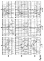
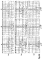
- FIG. 3 results from a first Sheet 3-I with the diagram lines 3.1 to 3.3 and a second sheet 3-II with the Diagram lines 3.4 to 3.6 are composed.
- the first diagram line 3.1 shows the normal sum signal which has a lower side lobe amplitude in the 45 ° plane according to column B than in the zx plane (column A) and in the zy plane (column C).
- the second line 3.2 shows the diagrams R HYPxz in the case of signal processing according to equation (9a) and line 3.3 the output direction finding signals R HYPyz according to equation (9b).
- P HYPyz shown in line 3.3, the situation is exactly the opposite.
- equation (12) compared to the normal sum signal (diagram line 3.1), there is now an improvement in the bundling and an increase in the sidelobe damping in all room levels (see Columns A, B, and C), while the directional characteristics in signal processing after the previous registration remain unaffected in the planes perpendicular to the main bundling planes.
- Directional diagram improvements are clearly shown in line 3.6, where both the bundling and the side lobe suppression are significantly improved.
- FIG. 4 shows an example of such a transducer arrangement in which two transducer group pairs are formed from the four transducer groups W LH , W LV , W RH and W RV , which are not oriented at right angles to one another.
- the main bundling planes here are the zx plane and a ⁇ z plane that is rotated by an angle ⁇ ⁇ 90 ° with respect to it and encloses the z axis.
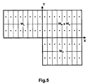
- two pairs of transducer groups can not only be formed from four transducer groups as previously described, but three identical transducer groups are sufficient for this.
- An example is shown in Fig. 5.
- the pairs of converter groups can be oriented at an angle ⁇ different from one another by 90 °.
- the application of the invention to a ship or submarine bearing on the side has the advantage that in addition to good focus sharpness in the optionally pivotable the main direction of the bearing also has a high side lobe suppression in the direction of travel including the plane, e.g. the screwing sound of your own Propeller does not affect the bearing.
- FIG. 6 A further embodiment of the invention is illustrated in FIG. 6.
- the ship is equipped here, for example, with a left converter group W L and a right converter group W R , which are oriented horizontally, that is, plumb down.
- Each transducer group consists of a plurality of transducer elements so that the main bearing direction can be pivoted in the transverse direction in a known manner by phase-staggered excitation and / or scanning.
- the two converter groups are arranged side by side in relation to the direction of travel F.
- a so-called synthetic aperture is first used, in which bearings along the travel path are carried out at predetermined spatial or temporal intervals ⁇ s or ⁇ t and the complex received signals Lsas and Rsas of the two converter groups W L and W R are temporarily stored.
- This known method in which the resulting aperture is considerably enlarged compared to the dimensions of the transducer arrangement and thus the bearing sharpness can be increased, is referred to as a sonar with a synthetic aperture SAS (Synthetic Aperture Sonar).
- the signals measured and buffered at certain path positions s i are then superimposed with a phase shift in order to generate a sharply bundled directional diagram in a plane including the direction of travel.
- the two complex output signals generated by SAS are used Lsas and Rsas of the left or right converter group combined analogously to equation (6), for example according to the following equation, to form a resulting output direction finding signal R HYPsas (n):
- the amount and phase of Lsas and Rsas available, ie the left and right SAS signals must be complex.
Landscapes
- Physics & Mathematics (AREA)
- Engineering & Computer Science (AREA)
- General Physics & Mathematics (AREA)
- Radar, Positioning & Navigation (AREA)
- Remote Sensing (AREA)
- Measurement Of Velocity Or Position Using Acoustic Or Ultrasonic Waves (AREA)
Applications Claiming Priority (2)
| Application Number | Priority Date | Filing Date | Title |
|---|---|---|---|
| DE1998122445 DE19822445A1 (de) | 1996-11-22 | 1998-05-19 | Verfahren zur räumlichen Richtstrahlbildung in Peilanlagen |
| DE19822445 | 1998-05-19 |
Publications (2)
| Publication Number | Publication Date |
|---|---|
| EP0959367A2 true EP0959367A2 (fr) | 1999-11-24 |
| EP0959367A3 EP0959367A3 (fr) | 2000-08-02 |
Family
ID=7868290
Family Applications (1)
| Application Number | Title | Priority Date | Filing Date |
|---|---|---|---|
| EP99109603A Withdrawn EP0959367A3 (fr) | 1998-05-19 | 1999-05-14 | Procédé de formation spatiale de faisceau hertzien dans des systèmes de repérage |
Country Status (2)
| Country | Link |
|---|---|
| US (1) | US6178140B1 (fr) |
| EP (1) | EP0959367A3 (fr) |
Cited By (1)
| Publication number | Priority date | Publication date | Assignee | Title |
|---|---|---|---|---|
| WO2010135465A1 (fr) * | 2009-05-19 | 2010-11-25 | Arsen Melconian | Systèmes et procédés permettant de suivre une source éloignée et de contrôler l'orientation |
Families Citing this family (15)
| Publication number | Priority date | Publication date | Assignee | Title |
|---|---|---|---|---|
| DE60232609D1 (de) * | 2002-08-30 | 2009-07-23 | Ericsson Telefon Ab L M | Verringerung von nah-mehrdeutigkeiten |
| WO2004021512A1 (fr) | 2002-08-30 | 2004-03-11 | Telefonaktiebolaget Lm Ericsson | Procede permettant d'augmenter la precision de mesure d'un reseau d'antennes |
| KR100689514B1 (ko) * | 2006-01-23 | 2007-03-02 | 주식회사 하이닉스반도체 | 반도체 소자 및 그의 제조 방법 |
| EP2756609B1 (fr) | 2011-09-15 | 2019-11-06 | Samsung Electronics Co., Ltd. | Appareil et procédé pour sélectionner un faisceau dans un système de communication sans fil à formation de faisceaux |
| US10177607B2 (en) | 2015-04-10 | 2019-01-08 | Ossia Inc. | Techniques for delivering retrodirective wireless power |
| US10256670B2 (en) | 2015-04-10 | 2019-04-09 | Ossia Inc. | Wireless power transceivers for supplementing wireless power delivery and extending range |
| US10079494B2 (en) | 2015-04-10 | 2018-09-18 | Ossia Inc. | Removably attachable portable device apparatus with integrated wireless power receiving facilities |
| US9971015B2 (en) | 2015-04-10 | 2018-05-15 | Ossia Inc. | Techniques for imaging wireless power delivery environments and tracking objects therein |
| US10193397B2 (en) | 2015-04-10 | 2019-01-29 | Ossia Inc. | Establishing connections with chargers in multi-charger wireless power delivery environments |
| US10559971B2 (en) | 2015-04-10 | 2020-02-11 | Ossia Inc. | Wirelessly chargeable battery apparatus |
| KR20180069034A (ko) | 2015-10-15 | 2018-06-22 | 오시아 인크. | 다중 경로 무선 전력 전달 환경에서 펄싱된 전송의 포커싱 |
| US11146093B2 (en) | 2017-03-31 | 2021-10-12 | Ossia Inc. | Actively modifying output voltage of a wirelessly chargeable energy storage apparatus |
| US10418861B2 (en) | 2017-12-22 | 2019-09-17 | Ossia Inc. | Transmission path identification based on propagation channel diversity |
| EP3809526A1 (fr) | 2019-10-18 | 2021-04-21 | Rohde & Schwarz GmbH & Co. KG | Système d'antenne et procédé de commande d'antenne |
| US12046910B2 (en) | 2020-02-24 | 2024-07-23 | Ossia Inc. | Devices and systems for providing wirelessly chargeable batteries with improved charge capacities |
Family Cites Families (4)
| Publication number | Priority date | Publication date | Assignee | Title |
|---|---|---|---|---|
| JPH0748616B2 (ja) | 1991-10-24 | 1995-05-24 | 宇宙開発事業団 | アンテナパターンの処理方法 |
| US5248984A (en) | 1991-11-13 | 1993-09-28 | National Space Development Agency Of Japan | Method for processing an antenna pattern |
| JPH06331720A (ja) * | 1993-05-26 | 1994-12-02 | Toyota Central Res & Dev Lab Inc | モノパルスアンテナ |
| DE19648327B4 (de) * | 1996-11-22 | 2004-03-18 | L-3 Communications Elac Nautik Gmbh | Verfahren zur Richtstrahlbildung in Peilanlagen und Vorrichtung zur Durchführung des Verfahrens |
-
1999
- 1999-03-24 US US09/275,650 patent/US6178140B1/en not_active Expired - Lifetime
- 1999-05-14 EP EP99109603A patent/EP0959367A3/fr not_active Withdrawn
Cited By (2)
| Publication number | Priority date | Publication date | Assignee | Title |
|---|---|---|---|---|
| WO2010135465A1 (fr) * | 2009-05-19 | 2010-11-25 | Arsen Melconian | Systèmes et procédés permettant de suivre une source éloignée et de contrôler l'orientation |
| US7999738B2 (en) | 2009-05-19 | 2011-08-16 | Arsen Melconian | Systems and methods for tracking a remote source and orientation control |
Also Published As
| Publication number | Publication date |
|---|---|
| US6178140B1 (en) | 2001-01-23 |
| EP0959367A3 (fr) | 2000-08-02 |
Similar Documents
| Publication | Publication Date | Title |
|---|---|---|
| EP0959367A2 (fr) | Procédé de formation spatiale de faisceau hertzien dans des systèmes de repérage | |
| DE2402050C3 (de) | Vorrichtung zur Verbesserung des Signal/Rauschabstands von Signalen, die von mehreren Antennen empfangen werden | |
| DE69930384T2 (de) | Adaptive gruppenantenne | |
| DE60302379T2 (de) | Radarverarbeitungssystem und Verfahren zur Erkennung und Überwachung von Zielen | |
| DE69402084T2 (de) | Sonarsystem für strömungsgeschwindigkeitmesser und dopplerlog | |
| DE102018210070A1 (de) | Verfahren zur Kalibrierung eines MIMO-Radarsensors für Kraftfahrzeuge | |
| DE69812783T2 (de) | Gruppenantenne mit Störungschutz | |
| DE3110532C2 (fr) | ||
| DE3411135C2 (de) | Phasengesteuertes Ultraschall-Abbildungssystem | |
| DE69022926T2 (de) | Virtuelle Mikrophonanlage und dafür bestimmtes Verfahren. | |
| DE69819273T2 (de) | Antenne gebildet durch eine Vielzahl von akustischen Detektoren | |
| DE2945830C2 (de) | Richtantennensystem für Freund-Feind-Identifizierung oder Peilung | |
| DE102013203789A1 (de) | Antennenanordnung mit veränderlicher Richtcharakteristik | |
| DE19648327B4 (de) | Verfahren zur Richtstrahlbildung in Peilanlagen und Vorrichtung zur Durchführung des Verfahrens | |
| EP2145203A1 (fr) | Procédé de relèvement d'une cible à rayonnement acoustique | |
| DE19627218B4 (de) | Radarvorrichtung | |
| WO2001091512A2 (fr) | Configuration de microphone directionnel et procede de traitement des signaux d'un telle configuration | |
| DE19503374B4 (de) | Passive Schallmeßwertwandleranordnung | |
| DE19822445A1 (de) | Verfahren zur räumlichen Richtstrahlbildung in Peilanlagen | |
| DE102010056526B4 (de) | Verfahren zum Bestimmen einer oder mehrerer relativer Richtungen als Zielpeilung oder Zielpeilungen sowie Vorrichtung zur Ausführung des Verfahrens | |
| DE10353292B3 (de) | Verfahren zur Bildung eines Gruppensignals | |
| EP3082273B1 (fr) | Procédé et dispositif de réduction de signaux parasites corrélés dans des systèmes de réception multi-canaux à formation de faisceau numérique | |
| DE4039153B4 (de) | Verfahren und Vorrichtung zur Erzeugung eines Strahlungsdiagramms im Ruhezustand bei einer Gruppenantenne | |
| DE60133222T2 (de) | Interferometische synthetische sonarantenne | |
| EP2145204B1 (fr) | Procédé de relèvement de cibles émettant des ondes sonores et dispositif de relèvement |
Legal Events
| Date | Code | Title | Description |
|---|---|---|---|
| PUAI | Public reference made under article 153(3) epc to a published international application that has entered the european phase |
Free format text: ORIGINAL CODE: 0009012 |
|
| AK | Designated contracting states |
Kind code of ref document: A2 Designated state(s): DE FR GB IT |
|
| AX | Request for extension of the european patent |
Free format text: AL;LT;LV;MK;RO;SI |
|
| PUAL | Search report despatched |
Free format text: ORIGINAL CODE: 0009013 |
|
| AK | Designated contracting states |
Kind code of ref document: A3 Designated state(s): AT BE CH CY DE DK ES FI FR GB GR IE IT LI LU MC NL PT SE |
|
| AX | Request for extension of the european patent |
Free format text: AL;LT;LV;MK;RO;SI |
|
| 17P | Request for examination filed |
Effective date: 20010118 |
|
| AKX | Designation fees paid |
Free format text: DE FR GB IT |
|
| 17Q | First examination report despatched |
Effective date: 20020410 |
|
| STAA | Information on the status of an ep patent application or granted ep patent |
Free format text: STATUS: THE APPLICATION HAS BEEN WITHDRAWN |
|
| 18W | Application withdrawn |
Effective date: 20021210 |