EP0959368A1 - Technique d'échantillonage de bande pour focalisation totale dans les systèmes d'imagerie à groupement de transducteurs - Google Patents
Technique d'échantillonage de bande pour focalisation totale dans les systèmes d'imagerie à groupement de transducteurs Download PDFInfo
- Publication number
- EP0959368A1 EP0959368A1 EP99112801A EP99112801A EP0959368A1 EP 0959368 A1 EP0959368 A1 EP 0959368A1 EP 99112801 A EP99112801 A EP 99112801A EP 99112801 A EP99112801 A EP 99112801A EP 0959368 A1 EP0959368 A1 EP 0959368A1
- Authority
- EP
- European Patent Office
- Prior art keywords
- signals
- signal
- imaging system
- ultrasonic
- output
- Prior art date
- Legal status (The legal status is an assumption and is not a legal conclusion. Google has not performed a legal analysis and makes no representation as to the accuracy of the status listed.)
- Granted
Links
Images
Classifications
-
- G—PHYSICS
- G10—MUSICAL INSTRUMENTS; ACOUSTICS
- G10K—SOUND-PRODUCING DEVICES; METHODS OR DEVICES FOR PROTECTING AGAINST, OR FOR DAMPING, NOISE OR OTHER ACOUSTIC WAVES IN GENERAL; ACOUSTICS NOT OTHERWISE PROVIDED FOR
- G10K11/00—Methods or devices for transmitting, conducting or directing sound in general; Methods or devices for protecting against, or for damping, noise or other acoustic waves in general
- G10K11/18—Methods or devices for transmitting, conducting or directing sound
- G10K11/26—Sound-focusing or directing, e.g. scanning
- G10K11/34—Sound-focusing or directing, e.g. scanning using electrical steering of transducer arrays, e.g. beam steering
- G10K11/341—Circuits therefor
- G10K11/345—Circuits therefor using energy switching from one active element to another
-
- G—PHYSICS
- G01—MEASURING; TESTING
- G01S—RADIO DIRECTION-FINDING; RADIO NAVIGATION; DETERMINING DISTANCE OR VELOCITY BY USE OF RADIO WAVES; LOCATING OR PRESENCE-DETECTING BY USE OF THE REFLECTION OR RERADIATION OF RADIO WAVES; ANALOGOUS ARRANGEMENTS USING OTHER WAVES
- G01S7/00—Details of systems according to groups G01S13/00, G01S15/00, G01S17/00
- G01S7/52—Details of systems according to groups G01S13/00, G01S15/00, G01S17/00 of systems according to group G01S15/00
- G01S7/52017—Details of systems according to groups G01S13/00, G01S15/00, G01S17/00 of systems according to group G01S15/00 particularly adapted to short-range imaging
- G01S7/52023—Details of receivers
- G01S7/52025—Details of receivers for pulse systems
- G01S7/52026—Extracting wanted echo signals
-
- G—PHYSICS
- G01—MEASURING; TESTING
- G01N—INVESTIGATING OR ANALYSING MATERIALS BY DETERMINING THEIR CHEMICAL OR PHYSICAL PROPERTIES
- G01N2291/00—Indexing codes associated with group G01N29/00
- G01N2291/04—Wave modes and trajectories
- G01N2291/044—Internal reflections (echoes), e.g. on walls or defects
-
- G—PHYSICS
- G01—MEASURING; TESTING
- G01S—RADIO DIRECTION-FINDING; RADIO NAVIGATION; DETERMINING DISTANCE OR VELOCITY BY USE OF RADIO WAVES; LOCATING OR PRESENCE-DETECTING BY USE OF THE REFLECTION OR RERADIATION OF RADIO WAVES; ANALOGOUS ARRANGEMENTS USING OTHER WAVES
- G01S7/00—Details of systems according to groups G01S13/00, G01S15/00, G01S17/00
- G01S7/52—Details of systems according to groups G01S13/00, G01S15/00, G01S17/00 of systems according to group G01S15/00
- G01S7/52017—Details of systems according to groups G01S13/00, G01S15/00, G01S17/00 of systems according to group G01S15/00 particularly adapted to short-range imaging
- G01S7/52046—Techniques for image enhancement involving transmitter or receiver
Definitions
- the present invention relates to an array imaging system, and more praticularly to an ultrasonic array imaging system in which ultrasonic echoes reflected from an object to be imaged and received by an array transducer, are focused in a digital fashion by applying one of the bandwidth sampling technique.
- an ultrasonic pulse signal is transmitted toward an object to be imaged, reflected from a surface of acoustic impedance discontinuity of the object, and received by an array transducer.
- the received signals are then converted into electric signals which are displayed on a video monitor after various processing.
- the resulting image conveys some information of the characteristics of the object being examined.
- the use of a short pulse is to increase the signal resolution and the use of an array is to obtain focusing capability to improve the lateral resolution.
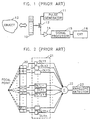
- FIG.1 is a schematic block diagram of a conventional ultrasonic imaging system.
- An ultrasonic pulse signal generated from a pulse generator 11 is supplied to an array transducer 10 via switch 12.
- the array transducer 10 converts an electric pulse signal into an ultrasonic signal and provides the converted signal to an object 13 to be imaged. Then, the ultrasonic signal is reflected from an acoustic impedance discontinuous surface of the object 13 and the reflected signal is again received by the array transducer 10. At this time, in the case that there are a plurality of acoustic impedance discontinuous surfaces, the ultrasonic signal is in turn reflected from each of discontinuous surfaces and is supplied to numbers of transducer elements.
- the array transducer 10 is composed of a plurality of transducer elements.
- the ultrasonic signal supplied to the array transducer 10 is converted by transducer elements into an electric signal with magnitude proportional to an intensity of the ultrasonic signal.
- the electric signal is amplified to the predetermined magnitude in an amplifier 14 via switch 12, processed to a video signal in a signal processor 15, and transmitted to a cathod ray tube (CRT) 16.
- CRT cathod ray tube
- the array transducer of a probe is composed of a plurality of transducer elements to be in the array form.
- This array form improves the resolution of a picture to be displayed with focusing an ultrasonic signal.
- Ultrasonic signals which are reflected from the object and supplied to the array transducer, have differently reach time to the transducer elements according to the positions of respective transducer elements. That is, the farther their positions are from the middle of the array transducer 10, the more reach time increases.
- FIG. 2 illustrates one embodiment of a conventional receiving focusing device of an ultrasonic signal.
- the device of FIG. 2 utilizes analog delayers.
- An array transducer 20 is composed, of n transducer elements in numbers, in which receiving signals converted into electric signals by each of transducer elements are supplied to n delayers DLY1 ⁇ DLYn, respectively.
- each of delayers DLY1 ⁇ DLYn allows the longest delay time to an input signal of the middle transducer element with the shortest reach time and permits the shortest delay time to input signals of first and n transducer elements with the longest reach time. Therefore, the delayers DLY1 ⁇ DLYn simultaneously output the delayed signals therein to an adder 22.
- the signals output from the respective delayers are added in the adder 22 and outputted as a focusing signal.
- the conventional device of FIG. 2 connects the delayers, having a predetermined delay time value, to output terminals of each of transducer elements and delays the output signal from the transducer elements.
- each of delayers DLY1 ⁇ DLYn compensates for differences of reach time to the transducer elements of the ultrasonic signals reflected from the object.
- An output signal from the adder 22 is supplied to an envelope detector 23.
- the conventional device of FIG. 2 employs a plurality of taps in delayers, and then a system of the device comes to be complicated in hardware.
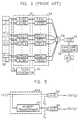
- FIG. 3 illustrates another embodiment of a conventional receiving focusing device of an ultrasonic signal.
- the device of FIG. 3 is called pipelined sampled delay focusing (PSDF).
- PSDF pipelined sampled delay focusing
- an array transducer 30 is composed of n transducer elements in numbers. Received ultrasonic signals are converted into electric signals by each of transducer elements. The electric signals output from transducer elements of the array transducer 30 are respectively supplied to n analog to digital converters A/D1 ⁇ A/Dn of an analog to digital converting unit 31.
- a clock generator 32 generates sampling clocks of a freqency "fs".
- the A/D converting unit 31 converts each of electric signals which are input from the transducer elements according to the sampling clock into digital signals, and supplies the converted signal to memories FIFO1 ⁇ FIFOn, respectively.
- the sampling clock of the clock generator 32 is not a uniform clock, but a variable sampling clock. That is, in the case of the dynamic focusing, the reach time of the ultrasonic signal is different from each other according to positions of each focal point.
- Output terminals of the A/D converting unit 31 are connected to a momory unit 33 composed of first-in-first-out memories FIFO1 ⁇ FIFOn. Output data of the A/D converting unit 31 is arranged within the memory unit 33, to be output in input order.
- the ultrasonic signals which are reflected from a particular focal point and supplied to transducer elements, can be simultaneously output from the memory unit 33.
- data is simultaneously output from the memory unit 33.
- the output data is added in an adder 34, and then dynamic focusing is performed.
- the focused ultrasonic signal is converted into an analog signal by digital-to-analog converter 35 and the converted signal is supplied to an envelope detector 36.
- the envelope detector 36 detects an envelope from the input signal, and an analog-to-digital converter 37 converts the detected envelope into a digital signal.
- the conventional device can obtain the best resolution by focusing an ultrasonic signal on all focal points requiring the dynamic focusing.
- the level of a sampling frequency becomes high because the A/D converting unit 31 samples a radio frequency signal.
- a sampling frequency is required beyond 28MHz. Therefore, there is a problem of occurrence of system noise due to high sampling frequencies of A/D conversion.
- a problem with relatively expensive costs is encounted because both memories and peripheral circuits with the device of high speed should be employed.
- a final signal required in an ultrasonic video device is an envelope of a focused RF signal, not the focused RF signal, the detection of the envelope should be executed.
- the present invention lowers the frequency band of output signals from transducer elements using bandwidth sampling methods. Signals with low frequency band are converted into digital signals by A/D conversion using a sampling frequency beyond the bandwidth. The converted digital signals are focused through memory, and then envelope data of each of focal points is detected by an envelope detector.
- Embodiments of the present invention disclose both an analytic signal sampling using the Hilbert transform of the bandwidth sampling methods and a quadrature sampling. A quadrature sampling method discloses the compensation of phase errors.
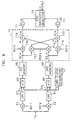
- FIG. 4 illustrates one preferred embodiment of an ultrasonic imaging system for focusing a digital signal in accordance with the present invention.
- an array transducer 40 is composed of n transducer elements in numbers. Each of output terminals of the transducer elements is connected to each of input terminals of phase transformers PDN1 ⁇ PDNn within a band transformer 41. Each of output terminals of the band transformer 41 is connected to input terminals of an analog to digital converting unit 42, respectively.
- the A/D converting unit 42 receives sampling frequencies f s from a first clock generator 43 and converts the received signal into a digital signal, and then the digital signal is stored in a memory unit 44.
- the A/D converting unit 42 and the first clock generator 43 include a delayed-time difference eliminator for which compensates for the differences of delay time between a plurality of ultrasonic signals relating to a particular focal point.
- the memory unit 44 simultaneously outputs the stored data to an adding unit 45.
- the adding unit 45 includes first and second adders 46 and 47.
- An envelope detector 48 coupled to outputs of the first and second adder 46 and 47, detects an envelope of the focused signal.
- FIG. 5 illustrates one of phase transformers and A/D converters in the system of FIG. 4.
- the system of FIG. 5 embodies an analytic signal sampling, one of bandwidth sampling methods.
- An analytic signal sampling method can easily obtain a desired envelope by utilizing both Hilbert transform and A/D conversion in which a sampling frequency is beyond signal bandwidth.
- the analytic signal sampling method can be written as follows.
- an analytic signal X A(t) is, as the equation (1), represented by complex adding of the two signal.
- X A ( t ) U ( t ) + jV ( t )
- the Fourier transform of a signal to which the Hilbert transform may be carried out has the following characteristic. Due to the Fourier transform characteristic in the Hilbert transform by the equation (2), the Fourier transform of the analytic signal X A ( t ) of the equation (1) is as follows. As shown in the equation (3), a negative frequency term in the analytic signal X A ( t ) is removed by Fourier transform. Accordingly, if the sampling frequency f s is maintained beyond the bandwidth of an input signal [see the equation (4)], aliasing will not come to happen.
- FIG. 5 illustrates a procedure that an output signal U(t) from one transducer element is supplied to a phase transformer 41A.
- a Hilbert transformer 51 included in the phase transformer 41A Hilbert-transforms the input signal U(t) and generates a signal V(t).
- the signal U(t) and the signal V(t) output from the phase transformer 41A are separately provided to a first A/D converter 52 and a second A/D converter 53.
- the first and second A/D converters 52 and 53 sample the input signals into a sampling frequency satisfactory to the above equation (4). Accordingly, the output signals of the first and second A/D converters 52 and 53 respectively become signals U(kT s ) and V(kT s ) represented by the equations (6) and (7), wherein kT s of the signal means k sampling.
- the system of FIG. 4 shows that an analytic signal sampling method is applied to an ultrasonic signal focusing.
- the array transducer 40 transforms a plurality of reflected and received ultrasonic signals into electric signals. Then, the ultrasonic signal provided to "j" transducer element of the array transducer 40 needs different delay time according to positions of the transducer elements.
- the signal U(t) expressed by the equation (6) can be denoted as the equation (9) including delay time.
- the signal of U j ( t - ⁇ j ) represented as the equation (9) has a quadrature difference by the array transducer 41, that is, the signal becomes a Hilbert-transformed signal of V j ( t - ⁇ j ).
- V j ( t - ⁇ j ) A jQ ( t - ⁇ j )cos ⁇ o ( t - ⁇ j ) + A jI ( t - ⁇ j )sin ⁇ o ( t - ⁇ j )
- U j ( t - ⁇ j ) and V j ( t - ⁇ j ) represented by the equations (9) and (10) are applied to a focusing method using a conventional analog delayer is as follows.
- T s a reciprocal of "T s ", that is, a sampling frequency should be maintained beyond the bandwidth of an input signal.
- " ⁇ (t-(kT s -d jk ))" is set as a variable sampling clock necessary to a digital focusing method of the ultrasonic signal.
- the first clock generator 43 generates variable sampling clocks suitable for delay time varying according to focal points. As a result, the first clock generator 43 supplies different sampling time to pairs of A/D converters corresponding to each of the transducer elements, in order to compensate for the differences of delay time in signals supplied to each of the transducer elements.
- the signals of U jk and V jk sampled by the A/D converting unit 42 are supplied to the memory unit 44.
- the memory unit 44 When initial data with respect to a particular focal point is supplied to the memory unit 44, the memory unit 44 stores the input data until the maximum delay time to the focal point goes by. After the lapse of the maximum delay time, the memory unit 44 outputs, in order, the stored data to an adding unit 45. The adding unit 45 adds and outputs the input data.
- the signals of U k and V k focused on "k" focal point by a first adder 46 and a second adder 47 are represented by the equations (15) and (16).
- U k is a focusing signal of "k" focal point added in the
- a first envelope detector 48 calculates the signals added in the adding unit 45 by the equation (17) and generates envelope data A k with the result of calculation.
- envelope data means amplitude of a signal
- equation (17) corresponds to the envelope data of "k" focal point.
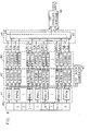
- FIG. 6 illustrates another preferred embodiment of an ultrasonic imaging system for focusing a digital signal in accordance with the present invention.
- FIG. 6 like FIG. 4, relates to a focusing system of an ultrasonic signal received through an array transducer (not shown) composed of n transducer elements in numbers.
- the system of FIG. 6 shows only the focusing of an ultrasonic signal being input through any one of transducer elements because the same procedure for focusing may be applied to each of n ultrasonic signals transformed into electric signals.
- the system of FIG. 6 includes a frequency band transformer composed of a multiply 61 or 62 and low pass filter 63 or 64.
- first and second A/D converters 65 and 66, and a second clock generator 67 include a delayed-time difference eliminator.
- An output signal (U j ) of the "j" transducer element is supplied to the first multiply 61 and the second multiply 62.
- Either first multiply 61 or second multiply 62 multiplies an output signal of the transducer element with a first reference signal REF1 or a second reference signal REF2, and supplies the multiplied value to a first low pass filter 63 or a second low pass filter 64.
- Output terminals of the first and second low pass filters 63 and 64 are connected to input terminals of the first and second A/D converters 65 and 66, respectively.
- the first and second A/D converters 65 and 66 convert the input signal into a digital signal according to a sampling frequency f s supplied from the second clock generator 67, and outputs the converted signal to first and second memories 68 and 69.
- the first and second memories 68 and 69 store the output from the A/D converter, and output the stored data.
- a phase compensator 70 includes third through sixth multiplies 710 ⁇ 716 which multiply the output signal from the first and second memories 68 and 69 by a third reference signal REF3 or a fourth reference signal REF4, a subtracter 718 which subtracts the output of a fifth multiply 714 from that of a third multiply 710, and a third adder 720 which adds the output of fourth and sixth multiplies 712 and 716.
- the output of the phase compensator 70 is supplied to fourth and fifth adders 71 and 72.
- the fourth and fifth adders 71 and 72 sum output signals of all the phase compensators corresponding to a predetermined number of transducer elements (not shown), and supply the summed value to a second envelope detector 73.
- FIG. 6 Such a preferred embodiment of FIG. 6 relates to the focusing system of an ultrasonic signal using a quadrature sampling method, one of bandwidth sampling methods, and the operation will be described in detail.
- the quadrature sampling method moves reflected ultrasonic signals from radio frequency (RF) band to baseband using a predetermined number of multiplies and low pass filters, and samples them. Accordingly, it is advantageous that the envelope of reflected ultrasonic signals can be easily obtained if a sampling frequency comes to be maintained beyond the bandwidth of reflected ultrasonic signals.
- RF radio frequency
- a I (t) is an inphase term of the signal U(t)
- a Q (t) is a quadrature term of X(t).
- ⁇ j means delay time of the "j" transducer element of transducer elements being in the middle of the array transducer.
- Such a reflected ultrasonic signal U j is supplied to the first multiply 61 and multiplied by a first reference signal REF1 of " cos ⁇ r t ", and at the same time is supplied to the second multiply 62 and multiplied by a second reference signal REF2 of " sin ⁇ r t ".
- ⁇ r is a reference frequency utilizing in the first and second multiplies 61 and 62.
- the signals, which are multiplied by each of reference signals in the first and second multipliers 61 and 62, have no high frequency components through the first and second low pass filters 63 and 64, and are expressed by the equations (20) and (21).
- I 1 j U j ( t - ⁇ i )cos ⁇ r t
- LPF 1 2 A jI ( t - ⁇ j )cos[( ⁇ o - ⁇ r ) t - ⁇ o ⁇ j ] - 1 2 A jQ ( t - ⁇ j )sin[( ⁇ o - ⁇ r ) t - ⁇ 0 ⁇ j ])
- Q 1 j X j ( t - ⁇ i )sin ⁇ r t
- LPF 1 2 A jI ( t - ⁇ j )sin[( ⁇ o - ⁇ r ) t - ⁇ o ⁇ j ] - 1 2 A jQ ( t - ⁇ j )cos[( ⁇ 0 - ⁇ r ) t - ⁇ 0 ⁇ j ]
- high frequency components that is, an frequency addition term of "( ⁇ 0
- the two signals (I1 j , Q1 j ) represented by the quations (20) and (21) are separately supplied to the first and second A/D converters 65 and 66.
- the first and second A/D converters 65 and 66 sample the input signal according to the sampling frequency f s supplied from the second clock generator 67.
- the second clock generator 67 generates a sampling clock of the sampling frequency f s more than the bandwidth of reflected and received ultrasonic signals.
- the second clock generator 67 like the first clock generator 43 of FIG.
- pairs of A/D converters corresponding to each of the transducer elements output the digital signals in which the differences of the delay time occurring between signals received from the array transducer are compensated.
- the first and second A/D converters 65 and 66 output the digital signals obtained through sampling to the first and second memories 68 and 69.
- Memories (not shown) corresponding to other transducer elements as well as the memories 68 and 69 corresponding to the "j" transducer element, in the case that initial data with respect to a particular focal point is input therein, store the input data until the maximum delay time of the focal point goes by. After the lapse of the maximum delay time, the memories output, in order, the stored data to the adding unit 45.
- a signal I2 jk supplied from the first memory 68 to the third and fourth multiplies 710 and 712, and a signal Q2 jk supplied from the second memory 69 to the fifth and sixth multiplies 714 and 716 are as follows.
- the "m jk” should be selected to be " m jk T s ⁇ j ".
- Envelope data is compensated from the differences between delay times by adding either a signal I k or a signal Q k with respect to all the transducer elements in order to obtain envelope data at "k” focal point.
- ⁇ r m jk T s " included in phase terms has differently "m jk " per all the transducer elements, errors by phase difference may happen.
- the present invention includes the phase compensator 70, connected between memories and adders, for compensating phase errors.
- the equations (22) and (23) can be simply represented as follows.
- I 2 jk B jI ( k )cos( ⁇ + ⁇ jk )- B jQ ( k )sin( ⁇ + ⁇ jk )
- Q 2 jk - B jI ( k )sin( ⁇ + ⁇ jk )- B jQ ( k )cos( ⁇ + ⁇ jk )
- ⁇ jk - ⁇ r m jk T s " utilized for the phase compensation, since " ⁇ r " and "T s " are known values, "m jk " is a variable according to focal points but can be anticipated, and " ⁇ jk " can be calculated by previously known values ( ⁇ r , T s , m jk ).
- the phase compensation is possible by using a " ⁇ jk” value added to the third and fourth reference signals REF3 and REF4 which are supplied to the third to sixth multiplies 710 ⁇ 716.
- the third multiply 710 multiplies a signal I2 jk supplied from the first memory 68 and the third reference signal REF3 of " cos ⁇ jk ", and outputs the multiplied value to a subtracter 718.
- the fourth multiply 712 multiplies the signal I2 jk supplied from the first memory 68 and the fourth reference signal REF4 of " sin ⁇ jk " and outputs the multiplied value to a third adder 720.
- the fifth multiply 714 multiplies a signal Q2 jk supplied from the second memory 69 and the fourth reference signal REF4 of " sin ⁇ jk ", and outputs the multiplied value to the subtracter 718.
- the sixth multiply 716 multiplies the signal Q2 jk supplied from the second memory 69 and the third reference signal REF3 of " cos ⁇ jk ", and outputs the multiplied value to the third adder 720.
- the subtracter 718 subtracts an output signal of the fifth multiply 714 from an output singal of the third multiply 710, and outputs the subtracted value to the fourth adder 71.
- the third adder 720 adds output signals of the fourth and sixth multiplies 712 and 716, and outputs the added value to the fifth adder 72.
- the output signals I jk and Q jk of the subtracter 718 and third adder 720 have no the phase errors ⁇ jk by means of the computation of third to sixth multiplies 710 ⁇ 716, subtracter 718 and third adder 720, which is represented by the following equations.
- the signals in which phase errors are removed by the phase compensator 70 are added to each of output singals of phase compensators (not shown) corresponding to other transducer elements in the fourth and fifth adders 71 and 72, and are focused as follows.
- a second envelope detector 73 which receives two components of inphase and quadrature focused as the equations (32) and (33), detects an envelope "A(kT s )" according to the equation (34).
- a ( kT s ) ( I 2 k + Q 2 k ) 1/2
- a digital focusing method and system in accordance with the present invention even if an ultrasonic signal is focused by the digital method, solves a high sampling frequency and the difficulty of envelope detection in a digital process, using both analytic signal sampling and quadrature sampling among bandwidth sampling methods.
- the present invention reduces complexity of a focusing system and makes dynamic focusing possible, and thereby has an effect on easiness of the envelope detection.
- An ultrasonic can be utilized in a medical diagnosis, non-destruction inspection, underwater investigation, etc.
- the present invention can be applied to imaging systems using any type of array transducers including linear, phased, convex, concave and annular arrays.
- the present invention can be applied not only to ultrasonic imaging systems but also to radar systems using array transducers for the beam forming purpose.
- the present invention can be applied to any imaging modelity in which the analytic signal can be effectively utilized, including B, C and M mode images, for flow measurement, phase aberration correction, tissue characterization, etc.
Landscapes
- Engineering & Computer Science (AREA)
- Physics & Mathematics (AREA)
- Acoustics & Sound (AREA)
- Multimedia (AREA)
- Computer Networks & Wireless Communication (AREA)
- General Physics & Mathematics (AREA)
- Radar, Positioning & Navigation (AREA)
- Remote Sensing (AREA)
- Investigating Or Analyzing Materials By The Use Of Ultrasonic Waves (AREA)
- Ultra Sonic Daignosis Equipment (AREA)
- Measurement Of Velocity Or Position Using Acoustic Or Ultrasonic Waves (AREA)
Applications Claiming Priority (3)
| Application Number | Priority Date | Filing Date | Title |
|---|---|---|---|
| KR9308944 | 1993-05-24 | ||
| KR1019930008944A KR950013122B1 (ko) | 1993-05-24 | 1993-05-24 | 초음파신호의 디지탈집속방법 및 그 장치 |
| EP94915699A EP0657034A1 (fr) | 1993-05-24 | 1994-05-23 | Technique d'echantillonnage de largeur de bande pour focalisation digitale dans les systemes d'imagerie a groupement de transducteurs |
Related Parent Applications (1)
| Application Number | Title | Priority Date | Filing Date |
|---|---|---|---|
| EP94915699A Division EP0657034A1 (fr) | 1993-05-24 | 1994-05-23 | Technique d'echantillonnage de largeur de bande pour focalisation digitale dans les systemes d'imagerie a groupement de transducteurs |
Publications (2)
| Publication Number | Publication Date |
|---|---|
| EP0959368A1 true EP0959368A1 (fr) | 1999-11-24 |
| EP0959368B1 EP0959368B1 (fr) | 2008-11-05 |
Family
ID=19355905
Family Applications (2)
| Application Number | Title | Priority Date | Filing Date |
|---|---|---|---|
| EP94915699A Withdrawn EP0657034A1 (fr) | 1993-05-24 | 1994-05-23 | Technique d'echantillonnage de largeur de bande pour focalisation digitale dans les systemes d'imagerie a groupement de transducteurs |
| EP99112801A Expired - Lifetime EP0959368B1 (fr) | 1993-05-24 | 1994-05-23 | Technique d'échantillonage de bande pour focalisation totale dans les systèmes d'imagerie à groupement de transducteurs |
Family Applications Before (1)
| Application Number | Title | Priority Date | Filing Date |
|---|---|---|---|
| EP94915699A Withdrawn EP0657034A1 (fr) | 1993-05-24 | 1994-05-23 | Technique d'echantillonnage de largeur de bande pour focalisation digitale dans les systemes d'imagerie a groupement de transducteurs |
Country Status (6)
| Country | Link |
|---|---|
| US (1) | US5581036A (fr) |
| EP (2) | EP0657034A1 (fr) |
| JP (1) | JP2728183B2 (fr) |
| KR (1) | KR950013122B1 (fr) |
| DE (1) | DE69435164D1 (fr) |
| WO (1) | WO1994028467A1 (fr) |
Families Citing this family (14)
| Publication number | Priority date | Publication date | Assignee | Title |
|---|---|---|---|---|
| EP0736965A1 (fr) * | 1995-04-04 | 1996-10-09 | Medison Co., Ltd. | Méthode et appareil pour le démodulation des signaux utilisant l'échantillonage multiple |
| US6535610B1 (en) * | 1996-02-07 | 2003-03-18 | Morgan Stanley & Co. Incorporated | Directional microphone utilizing spaced apart omni-directional microphones |
| US7580488B2 (en) | 2000-11-29 | 2009-08-25 | The Penn State Research Foundation | Broadband modulation/demodulation apparatus and a method thereof |
| US20040167396A1 (en) * | 2003-02-25 | 2004-08-26 | The Regents Of The University Of California | Quantitative full aperture tomography imaging system and method |
| AU2003218048A1 (en) * | 2003-03-07 | 2004-09-30 | The Penn State Research Foundation | A broadband modulation/demodulation apparatus and a method thereof |
| ES2277473B1 (es) * | 2004-01-30 | 2008-07-16 | Consejo Sup. Investig. Cientificas | Composicion coherente de señales por correccion focal progresiva. |
| US8220334B2 (en) | 2006-11-10 | 2012-07-17 | Penrith Corporation | Transducer array imaging system |
| US20080114246A1 (en) * | 2006-11-10 | 2008-05-15 | Penrith Corporation | Transducer array imaging system |
| US9295444B2 (en) * | 2006-11-10 | 2016-03-29 | Siemens Medical Solutions Usa, Inc. | Transducer array imaging system |
| JP6053339B2 (ja) * | 2012-06-06 | 2016-12-27 | キヤノン株式会社 | 被検体情報取得装置および被検体情報取得方法 |
| US9248221B2 (en) | 2014-04-08 | 2016-02-02 | Incuvate, Llc | Aspiration monitoring system and method |
| US10405829B2 (en) | 2014-12-01 | 2019-09-10 | Clarius Mobile Health Corp. | Ultrasound machine having scalable receive beamformer architecture comprising multiple beamformers with common coefficient generator and related methods |
| GB2533388B (en) | 2014-12-17 | 2021-01-06 | Sezanne Marine Ltd | Aspects of a sonar system |
| CN107889001B (zh) * | 2017-09-29 | 2020-02-18 | 恒玄科技(上海)股份有限公司 | 可扩展麦克风阵列及其建立方法 |
Citations (2)
| Publication number | Priority date | Publication date | Assignee | Title |
|---|---|---|---|---|
| US4290127A (en) * | 1979-12-03 | 1981-09-15 | Raytheon Company | Beamformer with reduced sampling rate |
| US4837578A (en) * | 1981-10-29 | 1989-06-06 | California Institute Of Technology | Apparatus and method for range detection using the analytic signal identified from the received signal |
Family Cites Families (21)
| Publication number | Priority date | Publication date | Assignee | Title |
|---|---|---|---|---|
| US4241610A (en) * | 1979-02-05 | 1980-12-30 | Varian Associates, Inc. | Ultrasonic imaging system utilizing dynamic and pseudo-dynamic focusing |
| DE3020872A1 (de) * | 1980-06-02 | 1981-12-10 | Siemens AG, 1000 Berlin und 8000 München | Vorrichtung zur ultraschall-abtastung |
| US4324258A (en) * | 1980-06-24 | 1982-04-13 | Werner Huebscher | Ultrasonic doppler flowmeters |
| GB2127992B (en) * | 1982-09-28 | 1986-04-16 | Audim Sa | Cross-correlator |
| JPS5994092A (ja) * | 1982-11-20 | 1984-05-30 | Toshiba Corp | 開口合成法に基づく信号処理装置 |
| US4679176A (en) * | 1983-11-24 | 1987-07-07 | Hitachi, Ltd. | Ultrasonic receiving apparatus |
| US4553437A (en) * | 1984-01-30 | 1985-11-19 | Imaging Associates | Hybrid non-invasive ultrasonic imaging system |
| DE3428046A1 (de) * | 1984-07-30 | 1986-01-30 | Siemens AG, 1000 Berlin und 8000 München | Verfahren und vorrichtung zur verzoegerung eines ultraschallsignals |
| CA1232059A (fr) * | 1985-03-21 | 1988-01-26 | Donald C. Knudsen | Controleur de retard numerique pour generateurs de signaux sonar et radar |
| GB2176356A (en) * | 1985-06-12 | 1986-12-17 | Philips Electronic Associated | Method of, and demodulator for, digitally demodulating an ssb signal |
| NL8600444A (nl) * | 1986-02-21 | 1987-09-16 | Optische Ind De Oude Delft Nv | Inrichting voor ultrageluiddetectie. |
| US5235857A (en) * | 1986-05-02 | 1993-08-17 | Forrest Anderson | Real time 3D imaging device using filtered ellipsoidal backprojection with extended transmitters |
| US5005419A (en) * | 1988-06-16 | 1991-04-09 | General Electric Company | Method and apparatus for coherent imaging system |
| DE3829370A1 (de) * | 1988-08-30 | 1990-03-01 | Kabelmetal Electro Gmbh | Doppelerreger fuer spiegelantennen zur erzeugung zweier eng benachbarter strahlungskeulen |
| DE3830729C2 (de) * | 1988-09-09 | 1998-04-09 | Hagenuk Marinekommunikation Gm | Verfahren zum Erzeugen eines Einseitenbandsignals und Schaltungsanordnung zur Durchführung des Verfahrens |
| US4974211A (en) * | 1989-03-17 | 1990-11-27 | Hewlett-Packard Company | Digital ultrasound system with dynamic focus |
| US5065763A (en) * | 1990-02-21 | 1991-11-19 | Sri International | Combined reflection and transmssion untrasonic imaging method and apparatus |
| US5103427A (en) * | 1990-05-22 | 1992-04-07 | The University Of Akron | Method and apparatus generating high resolution data and echo identification |
| JPH0595951A (ja) * | 1991-03-08 | 1993-04-20 | Fujitsu Ltd | 超音波影像装置 |
| US5235983A (en) * | 1991-03-08 | 1993-08-17 | Fujitsu Limited | Ultrasonic imaging apparatus |
| US5197037A (en) * | 1991-10-31 | 1993-03-23 | Hewlett-Packard Company | Method and apparatus for the simultaneous performance of the beam formation and scan conversion in a phased array system |
-
1993
- 1993-05-24 KR KR1019930008944A patent/KR950013122B1/ko not_active Expired - Lifetime
-
1994
- 1994-05-23 WO PCT/KR1994/000055 patent/WO1994028467A1/fr not_active Ceased
- 1994-05-23 EP EP94915699A patent/EP0657034A1/fr not_active Withdrawn
- 1994-05-23 DE DE69435164T patent/DE69435164D1/de not_active Expired - Lifetime
- 1994-05-23 EP EP99112801A patent/EP0959368B1/fr not_active Expired - Lifetime
- 1994-05-23 US US08/367,281 patent/US5581036A/en not_active Expired - Lifetime
- 1994-05-23 JP JP7500490A patent/JP2728183B2/ja not_active Expired - Lifetime
Patent Citations (2)
| Publication number | Priority date | Publication date | Assignee | Title |
|---|---|---|---|---|
| US4290127A (en) * | 1979-12-03 | 1981-09-15 | Raytheon Company | Beamformer with reduced sampling rate |
| US4837578A (en) * | 1981-10-29 | 1989-06-06 | California Institute Of Technology | Apparatus and method for range detection using the analytic signal identified from the received signal |
Non-Patent Citations (6)
| Title |
|---|
| CASTELLINI G ET AL: "REAL-TIME DIGITAL DYNAMIC FOCUSING SYSTEM", ULTRASONICS, vol. 28, no. 2, 1 March 1990 (1990-03-01), pages 124 - 126, XP000115773, ISSN: 0041-624X * |
| JOO HAN KIM ET AL: "Pipelined sampled-delay focusing in ultrasound imaging systems", ULTRASONIC IMAGING, APRIL 1987, USA, vol. 9, no. 2, pages 75 - 91, XP002113987, ISSN: 0161-7346 * |
| MUCCI R A: "A COMPARISON OF EFFICIENT BEAMFORMING ALGORITHMS", IEEE TRANSACTIONS ON ACOUSTICS, SPEECH AND SIGNAL PROCESSING, vol. ASSP-32, no. 3, 1 June 1984 (1984-06-01), pages 548 - 558, XP002030176 * |
| PRIDHAM R G ET AL: "Digital interpolation beamforming for low-pass and bandpass signals", PROCEEDINGS OF THE IEEE, JUNE 1979, USA, vol. 67, no. 6, pages 904 - 919, XP002113988, ISSN: 0018-9219 * |
| SEONG HO CHANG ET AL: "PHASE-ERROR-FREE QUADRATURE SAMPLING TECHNIQUE IN THE ULTRASONIC B -SCAN IMAGING SYSTEM AND ITS APPLICATION TO THE SYNTHETIC FOCUSING SYSTEM", IEEE TRANSACTIONS ON ULTRASONICS, FERROELECTRICS AND FREQUENCY CONTROL, vol. 40, no. 3, 1 May 1993 (1993-05-01), pages 216 - 223, XP000382840, ISSN: 0885-3010 * |
| TAI K SONG ET AL: "A NEW DIGITAL PHASED ARRAY SYSTEM FOR DYNAMIC FOCUSING AND STEERING WITH REDUCED SAMPLING RATE", ULTRASONIC IMAGING, vol. 12, no. 1, 1 January 1990 (1990-01-01), pages 1 - 16, XP000125528, ISSN: 0161-7346 * |
Also Published As
| Publication number | Publication date |
|---|---|
| KR950013122B1 (ko) | 1995-10-25 |
| JPH07509786A (ja) | 1995-10-26 |
| US5581036A (en) | 1996-12-03 |
| JP2728183B2 (ja) | 1998-03-18 |
| EP0959368B1 (fr) | 2008-11-05 |
| WO1994028467A1 (fr) | 1994-12-08 |
| DE69435164D1 (de) | 2008-12-18 |
| EP0657034A1 (fr) | 1995-06-14 |
Similar Documents
| Publication | Publication Date | Title |
|---|---|---|
| EP0959368A1 (fr) | Technique d'échantillonage de bande pour focalisation totale dans les systèmes d'imagerie à groupement de transducteurs | |
| US5431167A (en) | Method and apparatus for increasing the frame rate and resolution of a phased-array imaging system | |
| US5369624A (en) | Digital beamformer having multi-phase parallel processing | |
| US6454714B1 (en) | Ultrasonic harmonic flash suppression | |
| Kim et al. | Pipelined sampled-delay focusing in ultrasound imaging systems | |
| JP4177955B2 (ja) | 超音波診断装置及び超音波信号の処理方法 | |
| US4817617A (en) | Diagnostic imaging apparatus | |
| US6514205B1 (en) | Medical digital ultrasonic imaging apparatus capable of storing and reusing radio-frequency (RF) ultrasound pulse echoes | |
| US5388079A (en) | Partial beamforming | |
| US4800891A (en) | Doppler velocity processing method and apparatus | |
| JP4039642B2 (ja) | 超音波ビーム形成装置 | |
| US5706818A (en) | Ultrasonic diagnosing apparatus | |
| JPH01207042A (ja) | 位相収差効果の反復適応形減少方法と装置 | |
| JPH10507099A (ja) | 受信ビーム生成器システムにおけるベースバンド・プロセッサのための方法及び装置 | |
| US5188112A (en) | Ultrasonic Doppler imaging systems with improved flow sensitivity | |
| US5063541A (en) | Beam forming method and apparatus therefor in ultrasonic imaging system | |
| US6624783B1 (en) | Digital array stretch processor employing two delays | |
| JPH0317110B2 (fr) | ||
| EP1042985A1 (fr) | Dispositif de diagnostic ultrasonore | |
| US5014250A (en) | Acoustic detection device | |
| JP3134618B2 (ja) | 超音波信号処理装置 | |
| US8968202B2 (en) | System of forming ultrasound image and method of forming scan line data | |
| JP3276503B2 (ja) | 超音波診断装置 | |
| JPH06237928A (ja) | 超音波診断装置 | |
| JP2007313320A (ja) | 超音波診断装置及びデジタル信号の出力方法 |
Legal Events
| Date | Code | Title | Description |
|---|---|---|---|
| PUAI | Public reference made under article 153(3) epc to a published international application that has entered the european phase |
Free format text: ORIGINAL CODE: 0009012 |
|
| AC | Divisional application: reference to earlier application |
Ref document number: 657034 Country of ref document: EP |
|
| AK | Designated contracting states |
Kind code of ref document: A1 Designated state(s): CH DE FR GB IT LI |
|
| AX | Request for extension of the european patent |
Free format text: SI |
|
| 17P | Request for examination filed |
Effective date: 20000510 |
|
| AKX | Designation fees paid |
Free format text: CH DE FR GB IT LI |
|
| 17Q | First examination report despatched |
Effective date: 20040607 |
|
| RIN1 | Information on inventor provided before grant (corrected) |
Inventor name: PARK, SONG BAI,3-203 WOOSUNG APT., 101-1, Inventor name: CHANG,SEONG HO,603-906 SSANGYONG APT,PURUNMAUL 77 |
|
| GRAP | Despatch of communication of intention to grant a patent |
Free format text: ORIGINAL CODE: EPIDOSNIGR1 |
|
| GRAS | Grant fee paid |
Free format text: ORIGINAL CODE: EPIDOSNIGR3 |
|
| GRAA | (expected) grant |
Free format text: ORIGINAL CODE: 0009210 |
|
| AC | Divisional application: reference to earlier application |
Ref document number: 0657034 Country of ref document: EP Kind code of ref document: P |
|
| AK | Designated contracting states |
Kind code of ref document: B1 Designated state(s): CH DE FR GB IT LI |
|
| REG | Reference to a national code |
Ref country code: GB Ref legal event code: FG4D |
|
| REG | Reference to a national code |
Ref country code: CH Ref legal event code: EP |
|
| REF | Corresponds to: |
Ref document number: 69435164 Country of ref document: DE Date of ref document: 20081218 Kind code of ref document: P |
|
| PLBE | No opposition filed within time limit |
Free format text: ORIGINAL CODE: 0009261 |
|
| STAA | Information on the status of an ep patent application or granted ep patent |
Free format text: STATUS: NO OPPOSITION FILED WITHIN TIME LIMIT |
|
| 26N | No opposition filed |
Effective date: 20090806 |
|
| REG | Reference to a national code |
Ref country code: CH Ref legal event code: PL |
|
| GBPC | Gb: european patent ceased through non-payment of renewal fee |
Effective date: 20090523 |
|
| PG25 | Lapsed in a contracting state [announced via postgrant information from national office to epo] |
Ref country code: LI Free format text: LAPSE BECAUSE OF NON-PAYMENT OF DUE FEES Effective date: 20090531 Ref country code: CH Free format text: LAPSE BECAUSE OF NON-PAYMENT OF DUE FEES Effective date: 20090531 |
|
| PG25 | Lapsed in a contracting state [announced via postgrant information from national office to epo] |
Ref country code: GB Free format text: LAPSE BECAUSE OF NON-PAYMENT OF DUE FEES Effective date: 20090523 |
|
| PGFP | Annual fee paid to national office [announced via postgrant information from national office to epo] |
Ref country code: IT Payment date: 20120319 Year of fee payment: 19 |
|
| PGFP | Annual fee paid to national office [announced via postgrant information from national office to epo] |
Ref country code: FR Payment date: 20130408 Year of fee payment: 20 |
|
| PGFP | Annual fee paid to national office [announced via postgrant information from national office to epo] |
Ref country code: DE Payment date: 20130315 Year of fee payment: 20 |
|
| REG | Reference to a national code |
Ref country code: DE Ref legal event code: R071 Ref document number: 69435164 Country of ref document: DE |
|
| PG25 | Lapsed in a contracting state [announced via postgrant information from national office to epo] |
Ref country code: DE Free format text: LAPSE BECAUSE OF EXPIRATION OF PROTECTION Effective date: 20140524 |