EP0959424A1 - Terminal de paiement portable pour cartes à puce et des cartes magnétiques - Google Patents
Terminal de paiement portable pour cartes à puce et des cartes magnétiques Download PDFInfo
- Publication number
- EP0959424A1 EP0959424A1 EP99410068A EP99410068A EP0959424A1 EP 0959424 A1 EP0959424 A1 EP 0959424A1 EP 99410068 A EP99410068 A EP 99410068A EP 99410068 A EP99410068 A EP 99410068A EP 0959424 A1 EP0959424 A1 EP 0959424A1
- Authority
- EP
- European Patent Office
- Prior art keywords
- slot
- terminal
- reading
- magnetic
- cards
- Prior art date
- Legal status (The legal status is an assumption and is not a legal conclusion. Google has not performed a legal analysis and makes no representation as to the accuracy of the status listed.)
- Granted
Links
Images
Classifications
-
- G—PHYSICS
- G06—COMPUTING OR CALCULATING; COUNTING
- G06K—GRAPHICAL DATA READING; PRESENTATION OF DATA; RECORD CARRIERS; HANDLING RECORD CARRIERS
- G06K7/00—Methods or arrangements for sensing record carriers, e.g. for reading patterns
- G06K7/0004—Hybrid readers
Definitions
- the present invention relates to a payment terminal laptop ready to accept magnetic card payments and by smart card.
- Portable payment terminals allow a customer, for example in a restaurant, not to move to a cashier to make a payment by bank card.
- Current terminals are designed to accept payments by magnetic card and smart card and must therefore integrate two separate reading devices.
- the device for reading smart card is usually located at the front in order to receive the smart card through an open slot on the front of the terminal, while the magnetic card reader is often located at the back to receive the card by swiping lateral in a slot parallel to the rear face of the terminal.
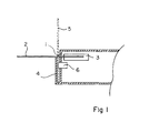
- Figure 1 shows schematically the front part of a conventional portable terminal, as marketed by the SAGEM company. Magnetic and card reading devices are both located at the front of the terminal. A slot of smart card reading 1 leads to the front of the terminal near the top of the terminal. This slot 1 is intended to receive a smart card 2 by horizontal insertion.
- a magnetic card reader slot 4 is arranged at the front face of the terminal, parallel to the latter. This slot is delimited at the front by a wall starting from the underside of the terminal and stopping at slot 1 for smart cards.
- a magnetic card 5 is shown in reading position in the slot 4.
- a magnetic head 6 is arranged at the height of the magnetic strip of the card 5 when it is in support, as shown, at the bottom of the slot 4.
- the position of the magnetic head 6, and therefore the position from the bottom of the slot 4 is determined by the size in height of the smart card reader 3.
- the distance between slot 1 and the upper face of the terminal is also determined by the overall height of the device 3.
- the only way, as shown, is to do reach the bottom of the slot 4 at the level of the lower face of the terminal. So, like the magnetic cards 5 must slide laterally through the slot 4, the boundary wall front of slot 4 is only connected to the rest of the terminal by a thin material, which makes the terminal particularly brittle.
- An object of the present invention is to provide a portable payment terminal for magnetic cards and credit cards space-saving and convenient to use.
- the present invention provides a portable payment terminal comprising a reading means magnetic card and a smart card reading means arranged at the front of the terminal to receive respective cards in reading slots with perpendicular planes, the reading slot chip card reading being open on the front face of the terminal, and the magnetic card reading slot being open on the upper side of the terminal.
- the reading slot plan of smart card is located below the card reading means magnetic.
- the bottom of the magnetic card reader slot is located at the level of the chip card reading plan.
- the terminal includes a housing consisting of a lower shell and a top shell, the smart card reading slot being located at the interface between the upper shells and lower, and the magnetic card reading slot being defined by a front face of the upper shell and a wall amount from the front part of the lower shell.
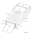
- an embodiment of the terminal of portable payment has a flat and elongated box with a keyboard 10 and a display 12 on its upper face.
- the part rear of the terminal is designed to accommodate a roll of paper for the edition of invoices, these invoices leaving by a slot 14 on the upper face of the housing.
- the terminal has a device at its front reading a smart card. As shown, a card chip 2 is inserted horizontally in the reading device by a slot 18 open on the front face of the housing.
- the card reading slot 18 chip is located near the underside of the terminal at instead of being located, as in the classic terminal of the figure 1, near the upper face.
- a reading slot 20 of magnetic card is, as in the classic terminal of the Figure 1, arranged at the front of the terminal, in parallel to this one.
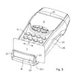
- Figure 3 shows the terminal in Figure 2 receiving a magnetic card 22 in the slot 20.
- the slot 20 is open on the side walls of the terminal and on its face superior. A user manually drives the card into a transverse movement indicated by an arrow F.
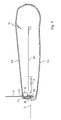
- Figure 4 shows a side sectional view of the Figure 2 terminal, a smart card 2 and a magnetic card 5 being inserted in their respective slots 18 and 20.
- a magnetic head 6 for magnetic cards 5 can be located at most near the top of the terminal.
- the reading device 3 of the smart cards is housed, as shown, between the magnetic head 6 and the bottom of the slot 20, which allows to obtain a footprint in height equal to the distance separating the bottom of the slot 20 in the upper part of the magnetic head 6.
- the slot 20 is decided at the level of the plan according to which the smart cards in the terminal through slot 18.
- the terminal box generally consists of an upper shell 24 and a lower shell 26, the slot 18 for the smart cards being located at the interface between the two hulls. So, as shown, the bottom shell 26 is continuous at the slot 20 and does not have no weakened area at this level.
- the smart card 2 is guided by its underside on the lower shell 26 towards the chip reading device 3 integral with a printed circuit 30. In its reading position, the card 2 is supported at the bottom of the device 3.
- the magnetic card 5 is supported on the guide plane of the smart card 2, this guide plane being possibly reinforced locally by a transverse element 34.
- Slot 20 for magnetic cards is defined by the front face of the upper shell 24 and the wall 22 which extends the front face of the lower shell 26 to constitute the front of the terminal.
- the wall 22, which is crossed by the smart cards 2 is provided at its ends with two uprights 22-1 (FIG. 2) which laterally define the slot 18.
- the wall 22, the front face of the upper shell 24, and the transverse element 34 may be part of the same room that is imprisoned between the two shells 24 and 26 and which supports the device magnetic reading.
- the wall 22 is slightly set back from the front of the shell lower 26, which facilitates the insertion of smart cards 2 in slot 18.
Landscapes
- Engineering & Computer Science (AREA)
- Artificial Intelligence (AREA)
- Computer Vision & Pattern Recognition (AREA)
- Physics & Mathematics (AREA)
- General Physics & Mathematics (AREA)
- Theoretical Computer Science (AREA)
- Cash Registers Or Receiving Machines (AREA)
Abstract
Description
Claims (3)
- Terminal de paiement portable comprenant un moyen (6) de lecture de carte magnétique et un moyen (3) de lecture de carte à puce disposés à l'avant du terminal pour recevoir des cartes respectives (5, 2) dans des fentes de lecture (20, 18) à plans perpendiculaires, la fente de lecture (18) de carte à puce étant ouverte sur la face avant du terminal, et la fente de lecture (20) de carte magnétique étant ouverte sur la face supérieure du terminal, caractérisé en ce que le plan de la fente de lecture (18) de carte à puce est situé en dessous du moyen de lecture de carte magnétique.
- Terminal de paiement selon la revendication 1, caractérisé en ce que le fond de la fente de lecture (20) de carte magnétique est situé au niveau du plan de la fente de lecture (18) de carte à puce.
- Terminal de paiement selon la revendication 2, caractérisé en ce qu'il comprend un boítier constitué d'une coque inférieure (26) et d'une coque supérieure (24), la fente de lecture (18) de carte à puce étant située au niveau de l'interface entre les coques supérieure et inférieure, et la fente de lecture (20) de carte magnétique étant définie par une face avant de la coque supérieure et une paroi (22) montant depuis la partie avant de la coque inférieure (26).
Applications Claiming Priority (2)
| Application Number | Priority Date | Filing Date | Title |
|---|---|---|---|
| FR9806553A FR2778996B1 (fr) | 1998-05-20 | 1998-05-20 | Terminal de paiement portable capable de traiter des cartes a puce et des cartes magnetiques |
| FR9806553 | 1998-05-20 |
Publications (2)
| Publication Number | Publication Date |
|---|---|
| EP0959424A1 true EP0959424A1 (fr) | 1999-11-24 |
| EP0959424B1 EP0959424B1 (fr) | 2009-12-09 |
Family
ID=9526674
Family Applications (1)
| Application Number | Title | Priority Date | Filing Date |
|---|---|---|---|
| EP19990410068 Expired - Lifetime EP0959424B1 (fr) | 1998-05-20 | 1999-05-19 | Terminal de paiement portable pour cartes à puce et cartes magnétiques |
Country Status (4)
| Country | Link |
|---|---|
| EP (1) | EP0959424B1 (fr) |
| DE (1) | DE69941757D1 (fr) |
| ES (1) | ES2334594T3 (fr) |
| FR (1) | FR2778996B1 (fr) |
Cited By (4)
| Publication number | Priority date | Publication date | Assignee | Title |
|---|---|---|---|---|
| US6457648B1 (en) * | 1999-10-19 | 2002-10-01 | Singular Technology Corporation | Dual-interface card reading device |
| US8025219B2 (en) | 2006-04-17 | 2011-09-27 | Hypercom Corporation | Dual purpose card reader |
| US20150317498A1 (en) * | 2012-12-12 | 2015-11-05 | Izettle Merchant Services Ab | Dual card reader for mobile device |
| US9747530B2 (en) | 2015-08-24 | 2017-08-29 | Verifone, Inc. | Payment card receiver with selectably blockable slot |
Citations (2)
| Publication number | Priority date | Publication date | Assignee | Title |
|---|---|---|---|---|
| EP0678825A1 (fr) * | 1994-04-22 | 1995-10-25 | Wynid Technologies S.A. | Dispositif d'identification et de contrôle des moyens de paiement et notamment des chèques et des cartes de paiement à circuit integré ou à piste magnétique |
| FR2733334A1 (fr) | 1995-04-20 | 1996-10-25 | Ckd Sa | Terminal de paiement polyvalent |
-
1998
- 1998-05-20 FR FR9806553A patent/FR2778996B1/fr not_active Expired - Lifetime
-
1999
- 1999-05-19 ES ES99410068T patent/ES2334594T3/es not_active Expired - Lifetime
- 1999-05-19 EP EP19990410068 patent/EP0959424B1/fr not_active Expired - Lifetime
- 1999-05-19 DE DE69941757T patent/DE69941757D1/de not_active Expired - Lifetime
Patent Citations (2)
| Publication number | Priority date | Publication date | Assignee | Title |
|---|---|---|---|---|
| EP0678825A1 (fr) * | 1994-04-22 | 1995-10-25 | Wynid Technologies S.A. | Dispositif d'identification et de contrôle des moyens de paiement et notamment des chèques et des cartes de paiement à circuit integré ou à piste magnétique |
| FR2733334A1 (fr) | 1995-04-20 | 1996-10-25 | Ckd Sa | Terminal de paiement polyvalent |
Cited By (6)
| Publication number | Priority date | Publication date | Assignee | Title |
|---|---|---|---|---|
| US6457648B1 (en) * | 1999-10-19 | 2002-10-01 | Singular Technology Corporation | Dual-interface card reading device |
| US8025219B2 (en) | 2006-04-17 | 2011-09-27 | Hypercom Corporation | Dual purpose card reader |
| US20150317498A1 (en) * | 2012-12-12 | 2015-11-05 | Izettle Merchant Services Ab | Dual card reader for mobile device |
| US9703992B2 (en) * | 2012-12-12 | 2017-07-11 | Izettle Merchant Services Ab | Dual card reader for mobile device |
| US9747530B2 (en) | 2015-08-24 | 2017-08-29 | Verifone, Inc. | Payment card receiver with selectably blockable slot |
| US10007869B2 (en) | 2015-08-24 | 2018-06-26 | Verifone, Inc. | Payment card receiver with selectably blockable slot |
Also Published As
| Publication number | Publication date |
|---|---|
| FR2778996B1 (fr) | 2000-08-11 |
| EP0959424B1 (fr) | 2009-12-09 |
| DE69941757D1 (de) | 2010-01-21 |
| FR2778996A1 (fr) | 1999-11-26 |
| ES2334594T3 (es) | 2010-03-12 |
Similar Documents
| Publication | Publication Date | Title |
|---|---|---|
| EP1609109B1 (fr) | Appareil equipe de moyens de maintien contre une surface de communication d'un support de donnees sans contact | |
| FR2667713A1 (fr) | Lecteur de carte a micro-circuit, a encombrement reduit. | |
| USD477030S1 (en) | Vending machine cashless payment terminal | |
| EP0510599B1 (fr) | Lecteur de carte à puce | |
| EP0316700A1 (fr) | Cadre de contact pour lecteur de carte à puce | |
| EP0674287A1 (fr) | Boîtier pour lecteur de carte à microcircuit | |
| EP0587488A1 (fr) | Dispositif de lecture de codes magnétiques et de codes optiques | |
| EP3016022B1 (fr) | Terminal de paiement | |
| EP0675456B1 (fr) | Boítier pour lecteur de carte à microcircuit | |
| EP0959424A1 (fr) | Terminal de paiement portable pour cartes à puce et des cartes magnétiques | |
| FR2630267A1 (fr) | Dispositif de mise en contact electrique de conducteurs repartis sur deux elements et notamment entre ceux d'une carte a memoire et ceux de son lecteur | |
| EP0643856B1 (fr) | Recepteur de carte permettant l'ejection d'une carte cassee et lecteur de carte l'utilisant | |
| FR2642868A1 (fr) | Lecteur de carte | |
| CA3036281A1 (fr) | Terminal de paiement electronique avec element monobloc de lecture de carte magnetique comprenant une lame metallique de glissement, procede de montage correspondant | |
| FR2585155A1 (fr) | Piece de vaisselle telle que soucoupe, a ssiette, plateau | |
| EP0643361B2 (fr) | Terminal électronique avec lecteur pour carte à mémoire | |
| FR2817063A1 (fr) | Carte a memoire electronique microsim | |
| FR2770102A1 (fr) | Etui protecteur pour carte de credit ou similaire | |
| FR3081795B1 (fr) | Dispositif de rangement porte-carte et console comprenant un tel dispositif | |
| CA2275949A1 (fr) | Gabarit pour le controle geometrique de cartes a memoire | |
| FR2795194A1 (fr) | Extension pour module electronique de type pcmcia | |
| EP1131770A1 (fr) | Dispositif de lecture de carte a microcircuit | |
| FR2626094A1 (fr) | Dispositif de traitement de cartes | |
| EP1902427A1 (fr) | Machine de distribution de produits et/ou de services munie d'un lecteur de billets | |
| EP0549403A1 (fr) | Procédé et dispositif pour rendre imperdable une vis de fixation d'un circuit imprimé sur un support |
Legal Events
| Date | Code | Title | Description |
|---|---|---|---|
| PUAI | Public reference made under article 153(3) epc to a published international application that has entered the european phase |
Free format text: ORIGINAL CODE: 0009012 |
|
| AK | Designated contracting states |
Kind code of ref document: A1 Designated state(s): BE DE ES FR GB IE IT |
|
| AX | Request for extension of the european patent |
Free format text: AL;LT;LV;MK;RO;SI |
|
| 17P | Request for examination filed |
Effective date: 20000512 |
|
| AKX | Designation fees paid |
Free format text: BE DE ES FR GB IE IT |
|
| 17Q | First examination report despatched |
Effective date: 20070403 |
|
| RAP1 | Party data changed (applicant data changed or rights of an application transferred) |
Owner name: SAGEM MONETEL |
|
| RAP1 | Party data changed (applicant data changed or rights of an application transferred) |
Owner name: INGENICO FRANCE |
|
| GRAP | Despatch of communication of intention to grant a patent |
Free format text: ORIGINAL CODE: EPIDOSNIGR1 |
|
| RIN1 | Information on inventor provided before grant (corrected) |
Inventor name: DEMANGE, FABIEN |
|
| GRAS | Grant fee paid |
Free format text: ORIGINAL CODE: EPIDOSNIGR3 |
|
| GRAA | (expected) grant |
Free format text: ORIGINAL CODE: 0009210 |
|
| AK | Designated contracting states |
Kind code of ref document: B1 Designated state(s): BE DE ES FR GB IE IT |
|
| REG | Reference to a national code |
Ref country code: GB Ref legal event code: FG4D Free format text: NOT ENGLISH |
|
| REG | Reference to a national code |
Ref country code: IE Ref legal event code: FG4D |
|
| REF | Corresponds to: |
Ref document number: 69941757 Country of ref document: DE Date of ref document: 20100121 Kind code of ref document: P |
|
| REG | Reference to a national code |
Ref country code: ES Ref legal event code: FG2A Ref document number: 2334594 Country of ref document: ES Kind code of ref document: T3 |
|
| REG | Reference to a national code |
Ref country code: IE Ref legal event code: FD4D |
|
| PG25 | Lapsed in a contracting state [announced via postgrant information from national office to epo] |
Ref country code: IE Free format text: LAPSE BECAUSE OF FAILURE TO SUBMIT A TRANSLATION OF THE DESCRIPTION OR TO PAY THE FEE WITHIN THE PRESCRIBED TIME-LIMIT Effective date: 20091209 |
|
| PLBE | No opposition filed within time limit |
Free format text: ORIGINAL CODE: 0009261 |
|
| STAA | Information on the status of an ep patent application or granted ep patent |
Free format text: STATUS: NO OPPOSITION FILED WITHIN TIME LIMIT |
|
| 26N | No opposition filed |
Effective date: 20100910 |
|
| BERE | Be: lapsed |
Owner name: INGENICO FRANCE Effective date: 20100531 |
|
| PG25 | Lapsed in a contracting state [announced via postgrant information from national office to epo] |
Ref country code: BE Free format text: LAPSE BECAUSE OF NON-PAYMENT OF DUE FEES Effective date: 20100531 |
|
| REG | Reference to a national code |
Ref country code: FR Ref legal event code: PLFP Year of fee payment: 17 |
|
| REG | Reference to a national code |
Ref country code: FR Ref legal event code: TP Owner name: COMPAGNIE INDUSTRIELLE ET FINANCIERE D'INGENIE, FR Effective date: 20160111 |
|
| REG | Reference to a national code |
Ref country code: FR Ref legal event code: CD Owner name: INGENICO GROUP, FR Effective date: 20160304 Ref country code: FR Ref legal event code: CA Effective date: 20160304 |
|
| REG | Reference to a national code |
Ref country code: FR Ref legal event code: PLFP Year of fee payment: 18 |
|
| REG | Reference to a national code |
Ref country code: FR Ref legal event code: PLFP Year of fee payment: 19 |
|
| REG | Reference to a national code |
Ref country code: FR Ref legal event code: PLFP Year of fee payment: 20 |
|
| PGFP | Annual fee paid to national office [announced via postgrant information from national office to epo] |
Ref country code: DE Payment date: 20180514 Year of fee payment: 20 Ref country code: ES Payment date: 20180625 Year of fee payment: 20 |
|
| PGFP | Annual fee paid to national office [announced via postgrant information from national office to epo] |
Ref country code: IT Payment date: 20180514 Year of fee payment: 20 Ref country code: FR Payment date: 20180524 Year of fee payment: 20 |
|
| PGFP | Annual fee paid to national office [announced via postgrant information from national office to epo] |
Ref country code: GB Payment date: 20180518 Year of fee payment: 20 |
|
| REG | Reference to a national code |
Ref country code: DE Ref legal event code: R071 Ref document number: 69941757 Country of ref document: DE |
|
| REG | Reference to a national code |
Ref country code: GB Ref legal event code: PE20 Expiry date: 20190518 |
|
| PG25 | Lapsed in a contracting state [announced via postgrant information from national office to epo] |
Ref country code: GB Free format text: LAPSE BECAUSE OF EXPIRATION OF PROTECTION Effective date: 20190518 |
|
| REG | Reference to a national code |
Ref country code: ES Ref legal event code: FD2A Effective date: 20200903 |
|
| PG25 | Lapsed in a contracting state [announced via postgrant information from national office to epo] |
Ref country code: ES Free format text: LAPSE BECAUSE OF EXPIRATION OF PROTECTION Effective date: 20190520 |