EP0959478A1 - Herstellungsverfahren für ein dünne magnetscheibe mit mikrokristalline struktur - Google Patents
Herstellungsverfahren für ein dünne magnetscheibe mit mikrokristalline struktur Download PDFInfo
- Publication number
- EP0959478A1 EP0959478A1 EP98901011A EP98901011A EP0959478A1 EP 0959478 A1 EP0959478 A1 EP 0959478A1 EP 98901011 A EP98901011 A EP 98901011A EP 98901011 A EP98901011 A EP 98901011A EP 0959478 A1 EP0959478 A1 EP 0959478A1
- Authority
- EP
- European Patent Office
- Prior art keywords
- roller
- magnets
- crystalline structure
- thin
- fine crystalline
- Prior art date
- Legal status (The legal status is an assumption and is not a legal conclusion. Google has not performed a legal analysis and makes no representation as to the accuracy of the status listed.)
- Granted
Links
Images

Classifications
-
- H—ELECTRICITY
- H01—ELECTRIC ELEMENTS
- H01F—MAGNETS; INDUCTANCES; TRANSFORMERS; SELECTION OF MATERIALS FOR THEIR MAGNETIC PROPERTIES
- H01F1/00—Magnets or magnetic bodies characterised by the magnetic materials therefor; Selection of materials for their magnetic properties
- H01F1/01—Magnets or magnetic bodies characterised by the magnetic materials therefor; Selection of materials for their magnetic properties of inorganic materials
- H01F1/03—Magnets or magnetic bodies characterised by the magnetic materials therefor; Selection of materials for their magnetic properties of inorganic materials characterised by their coercivity
- H01F1/032—Magnets or magnetic bodies characterised by the magnetic materials therefor; Selection of materials for their magnetic properties of inorganic materials characterised by their coercivity of hard-magnetic materials
- H01F1/04—Magnets or magnetic bodies characterised by the magnetic materials therefor; Selection of materials for their magnetic properties of inorganic materials characterised by their coercivity of hard-magnetic materials metals or alloys
- H01F1/047—Alloys characterised by their composition
- H01F1/053—Alloys characterised by their composition containing rare earth metals
- H01F1/055—Alloys characterised by their composition containing rare earth metals and magnetic transition metals, e.g. SmCo5
- H01F1/057—Alloys characterised by their composition containing rare earth metals and magnetic transition metals, e.g. SmCo5 and IIIa elements, e.g. Nd2Fe14B
-
- C—CHEMISTRY; METALLURGY
- C22—METALLURGY; FERROUS OR NON-FERROUS ALLOYS; TREATMENT OF ALLOYS OR NON-FERROUS METALS
- C22C—ALLOYS
- C22C38/00—Ferrous alloys, e.g. steel alloys
- C22C38/002—Ferrous alloys, e.g. steel alloys containing In, Mg, or other elements not provided for in one single group C22C38/001 - C22C38/60
-
- B—PERFORMING OPERATIONS; TRANSPORTING
- B82—NANOTECHNOLOGY
- B82Y—SPECIFIC USES OR APPLICATIONS OF NANOSTRUCTURES; MEASUREMENT OR ANALYSIS OF NANOSTRUCTURES; MANUFACTURE OR TREATMENT OF NANOSTRUCTURES
- B82Y25/00—Nanomagnetism, e.g. magnetoimpedance, anisotropic magnetoresistance, giant magnetoresistance or tunneling magnetoresistance
-
- H—ELECTRICITY
- H01—ELECTRIC ELEMENTS
- H01F—MAGNETS; INDUCTANCES; TRANSFORMERS; SELECTION OF MATERIALS FOR THEIR MAGNETIC PROPERTIES
- H01F1/00—Magnets or magnetic bodies characterised by the magnetic materials therefor; Selection of materials for their magnetic properties
- H01F1/01—Magnets or magnetic bodies characterised by the magnetic materials therefor; Selection of materials for their magnetic properties of inorganic materials
- H01F1/03—Magnets or magnetic bodies characterised by the magnetic materials therefor; Selection of materials for their magnetic properties of inorganic materials characterised by their coercivity
- H01F1/032—Magnets or magnetic bodies characterised by the magnetic materials therefor; Selection of materials for their magnetic properties of inorganic materials characterised by their coercivity of hard-magnetic materials
- H01F1/04—Magnets or magnetic bodies characterised by the magnetic materials therefor; Selection of materials for their magnetic properties of inorganic materials characterised by their coercivity of hard-magnetic materials metals or alloys
- H01F1/047—Alloys characterised by their composition
- H01F1/053—Alloys characterised by their composition containing rare earth metals
- H01F1/055—Alloys characterised by their composition containing rare earth metals and magnetic transition metals, e.g. SmCo5
- H01F1/057—Alloys characterised by their composition containing rare earth metals and magnetic transition metals, e.g. SmCo5 and IIIa elements, e.g. Nd2Fe14B
- H01F1/0579—Alloys characterised by their composition containing rare earth metals and magnetic transition metals, e.g. SmCo5 and IIIa elements, e.g. Nd2Fe14B with exchange spin coupling between hard and soft nanophases, e.g. nanocomposite spring magnets
-
- H—ELECTRICITY
- H01—ELECTRIC ELEMENTS
- H01F—MAGNETS; INDUCTANCES; TRANSFORMERS; SELECTION OF MATERIALS FOR THEIR MAGNETIC PROPERTIES
- H01F1/00—Magnets or magnetic bodies characterised by the magnetic materials therefor; Selection of materials for their magnetic properties
- H01F1/01—Magnets or magnetic bodies characterised by the magnetic materials therefor; Selection of materials for their magnetic properties of inorganic materials
- H01F1/03—Magnets or magnetic bodies characterised by the magnetic materials therefor; Selection of materials for their magnetic properties of inorganic materials characterised by their coercivity
- H01F1/032—Magnets or magnetic bodies characterised by the magnetic materials therefor; Selection of materials for their magnetic properties of inorganic materials characterised by their coercivity of hard-magnetic materials
- H01F1/04—Magnets or magnetic bodies characterised by the magnetic materials therefor; Selection of materials for their magnetic properties of inorganic materials characterised by their coercivity of hard-magnetic materials metals or alloys
- H01F1/047—Alloys characterised by their composition
- H01F1/053—Alloys characterised by their composition containing rare earth metals
- H01F1/055—Alloys characterised by their composition containing rare earth metals and magnetic transition metals, e.g. SmCo5
- H01F1/058—Alloys characterised by their composition containing rare earth metals and magnetic transition metals, e.g. SmCo5 and IVa elements, e.g. Gd2Fe14C
Definitions
- This invention relates to a manufacturing method for thin-plate magnets ideal for magnetic circuits used in various small motors, actuators, and magnetic sensors, etc.
- magnets are obtained, by the method of continuously casting a melt having a specific composition containing 6 at% or less of a rare earth element and 15 to 30 at% boron, on a turning cooling roller or rollers, in a prescribed reduced-pressure inactive gas atmosphere, so that the magnets have a crystalline structure wherein, in the state wherein they are cast, 90% or more is actually constituted by an Fe 3 B compound and ⁇ -Fe coexisting with a compound phase having an Nd 2 Fe 14 B crystalline structure, and exhibit a fine crystalline structure having for each configuring phase a mean crystal grain diameter of from 10 to 50 nm.
- the present invention relates to a method of manufacturing thin-plate magnets, immediately from the alloy melt, having a fine crystalline structure with a thickness of 70 to 500 ⁇ m and exhibiting magnetic properties of iHc ⁇ 2.5 kOe and Br ⁇ 9 kG.
- thin-plate permanent magnets wherein the thickness of the permanent magnet itself is on the order of 100 to 500 ⁇ m are being sought.
- the great difficulty of obtaining bulk material for Nd-Fe-B sintered magnets having a thickness of less than 500 ⁇ m can only be fabricated by grinding a plate-form sintered body several mm in thickness or by the method of slicing the bulk material with a wire saw, leading to the problems of high cost and low yield.
- Nd-Fe-B boded magnets are obtained by using a resin to bond together powder having a diameter several 10 to 500 ⁇ m and a thickness of approximately 30 ⁇ m, wherefore it is very difficult to form bonded magnets having a thin-plate thickness of 100 to 300 ⁇ m.
- Koon proposed a method for manufacturing a permanent magnet made up of fine crystals wherein an La-R-B-Fe amorphous alloy containing La as a mandatory element is subjected to a crystallizing heat treatment.
- the permanent magnet materials noted above exhibit a Br of around 10 kG and an iHc of 2 to 3 kOe, wherein expensive Nd is contained in a low concentration of 4 at% or so, wherefore the raw materials mixed in are less expensive than for Nd-Fe-B magnets wherein the main phase is Nd 2 Fe 14 B.
- U.S. Patent 508,266 is disclosed a rapidly solidified Nd-Fe-B magnet material consisting of a structure formed of a crystalline substance exhibiting hard magnetism that is directly obtained by rapidly solidifying an alloy melt on a roller rotating with a circumferential speed of about 20 m/s.
- the rapidly solidified alloy flakes obtained under these conditions have a thickness of around 30 ⁇ m, wherefore, although they can be ground to a powder having a grain diameter of between 10 and 500 ⁇ m or so and thus used in the bonded magnets described earlier, they cannot be used in thin-plate magnets.
- An object of the present invention is to resolve the problems noted above in Nd-Fe-B magnets containing 6 at% or less of a rare earth element and exhibiting fine crystallization. Another object thereof is to obtain, by casting, magnets exhibiting a performance-to-cost ratio comparable to hard ferrite magnets and exhibiting an intrinsic coercive force iHc of 2.5 kOe or greater and a residual magnetic flux density Br of 9 kG or greater. Yet another object thereof is to provide a method for manufacturing thin-plate magnets having a fine crystalline structure and thickness of 70 to 500 ⁇ m wherewith it is possible to make magnetic circuits smaller and thinner.
- the iHc of the magnets can be improved to 2.5 kOe or better, the optimum roller circumferential speed range wherewith hard magnetic properties are obtained can be expanded, in comparison to manufacturing conditions conventional Nd-Fe-B ternary magnet, and, at the same time, fine crystalline permanent magnets can be obtained having a thickness of 70 to 500 ⁇ m.
- the present invention perfected.
- an alloy melt is used that is expressed by a composition formula of either Fe 100-x-y-z R x A y M z or (Fe 1-m Co m ) 100-x-y-z R x A y M z (where R is one or more elements in the group Pr, Nd, Tb, and Dy, A is either C, or B, or C and B, and M is one or more elements in the group Al, Si, Ti, V, Cr, Mn, Ni, Cu, Ga, Zr, Nb, Ag, Hf, Ta, W, Pt, Au, and Pb), and that satisfies the conditions 1 ⁇ x ⁇ 6 at%, 15 ⁇ y ⁇ 30 at%, 0.01 ⁇ z ⁇ 7 at%, and 0.001 ⁇ m ⁇ 0.5 for the symbols x, y, z, and m delimiting the composition range, respectively.
- this alloy melt is is continuously cast on a cooling roller or rollers that rotate with a roller circumferential speed of 1 to 10 m/s (at an average cooling speed of from 3 ⁇ 10 3 to 1 ⁇ 10 5 °C/sec), in a reduced-pressure inert or inactive gas atmosphere at 30 kPa or less.
- the present invention is a manufacturing method wherewith can be obtained thin-plate permanent magnets exhibiting magnetic properties of iHc ⁇ 2.5 kOe and Br ⁇ 9 kG, wherein the alloy melt noted above is continuously cast on a rotating cooling roller or rollers to yield a cast alloy having a thickness of 70 to 500 ⁇ m, made up of fine crystallites having a mean crystalline grain diameter of 10 nm or less, whereafter this is subjected to a heat treatment to grow crystal grains in a temperature region of 550°C to 750°C, thereby yielding a fine crystalline alloy exhibiting a mean crystalline grain diameter of 10 to 50 nm.
- R is less than 1 at%, an iHc of 2.5 kOe or greater cannot be obtained, and when it reaches 6 at% or greater, a Br of 9 kG or higher cannot be obtained, wherefore the range is set at 1 at% or more but less than 6 at%.
- the preferred range is from 2 at%to 5.5 at%.
- the A in the composition formula is either carbon or boron or both carbon and boron.
- total A is below 15 at%, the presence of ⁇ -Fe in the metal structure after liquid cooling becomes pronounced, and the fabrication of the compound containing the Nd 2 Fe 14 B crystalline structure necessary to the manifestation of coercive force is impaired, so that only an iHc below 1 kOe can be obtained.
- that total exceeds 30 at%, on the other hand, the squareness of the demagnetization curve declines sharply. Therefore the range is set at above 15 at% but no greater than 30 at%. The preferred range is from 16 at% to 20 at%.
- the Al, Si, Ti, V, Cr, Mn, Ni, Cu, Ga, Zr, Nb, Mo, Ag, Hf, Ta, W, Pt, Au, and Pb for the added element M contribute in imparting a finer structure to the fine crystalline permanent magnet, improve the coercive force, improve the squareness of the demagnetization curve, and increase both Br and (BH)max.
- the added element M also, as does the Co, expands the ideal roller circumferential speed range wherewith the magnetic properties can be obtained when rapidly solidifying the alloy melt on the rotating roller to fabricate the fine crystalline permanent magnets, and enables the rapidly solidification conditions for obtaining the magnetic properties noted earlier to be relaxed
- These effects are not realized when the added element M is less than 0.01 at%, while at levels above 7 at%, the magnetic property of Br ⁇ 9 kG cannot be realized.
- the range is set at 0.01 at% to 7 at%.
- the preferred range is 0.05 at% to 5 at%.
- the cooling be done so that thin-plate magnets are obtained having in each configuring phase a mean crystalline grain diameter of 10 nm to 50 nm which is necessary to elicit the magnetic properties of iHc ⁇ 2.5 kOe and Br ⁇ 9 kG, formed of a crystalline micro structure wherein an Fe 3 B compound and ⁇ -Fe actually coexist 90% or more with a compound phase having an Nd 2 Fe 14 B crystalline structure, in the condition in which cast.
- a feature of the present invention is the specific pressure of the atmosphere when continuously casting the alloy melt.
- the reason for the limitation thereon is that, when the casting atmosphere exceeds 30 kPa, gas enters in between the cooling rollers and the alloy melt, whereupon the uniformity of the rapid solidification conditions for the cast alloy is lost. As a consequence, a coarse ⁇ -Fe containing metal structure is formed, and the magnetic properties of iHc ⁇ 2.5 kOe and Br ⁇ 9 kG cannot be realized.
- the rapid solidification atmosphere is thus made 30 kPa or lower, and preferably 10kPa or lower.
- the atmosphere gas should be an inert or inactive gas atmosphere to prevent oxidation of the alloy melt.
- An Ar atmosphere is the preferred atmosphere.
- a heat treatment may be performed to achieve grain growth.
- the heat-treatment temperature at which the magnetic properties are maximized depends on the composition, but at heat-treatment temperatures below 500°C crystallization is not induced and, hence, a mean crystalline grain diameter of 10 nm or higher is not obtained.
- the heat-treatment temperature exceeds 750°C, on the other hand, grain coarsening is pronounced, iHc, Br, and the squareness of the demagnetization curve deteriorate, and the magnetic properties noted above are not obtained.
- the heat-treatment temperature is limited to the range of 500 - 750°C.
- the heat treatment be conducted either in an inert or inactive gas atmosphere of Ar gas or N 2 gas, or in a vacuum at 1.33 Pa or less, to prevent oxidation.
- the magnetic properties are not dependent on the heat-treatment time, when that time exceeds 6 hours, Br does tend to decline with the passage of time,wherefore a time of less than 6 hours is to be preferred.
- a continuous casting method can be adopted which employs either a single cooling roller or double rollers.
- the thickness of the cast alloy exceeds 500 ⁇ m, however, several hundred nm coarse ⁇ -Fe and Fe 2 B are formed, wherefore the magnetic properties of iHc ⁇ 2.5 kOe and Br ⁇ 9 kG cannot be realized.
- the thickness of the cast alloy is 70 ⁇ m or lower, on the other hand, the volume fraction of crystalline microstructure contained in the cast alloy declines, and the amorphous phase increases, making it necessary to crystallize the amorphous [alloy] by heat treatment.
- the rise in alloy temperature brought about by the heat release associated with this amorphous crystallization induces grain growth in the crystalline structure already separated immediately after rapid solidification, resulting in a metal structure that is rougher than the metal structure where in the mean crystalline grain diameter is 10 to 50 nm as needed to obtain the magnetic properties of iHc ⁇ 2.5 kOe and Br ⁇ 9 kG, and a Br of 10 kG or higher cannot be obtained.
- the rapid-cooling casting conditions are limited so as to produce cast alloy having a thickness of 70 to 500 ⁇ m.
- cooling rollers used in the continuous casting process, in terms of thermal conductivity, an aluminum alloy, copper alloy, iron, carbon steel, brass, or tungsten can be used. It is also possible to use cooling rollers having a plating on the surface of a roller made of a material noted above, where the plating is either the same or a different material. Either a copper alloy or carbon steel is preferable for the cooling roller material in the interest of mechanical strength and cost.
- the roller circumference speed is 1.5 m/s or lower, on the other hand, the cast alloy thickness exceeds 500 ⁇ m, wherefore ⁇ -Fe and Fe 2 B are formed having a coarseness of several hundreds of nm, and the magnetic properties of iHc ⁇ 2.5 kOe and Br ⁇ 9 kG are not realized, so this is undesirable. That being so, the circumference speed of the copper rollers is limited to a range of 1.5 m/s to 10 m/s. The preferred range is 1 m/s to 6 m/s.
- the alloy melt wettability of the iron cooling roller is superior to that of the copper roller, wherefore when the roller circumferential speed exceeds 7 m/s, the cast alloy thickness drops below 70 ⁇ m, the crystalline microstructure contained in the cast alloy declines, and the amorphous phase increases.
- the roller circumference speed is below 1 m/s (average cooling speed 3 ⁇ 10 3 °C/sec)
- the cast alloy thickness exceeds 500 ⁇ m, wherefore ⁇ -Fe and Fe 2 B having a coarseness of several hundreds of nm are separated and the magnetic properties of iHc ⁇ 2.5 kOe and Br ⁇ 9 kG are not realized.
- the roller circumferential speed is limited to a range of 1 m/s to 7 m/s, and preferably to a range of 1.5 m/s to 5.5 m/s.
- the alloy thickness is determined by the distance between the rollers.
- the distance between the two rollers is greater than 0.5 mm, the melt passing between the rollers does not make contact with the one of the cooling rollers and so is not effectively cooled, resulting in a metal microstructure containing coarse ⁇ -Fe, so this is undesirable.
- the distance between the rollers is below 0.005 mm, on the other hand, the melt overflows from between the rollers, so that casting cannot be continued in an uninterrupted fashion, wherefore this is also undesirable. Accordingly, the distance between the two rollers is limited to a range of 0.005 mm to 0.5 mm, and preferably to 0.05 to 0.2 mm.
- the roller circumference speed is limited to a range of 1 to 8 m/s.
- the preferred range is 1.5 to 5 m/s.
- the crystalline phase of the fine crystalline permanent magnets according to the present invention is characterized by the fact that an Fe 3 B compound exhibiting soft magnetism and ⁇ -Fe coexist with a hard-magnetic compound phase having an Nd 2 Fe 14 B crystalline structure in the same structure, and by the fact that it is made up of fine crystalline aggregates wherein the mean crystalline grain diameter in each configuring phase is within the range of 15 to 50 nm.
- the mean crystalline grain diameter configuring the fine crystalline permanent magnet exceeds 50 nm, Br and the squareness of the demagnetization curve deteriorate, and the magnetic property of Br ⁇ 9 kG cannot be obtained.
- the finer the mean crystalline grain size the better, but at sizes below 15 nm, a decline in iHc is induced, wherefore the lower limit is made 15 nm.
- the thin-plate magnets obtained with the present invention exhibit a thickness of 70 to 500 ⁇ m, and, in terms of surface smoothness, exhibit centerline roughness Ra ⁇ 5 ⁇ m, maximum height ⁇ 20 ⁇ m, and 10-point average roughness Rz ⁇ 10 ⁇ m
- the molten surface was pressurized with Ar gas and, at room temperature, the melt was continuously cast from a height of 0.7 mm at the outer circumferential surface of a Cu cooling roller turning at the roller circumferential speed indicated in Table 1-2.
- the melt was continuously cast from a height of 0.7 mm at the outer circumferential surface of a Cu cooling roller turning at the roller circumferential speed indicated in Table 1-2.
- the thin-plate magnets obtained have a metal structure wherein an Fe 3 B compound and ⁇ -Fe coexist with a compound phase having an Nd 2 Fe 14 B crystalline structure.
- a fine crystalline structure is exhibited having a mean crystalline grain diameter of 15 nm to 50 nm.
- the magnetic properties of the thin-plate magnets obtained were measured with a VSM after taking the thin-plate magnets of prescribed shape stamped out in round disk shapes 5 mm in diameter using an ultrasonic stamping machine and magnetizing them in a 60-kOe pulsed magnetic field.
- the magnetic properties and mean crystalline grain diameters are listed in Table 2.
- the elements Co, Al, Si, Ti, V, Cr, Mn, Ni, Cu, Ga, Zr, Nb, Hf, Ta, W, Mo, Ag, Pt, Au, and Pb partially replace the Fe in the configuring phases.
- the mean crystalline grain diameter was less than 10 nm, wherefore the rapid solidified alloys were heat-treated by maintaining them at 670°C for 10 minutes in Ar gas to make the mean crystalline grain diameter 10 nm or greater.
- the magnetic properties were determined as in the first embodiment by measurements made using a VSM on the thin-plate magnets fabricated into prescribed shapes. The measurement results are given in Table 2.
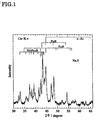
- test sample No. 20 exhibited a metal structure comprising hard-magnetic Nd 2 Fe 14 B and soft-magnetic Fe 3 B and ⁇ -Fe.
- Nd 2 Fe 14 B could be slightly verified, but almost no Fe 3 B could be verified.
- Test sample No. 22 exhibited a metal structure having ⁇ -Fe as the main phase
- test sample No. 23 exhibited a structure comprising the non-magnetic phase Nd 2 Fe 23 B 3 and ⁇ -Fe, with the metal structure in both of these cases containing no hard-magnetic Nd 2 Fe 14 B.
- the magnetic properties measured by VSM in test samples No. 20 - 23 are listed in Table 2.
- roller circumferential speed ranges wherein coercive force is manifest in these Nd-Fe-B ternary test samples are narrow as compared to Embodiment Examples No. 5 and No. 9 containing Co and Cr, Nb, Cu, and Ga.
- Table 3 is indicated the roller circumferential speed range wherein an iHc of 2.5 kOe or greater is obtained when rapid solidification the melt having the alloy composition of Comparison No. 20.
- the present invention is an improved manufacturing method for low-rare-earth-concentration Nd-Fe-B fine crystalline permanent magnets containing both soft magnetic phases and hard magnetic phases.
- fine crystalline permanent magnets having a 15-nm to 50-nm fine crystalline structure are fabricated immediately from alloy melts by continuous casting on a rotating cooling roller in a specific reduced-pressure inert or inactive gas atmosphere, by adding Co, Al, Si, Ti, V, Cr, Mn, Ni, Cu, Ga, Zr, Nb, Mo, Ag, Hf, Ta, W, Pt, Au, or Pb into the alloy melt, the coercive force of the magnet can be improved, and the magnetic properties of iHc ⁇ 2.5 kOe and Br ⁇ 9 kG can be realized.
- the present invention inexpensively provides thin-plate magnets of a thickness of 70 to 500 ⁇ m that exhibit performance-to-cost ratios comparable to hard-ferrite magnets, which could not previously be produced in large quantities at low cost, and thereby contributes to making magnetic circuits smaller and thinner.
Landscapes
- Chemical & Material Sciences (AREA)
- Engineering & Computer Science (AREA)
- Crystallography & Structural Chemistry (AREA)
- Inorganic Chemistry (AREA)
- Power Engineering (AREA)
- Nanotechnology (AREA)
- Mechanical Engineering (AREA)
- Organic Chemistry (AREA)
- Metallurgy (AREA)
- Composite Materials (AREA)
- Materials Engineering (AREA)
- Hard Magnetic Materials (AREA)
- Continuous Casting (AREA)
- Manufacturing Cores, Coils, And Magnets (AREA)
Applications Claiming Priority (5)
| Application Number | Priority Date | Filing Date | Title |
|---|---|---|---|
| JP3988097 | 1997-02-06 | ||
| JP3988097 | 1997-02-06 | ||
| JP7444397 | 1997-03-10 | ||
| JP7444397 | 1997-03-10 | ||
| PCT/JP1998/000330 WO1998035364A1 (en) | 1997-02-06 | 1998-01-28 | Method of manufacturing thin plate magnet having microcrystalline structure |
Publications (3)
| Publication Number | Publication Date |
|---|---|
| EP0959478A1 true EP0959478A1 (de) | 1999-11-24 |
| EP0959478A4 EP0959478A4 (de) | 2000-08-09 |
| EP0959478B1 EP0959478B1 (de) | 2004-03-31 |
Family
ID=26379287
Family Applications (1)
| Application Number | Title | Priority Date | Filing Date |
|---|---|---|---|
| EP98901011A Expired - Lifetime EP0959478B1 (de) | 1997-02-06 | 1998-01-28 | Herstellungsverfahren für ein dünne magnetscheibe mit mikrokristalline struktur |
Country Status (6)
| Country | Link |
|---|---|
| US (1) | US6386269B1 (de) |
| EP (1) | EP0959478B1 (de) |
| KR (1) | KR100345995B1 (de) |
| CN (1) | CN1111879C (de) |
| DE (1) | DE69822798T2 (de) |
| WO (1) | WO1998035364A1 (de) |
Cited By (12)
| Publication number | Priority date | Publication date | Assignee | Title |
|---|---|---|---|---|
| EP1076907A1 (de) * | 1999-03-05 | 2001-02-21 | Pioneer Metals and Technology, Inc. | Magnet material |
| EP0983831A3 (de) * | 1998-09-01 | 2002-09-04 | Sumitomo Special Metals Company Limited | Verfahren zum Schneiden von Seltenerdlegierungen, Verfahren zum Herstellen von Platten aus Seltenerdlegierungen und Verfahren zum Herstellen von Seltenerdlegierungsmagneten mittels Drahtsägen, und Schwingspulenmotor |
| US6478889B2 (en) | 1999-12-21 | 2002-11-12 | Sumitomo Special Metals Co., Ltd. | Iron-base alloy permanent magnet powder and method for producing the same |
| US6585831B2 (en) | 1999-12-27 | 2003-07-01 | Sumitomo Special Metals Co., Ltd. | Method of making iron base magnetic material alloy powder |
| EP1447823A4 (de) * | 2001-11-20 | 2005-03-02 | Neomax Co Ltd | Zusammensetzung für einen auf seltenerdelementen basierenden, gebondeten magneten und gebondeter magnet damit |
| EP1446816A4 (de) * | 2001-11-22 | 2005-03-02 | Neomax Co Ltd | Nanozusammensetzungsmagnet |
| US7195661B2 (en) | 1999-03-05 | 2007-03-27 | Pioneer Metals And Technology, Inc. | Magnetic material |
| US7208097B2 (en) | 2001-05-15 | 2007-04-24 | Neomax Co., Ltd. | Iron-based rare earth alloy nanocomposite magnet and method for producing the same |
| US7217328B2 (en) | 2000-11-13 | 2007-05-15 | Neomax Co., Ltd. | Compound for rare-earth bonded magnet and bonded magnet using the compound |
| US7297213B2 (en) | 2000-05-24 | 2007-11-20 | Neomax Co., Ltd. | Permanent magnet including multiple ferromagnetic phases and method for producing the magnet |
| US7507302B2 (en) | 2001-07-31 | 2009-03-24 | Hitachi Metals, Ltd. | Method for producing nanocomposite magnet using atomizing method |
| CN1959878B (zh) * | 2005-11-02 | 2010-09-15 | 四川大学 | 一种纳米晶钕铁硼永磁块体的制备方法 |
Families Citing this family (9)
| Publication number | Priority date | Publication date | Assignee | Title |
|---|---|---|---|---|
| JP3654236B2 (ja) * | 2001-11-07 | 2005-06-02 | 株式会社日立製作所 | 電極デバイスの製造方法 |
| CN101509107B (zh) * | 2009-02-23 | 2010-06-02 | 浙江大学 | 铁基非晶合金磁性材料及其制备方法 |
| CN103331449B (zh) * | 2013-06-05 | 2015-09-02 | 华南理工大学 | 一种超高塑性双尺度分布的超细晶/微米晶块体铁材料及其制备方法 |
| DE102016104384A1 (de) * | 2015-03-13 | 2016-09-15 | Showa Denko K.K. | Gesinterter Magnet auf R-T-B-Seltenerdbasis und Legierung für einen gesinterten Magneten auf R-T-B-Seltenerdbasis |
| JP6672753B2 (ja) * | 2015-03-13 | 2020-03-25 | Tdk株式会社 | R−t−b系希土類焼結磁石及びr−t−b系希土類焼結磁石用合金 |
| CN108085608A (zh) * | 2016-11-23 | 2018-05-29 | 龙岩紫荆创新研究院 | 一种R-B-Ti-Fe合金粉末及其制备方法与该合金粉末制备的热压磁体 |
| CN110491615A (zh) * | 2019-07-18 | 2019-11-22 | 山东科技大学 | 一种用于小型直流电机的钕铁硼磁体制备方法 |
| CN112216499A (zh) * | 2020-08-25 | 2021-01-12 | 宁波同创强磁材料有限公司 | 一种抗氧化烧结钕铁硼磁体的制备方法 |
| CN118762922B (zh) * | 2024-09-05 | 2025-01-10 | 宁波迈泰克磁材科技有限公司 | 一种基体磁钢的晶界及晶粒结构控制方法 |
Family Cites Families (26)
| Publication number | Priority date | Publication date | Assignee | Title |
|---|---|---|---|---|
| US4402770A (en) | 1981-10-23 | 1983-09-06 | The United States Of America As Represented By The Secretary Of The Navy | Hard magnetic alloys of a transition metal and lanthanide |
| US4792368A (en) * | 1982-08-21 | 1988-12-20 | Sumitomo Special Metals Co., Ltd. | Magnetic materials and permanent magnets |
| DE3379131D1 (en) | 1982-09-03 | 1989-03-09 | Gen Motors Corp | Re-tm-b alloys, method for their production and permanent magnets containing such alloys |
| US4840684A (en) * | 1983-05-06 | 1989-06-20 | Sumitomo Special Metals Co, Ltd. | Isotropic permanent magnets and process for producing same |
| JPS6032306A (ja) * | 1983-08-02 | 1985-02-19 | Sumitomo Special Metals Co Ltd | 永久磁石 |
| JPS60152008A (ja) * | 1984-01-20 | 1985-08-10 | Tdk Corp | 永久磁石用材料 |
| JPS6115943A (ja) * | 1984-07-03 | 1986-01-24 | Kawasaki Steel Corp | 希土類系永久磁石薄帯 |
| US4767450A (en) * | 1984-11-27 | 1988-08-30 | Sumitomo Special Metals Co., Ltd. | Process for producing the rare earth alloy powders |
| US4762574A (en) * | 1985-06-14 | 1988-08-09 | Union Oil Company Of California | Rare earth-iron-boron premanent magnets |
| EP0248981B1 (de) | 1986-06-12 | 1993-07-07 | Kabushiki Kaisha Toshiba | Dauermagnet und Dauermagnetlegierung |
| JPS6318602A (ja) * | 1986-07-11 | 1988-01-26 | Toshiba Corp | 希土類鉄系永久磁石の製造方法 |
| DE3777523D1 (de) | 1986-10-10 | 1992-04-23 | Philips Nv | Magnetisches material aus eisen, bor und seltenerdmetall. |
| US4881986A (en) * | 1986-11-26 | 1989-11-21 | Tokin Corporation | Method for producing a rare earth metal-iron-boron anisotropic sintered magnet from rapidly-quenched rare earth metal-iron-boron alloy ribbon-like flakes |
| WO1988004098A1 (en) | 1986-11-26 | 1988-06-02 | Tokin Corporation | A method for producing a rare earth metal-iron-boron anisotropic sintered magnet from rapidly-quenched rare earth metal-iron-boron alloy ribbon-like flakes |
| ATE107076T1 (de) * | 1987-03-02 | 1994-06-15 | Seiko Epson Corp | Seltene-erden-eisen-typ-dauermagnet und sein herstellungsverfahren. |
| JPH01171209A (ja) * | 1987-12-25 | 1989-07-06 | Seiko Epson Corp | 永久磁石の製造法 |
| KR890010942A (ko) * | 1987-12-30 | 1989-08-11 | 서주인 | 영구 자석의 합금 조성물 |
| DE68920324T2 (de) * | 1989-09-01 | 1995-06-29 | Toshiba Kawasaki Kk | Dünner weichmagnetischer Streifen aus einer Legierung. |
| KR920005184B1 (ko) * | 1989-12-29 | 1992-06-29 | 포항종합제철 주식회사 | 이방성 희토류 영구자석의 제조방법 |
| CN1053988C (zh) * | 1991-11-11 | 2000-06-28 | 住友特殊金属株式会社 | 稀土磁体和稀土磁体用的合金粉末及其制造方法 |
| JP3826323B2 (ja) * | 1992-07-17 | 2006-09-27 | Tdk株式会社 | めっき磁性薄膜の製造方法 |
| JP3040895B2 (ja) * | 1993-02-23 | 2000-05-15 | 住友特殊金属株式会社 | 希土類ボンド磁石とその製造方法 |
| EP0657899B1 (de) | 1993-12-10 | 2000-03-08 | Sumitomo Special Metals Company Limited | Dauermagnet-Legierungspulver auf Eisenbasis für harzgebundene Magneten und daraus hergestellte Magneten |
| JP3411663B2 (ja) * | 1994-03-18 | 2003-06-03 | 住友特殊金属株式会社 | 永久磁石合金並びに永久磁石合金粉末とその製造方法 |
| JPH08264363A (ja) * | 1995-03-24 | 1996-10-11 | Hitachi Metals Ltd | 希土類永久磁石の製造方法 |
| JPH10125518A (ja) * | 1996-10-18 | 1998-05-15 | Sumitomo Special Metals Co Ltd | 微細結晶組織を有する薄板磁石 |
-
1998
- 1998-01-28 EP EP98901011A patent/EP0959478B1/de not_active Expired - Lifetime
- 1998-01-28 US US09/355,789 patent/US6386269B1/en not_active Expired - Lifetime
- 1998-01-28 WO PCT/JP1998/000330 patent/WO1998035364A1/ja not_active Ceased
- 1998-01-28 DE DE69822798T patent/DE69822798T2/de not_active Expired - Lifetime
- 1998-01-28 KR KR1019997007021A patent/KR100345995B1/ko not_active Expired - Lifetime
- 1998-01-28 CN CN98803152A patent/CN1111879C/zh not_active Expired - Lifetime
Cited By (13)
| Publication number | Priority date | Publication date | Assignee | Title |
|---|---|---|---|---|
| EP0983831A3 (de) * | 1998-09-01 | 2002-09-04 | Sumitomo Special Metals Company Limited | Verfahren zum Schneiden von Seltenerdlegierungen, Verfahren zum Herstellen von Platten aus Seltenerdlegierungen und Verfahren zum Herstellen von Seltenerdlegierungsmagneten mittels Drahtsägen, und Schwingspulenmotor |
| US7195661B2 (en) | 1999-03-05 | 2007-03-27 | Pioneer Metals And Technology, Inc. | Magnetic material |
| EP1076907A1 (de) * | 1999-03-05 | 2001-02-21 | Pioneer Metals and Technology, Inc. | Magnet material |
| US6478889B2 (en) | 1999-12-21 | 2002-11-12 | Sumitomo Special Metals Co., Ltd. | Iron-base alloy permanent magnet powder and method for producing the same |
| US6585831B2 (en) | 1999-12-27 | 2003-07-01 | Sumitomo Special Metals Co., Ltd. | Method of making iron base magnetic material alloy powder |
| US7297213B2 (en) | 2000-05-24 | 2007-11-20 | Neomax Co., Ltd. | Permanent magnet including multiple ferromagnetic phases and method for producing the magnet |
| US7217328B2 (en) | 2000-11-13 | 2007-05-15 | Neomax Co., Ltd. | Compound for rare-earth bonded magnet and bonded magnet using the compound |
| US7208097B2 (en) | 2001-05-15 | 2007-04-24 | Neomax Co., Ltd. | Iron-based rare earth alloy nanocomposite magnet and method for producing the same |
| US7507302B2 (en) | 2001-07-31 | 2009-03-24 | Hitachi Metals, Ltd. | Method for producing nanocomposite magnet using atomizing method |
| EP1447823A4 (de) * | 2001-11-20 | 2005-03-02 | Neomax Co Ltd | Zusammensetzung für einen auf seltenerdelementen basierenden, gebondeten magneten und gebondeter magnet damit |
| EP1446816A4 (de) * | 2001-11-22 | 2005-03-02 | Neomax Co Ltd | Nanozusammensetzungsmagnet |
| US7261781B2 (en) | 2001-11-22 | 2007-08-28 | Neomax Co., Ltd. | Nanocomposite magnet |
| CN1959878B (zh) * | 2005-11-02 | 2010-09-15 | 四川大学 | 一种纳米晶钕铁硼永磁块体的制备方法 |
Also Published As
| Publication number | Publication date |
|---|---|
| EP0959478A4 (de) | 2000-08-09 |
| WO1998035364A1 (en) | 1998-08-13 |
| CN1111879C (zh) | 2003-06-18 |
| EP0959478B1 (de) | 2004-03-31 |
| DE69822798T2 (de) | 2004-08-05 |
| DE69822798D1 (de) | 2004-05-06 |
| CN1249845A (zh) | 2000-04-05 |
| KR20000070762A (ko) | 2000-11-25 |
| KR100345995B1 (ko) | 2002-07-24 |
| US6386269B1 (en) | 2002-05-14 |
Similar Documents
| Publication | Publication Date | Title |
|---|---|---|
| EP0959478B1 (de) | Herstellungsverfahren für ein dünne magnetscheibe mit mikrokristalline struktur | |
| KR100535943B1 (ko) | 철 기재의 희토류합금 자석 및 그 제조방법 | |
| EP2767992B1 (de) | Herstellungsverfahren für ein magnetisches pulver zur herstellung eines sinterkörpers eines seltenerd-magnetvorläufers | |
| US6329894B1 (en) | Thin plate magnet having microcrystalline structure | |
| JPH08162312A (ja) | 永久磁石材料、永久磁石及び永久磁石の製造方法 | |
| US6287391B1 (en) | Method of producing laminated permanent magnet | |
| US6168673B1 (en) | Sheet magnet having microcrystalline structure and method of manufacturing the same, and method of manufacturing isotropic permanent magnet powder | |
| JPWO1998036428A1 (ja) | 微細結晶組織を有する薄板磁石 | |
| JP3488358B2 (ja) | 微細結晶永久磁石合金及び永久磁石粉末の製造方法 | |
| US20110286878A1 (en) | Method for production of ndfebga magnet and ndfebga magnet material | |
| JP5299737B2 (ja) | R−t−b系焼結永久磁石用急冷合金およびそれを用いたr−t−b系焼結永久磁石 | |
| JP4238999B2 (ja) | 希土類焼結磁石の製造方法 | |
| JP3763774B2 (ja) | 鉄基希土類合金磁石用急冷合金、及び鉄基希土類合金磁石の製造方法 | |
| JP4788300B2 (ja) | 鉄基希土類合金ナノコンポジット磁石およびその製造方法 | |
| JP3720489B2 (ja) | 微細結晶永久磁石用鉄基合金の製造方法 | |
| JP3488354B2 (ja) | 微細結晶永久磁石合金及び等方性永久磁石粉末の製造方法 | |
| JP3643214B2 (ja) | 積層永久磁石の製造方法 | |
| JP3583116B2 (ja) | 鉄基希土類合金磁石およびその製造方法 | |
| JPH10317109A (ja) | 薄肉永久磁石の製造方法 | |
| HK1026059A (en) | Method of manufacturing thin plate magnet having microcrystalline structure | |
| JPWO1998035364A1 (ja) | 微細結晶組織を有する薄板磁石の製造方法 | |
| HK1021850A (en) | Method of producing laminated permanent magnet |
Legal Events
| Date | Code | Title | Description |
|---|---|---|---|
| PUAI | Public reference made under article 153(3) epc to a published international application that has entered the european phase |
Free format text: ORIGINAL CODE: 0009012 |
|
| 17P | Request for examination filed |
Effective date: 19990809 |
|
| AK | Designated contracting states |
Kind code of ref document: A1 Designated state(s): DE FR GB NL |
|
| A4 | Supplementary search report drawn up and despatched |
Effective date: 20000627 |
|
| AK | Designated contracting states |
Kind code of ref document: A4 Designated state(s): DE FR GB NL |
|
| 17Q | First examination report despatched |
Effective date: 20011227 |
|
| GRAP | Despatch of communication of intention to grant a patent |
Free format text: ORIGINAL CODE: EPIDOSNIGR1 |
|
| GRAS | Grant fee paid |
Free format text: ORIGINAL CODE: EPIDOSNIGR3 |
|
| GRAA | (expected) grant |
Free format text: ORIGINAL CODE: 0009210 |
|
| AK | Designated contracting states |
Kind code of ref document: B1 Designated state(s): DE FR GB NL |
|
| REG | Reference to a national code |
Ref country code: GB Ref legal event code: FG4D |
|
| REF | Corresponds to: |
Ref document number: 69822798 Country of ref document: DE Date of ref document: 20040506 Kind code of ref document: P |
|
| ET | Fr: translation filed | ||
| PG25 | Lapsed in a contracting state [announced via postgrant information from national office to epo] |
Ref country code: GB Free format text: LAPSE BECAUSE OF NON-PAYMENT OF DUE FEES Effective date: 20050128 |
|
| PLBE | No opposition filed within time limit |
Free format text: ORIGINAL CODE: 0009261 |
|
| STAA | Information on the status of an ep patent application or granted ep patent |
Free format text: STATUS: NO OPPOSITION FILED WITHIN TIME LIMIT |
|
| 26N | No opposition filed |
Effective date: 20050104 |
|
| GBPC | Gb: european patent ceased through non-payment of renewal fee |
Effective date: 20050128 |
|
| REG | Reference to a national code |
Ref country code: FR Ref legal event code: PLFP Year of fee payment: 19 |
|
| REG | Reference to a national code |
Ref country code: FR Ref legal event code: PLFP Year of fee payment: 20 |
|
| PGFP | Annual fee paid to national office [announced via postgrant information from national office to epo] |
Ref country code: NL Payment date: 20161212 Year of fee payment: 20 |
|
| PGFP | Annual fee paid to national office [announced via postgrant information from national office to epo] |
Ref country code: FR Payment date: 20161215 Year of fee payment: 20 |
|
| PGFP | Annual fee paid to national office [announced via postgrant information from national office to epo] |
Ref country code: DE Payment date: 20170125 Year of fee payment: 20 |
|
| REG | Reference to a national code |
Ref country code: DE Ref legal event code: R071 Ref document number: 69822798 Country of ref document: DE |
|
| REG | Reference to a national code |
Ref country code: NL Ref legal event code: MK Effective date: 20180127 |