EP0959537A1 - Méthode et appareil pour la protection contre des intempéries pour des composants tels que connecteurs de câble - Google Patents
Méthode et appareil pour la protection contre des intempéries pour des composants tels que connecteurs de câble Download PDFInfo
- Publication number
- EP0959537A1 EP0959537A1 EP99107903A EP99107903A EP0959537A1 EP 0959537 A1 EP0959537 A1 EP 0959537A1 EP 99107903 A EP99107903 A EP 99107903A EP 99107903 A EP99107903 A EP 99107903A EP 0959537 A1 EP0959537 A1 EP 0959537A1
- Authority
- EP
- European Patent Office
- Prior art keywords
- sealing
- displacing
- vibration
- dampening
- tube
- Prior art date
- Legal status (The legal status is an assumption and is not a legal conclusion. Google has not performed a legal analysis and makes no representation as to the accuracy of the status listed.)
- Withdrawn
Links
- 238000000034 method Methods 0.000 title claims abstract description 40
- 238000007789 sealing Methods 0.000 claims abstract description 31
- 238000009833 condensation Methods 0.000 claims abstract description 16
- 230000005494 condensation Effects 0.000 claims abstract description 16
- 239000006260 foam Substances 0.000 claims description 29
- 239000000463 material Substances 0.000 claims description 22
- 230000007613 environmental effect Effects 0.000 claims description 9
- 150000001875 compounds Chemical class 0.000 claims description 6
- 238000011084 recovery Methods 0.000 claims description 6
- 239000004033 plastic Substances 0.000 claims description 5
- 229920003023 plastic Polymers 0.000 claims description 5
- 230000000295 complement effect Effects 0.000 claims description 4
- 239000013518 molded foam Substances 0.000 claims description 4
- 230000001012 protector Effects 0.000 claims description 4
- 241000233866 Fungi Species 0.000 claims description 3
- 239000003566 sealing material Substances 0.000 claims description 2
- 239000000945 filler Substances 0.000 claims 3
- 238000005096 rolling process Methods 0.000 claims 1
- 238000009434 installation Methods 0.000 description 12
- 125000000484 butyl group Chemical class [H]C([*])([H])C([H])([H])C([H])([H])C([H])([H])[H] 0.000 description 7
- 238000007654 immersion Methods 0.000 description 4
- XLYOFNOQVPJJNP-UHFFFAOYSA-N water Substances O XLYOFNOQVPJJNP-UHFFFAOYSA-N 0.000 description 4
- 230000005540 biological transmission Effects 0.000 description 3
- 229920005549 butyl rubber Polymers 0.000 description 3
- 239000000356 contaminant Substances 0.000 description 3
- 239000006261 foam material Substances 0.000 description 3
- 230000004927 fusion Effects 0.000 description 3
- 239000004743 Polypropylene Substances 0.000 description 2
- 229920001971 elastomer Polymers 0.000 description 2
- 238000012986 modification Methods 0.000 description 2
- 230000004048 modification Effects 0.000 description 2
- 229920001155 polypropylene Polymers 0.000 description 2
- 229920001296 polysiloxane Polymers 0.000 description 2
- 230000007704 transition Effects 0.000 description 2
- SYJPAKDNFZLSMV-HYXAFXHYSA-N (Z)-2-methylpropanal oxime Chemical compound CC(C)\C=N/O SYJPAKDNFZLSMV-HYXAFXHYSA-N 0.000 description 1
- 241000220010 Rhode Species 0.000 description 1
- 229920009833 Santoprene 101-64 Polymers 0.000 description 1
- 230000004323 axial length Effects 0.000 description 1
- UQMRAFJOBWOFNS-UHFFFAOYSA-N butyl 2-(2,4-dichlorophenoxy)acetate Chemical compound CCCCOC(=O)COC1=CC=C(Cl)C=C1Cl UQMRAFJOBWOFNS-UHFFFAOYSA-N 0.000 description 1
- 239000000969 carrier Substances 0.000 description 1
- 238000001311 chemical methods and process Methods 0.000 description 1
- 239000003795 chemical substances by application Substances 0.000 description 1
- 239000002131 composite material Substances 0.000 description 1
- 238000010276 construction Methods 0.000 description 1
- 230000007797 corrosion Effects 0.000 description 1
- 238000005260 corrosion Methods 0.000 description 1
- 229920003020 cross-linked polyethylene Polymers 0.000 description 1
- 239000004703 cross-linked polyethylene Substances 0.000 description 1
- 230000000593 degrading effect Effects 0.000 description 1
- 230000001419 dependent effect Effects 0.000 description 1
- 235000012489 doughnuts Nutrition 0.000 description 1
- 239000000428 dust Substances 0.000 description 1
- 230000000694 effects Effects 0.000 description 1
- 239000000806 elastomer Substances 0.000 description 1
- 239000013536 elastomeric material Substances 0.000 description 1
- 238000005516 engineering process Methods 0.000 description 1
- HQQADJVZYDDRJT-UHFFFAOYSA-N ethene;prop-1-ene Chemical group C=C.CC=C HQQADJVZYDDRJT-UHFFFAOYSA-N 0.000 description 1
- 230000001788 irregular Effects 0.000 description 1
- 238000004806 packaging method and process Methods 0.000 description 1
- 229920000728 polyester Polymers 0.000 description 1
- -1 polypropylene Polymers 0.000 description 1
- 229920001169 thermoplastic Polymers 0.000 description 1
- 229920002725 thermoplastic elastomer Polymers 0.000 description 1
- 239000012815 thermoplastic material Substances 0.000 description 1
- 239000004416 thermosoftening plastic Substances 0.000 description 1
- 125000000391 vinyl group Chemical group [H]C([*])=C([H])[H] 0.000 description 1
- 229920002554 vinyl polymer Polymers 0.000 description 1
Images

Classifications
-
- H—ELECTRICITY
- H01—ELECTRIC ELEMENTS
- H01R—ELECTRICALLY-CONDUCTIVE CONNECTIONS; STRUCTURAL ASSOCIATIONS OF A PLURALITY OF MUTUALLY-INSULATED ELECTRICAL CONNECTING ELEMENTS; COUPLING DEVICES; CURRENT COLLECTORS
- H01R43/00—Apparatus or processes specially adapted for manufacturing, assembling, maintaining, or repairing of line connectors or current collectors or for joining electric conductors
- H01R43/005—Apparatus or processes specially adapted for manufacturing, assembling, maintaining, or repairing of line connectors or current collectors or for joining electric conductors for making dustproof, splashproof, drip-proof, waterproof, or flameproof connection, coupling, or casing
-
- H—ELECTRICITY
- H02—GENERATION; CONVERSION OR DISTRIBUTION OF ELECTRIC POWER
- H02G—INSTALLATION OF ELECTRIC CABLES OR LINES, OR OF COMBINED OPTICAL AND ELECTRIC CABLES OR LINES
- H02G15/00—Cable fittings
- H02G15/08—Cable junctions
- H02G15/085—Cable junctions for coaxial cables or hollow conductors
-
- H—ELECTRICITY
- H02—GENERATION; CONVERSION OR DISTRIBUTION OF ELECTRIC POWER
- H02G—INSTALLATION OF ELECTRIC CABLES OR LINES, OR OF COMBINED OPTICAL AND ELECTRIC CABLES OR LINES
- H02G15/00—Cable fittings
- H02G15/08—Cable junctions
- H02G15/18—Cable junctions protected by sleeves, e.g. for communication cable
-
- H—ELECTRICITY
- H01—ELECTRIC ELEMENTS
- H01R—ELECTRICALLY-CONDUCTIVE CONNECTIONS; STRUCTURAL ASSOCIATIONS OF A PLURALITY OF MUTUALLY-INSULATED ELECTRICAL CONNECTING ELEMENTS; COUPLING DEVICES; CURRENT COLLECTORS
- H01R13/00—Details of coupling devices of the kinds covered by groups H01R12/70 or H01R24/00 - H01R33/00
- H01R13/46—Bases; Cases
- H01R13/52—Dustproof, splashproof, drip-proof, waterproof, or flameproof cases
-
- H—ELECTRICITY
- H01—ELECTRIC ELEMENTS
- H01R—ELECTRICALLY-CONDUCTIVE CONNECTIONS; STRUCTURAL ASSOCIATIONS OF A PLURALITY OF MUTUALLY-INSULATED ELECTRICAL CONNECTING ELEMENTS; COUPLING DEVICES; CURRENT COLLECTORS
- H01R9/00—Structural associations of a plurality of mutually-insulated electrical connecting elements, e.g. terminal strips or terminal blocks; Terminals or binding posts mounted upon a base or in a case; Bases therefor
- H01R9/03—Connectors arranged to contact a plurality of the conductors of a multiconductor cable, e.g. tapping connections
- H01R9/05—Connectors arranged to contact a plurality of the conductors of a multiconductor cable, e.g. tapping connections for coaxial cables
- H01R9/0503—Connection between two cable ends
Definitions
- the invention is directed generally to methods and apparatus for weather-proofing structures or devices such as electrical components, and is disclosed more particularly with reference to the employment of a novel and improved method and apparatus for weather-proofing connections between coaxial cables employing coaxial connectors or the like.
- Connections between electrical cables such as coaxial cable or the like may employ weather-proofing methods or apparatus, particularly where the cables and associated connectors are intended for exterior or out-of-doors use.
- a number of considerations apply in obtaining effective weather-proofing of such connections. For example, it is desirable to prevent moisture on other environmental elements from entering the connection, and possibly degrading the electrical characteristics of the connection such as contact resistance and the like. This may occur as a result of corrosion of the materials of the connectors, deposit of other materials upon contact surfaces of connectors, or other physical or chemical processes which occur as a result of the influence of moisture or other environmental factors, contaminants, or other foreign materials upon the connectors.
- a quantity of pliable butyl rubber is applied about the connection, usually in the form of a sticky, tape-like material which is wrapped around the connection.
- this butyl tape tends to be sensitive to temperature variations, becoming soft and sticky in hot temperatures and relatively rigid and nonpliable in cold temperatures. These characteristics can impede installation and/or removal in extreme temperature conditions. For example, in relatively hot temperatures, the butyl material can transfer onto the hands and equipment of the installer, further impeding installation and/or removal. In cold weather the tape is difficult to wrap so as to closely conform to the connection, as it becomes rigid and unpliable.
- a second method sometimes utilized is the provision of a cold shrink product which is stretched onto a corrugated tube and transferred from the tube onto a cable to overlie the connectors and area of connection therein.
- the corrugated tube is a relatively elongated member and must be removed and discarded following application of the shrink product. This can cause some difficulty in handling the elongated tube and placing it over the cable and transferring the stretched material over the connection and in proper alignment with the connection. This also results in some amount of excess material, clutter and the like. These factors can be particularly inconvenient when working on overhead wires or the like from a tower or other elevated support structure in which space is generally limited. Also, packaging, shipping and storage of quantities of such elongated tubular corrugated carriers with associated cold shrink product thereon can be inconvenient.
- One aspect of the invention provides an improved method for weather-proofing a device or structure such as coaxial connectors in a coaxial cable, or the like.
- apparatus for weather-proofing a structure or device such as a coaxial connector in a coaxial cable, or the like.
- a method for weather-proofing a connection in a coaxial cable utilizing coaxial connectors, or the like comprising the steps of sealing around the cable and connections, displacing air about the connection to minimize condensation, and dampening vibration about the connector so as to maintain connector torque.
- an apparatus for weather-proofing a connection in a coaxial cable formed with coaxial connectors or the like comprising a sealing member that fits around the cable and the connectors and seals the connection, an air-displacing member that displaces air about the connection and minimizes condensation, and a vibration-dampening member that maintains connector torque.
- a method of providing a re-enterable weather-proofing protector for a coaxial connection formed by coaxial connectors in a coaxial cable, or the like comprising the steps of sealing around the connection, displacing air about the connection to minimize condensation, and dampening vibration about the connector so as to maintain connector torque, and re-entering said weather-proofing protector if desired.
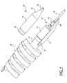
- FIG. 1 there is illustrated a first embodiment of a method and apparatus for weather-proofing in accordance with the invention. While the embodiments of the invention illustrated herein are shown in connection with a coaxial connector for interconnecting to lengths or sections of coaxial cable, the invention may find other applications as well, such as connections between various other types of cables or wires, including individual wires or multiple wires, by various types of connectors or splice connections or the like. The invention may also be useful in connection with weather-proofing of the devices and structures, including, but not limited to, electrical equipment.
- connection 10 between a relatively large diameter coaxial cable 12 and a relatively smaller diameter coaxial cable 14.
- This connection employs a suitable coaxial connector comprising a first connector part 16 of a relatively larger diameter for accommodating the large diameter cable 12 and a second cooperatively interfitting connector portion 18 which is of a smaller diameter for accommodating the relatively smaller cable 14.
- a suitable coaxial connector comprising a first connector part 16 of a relatively larger diameter for accommodating the large diameter cable 12 and a second cooperatively interfitting connector portion 18 which is of a smaller diameter for accommodating the relatively smaller cable 14.
- a foam cast 20 is provided, and in the illustrated embodiment, takes the form of two essentially symmetrical halves 22 and 24 which may be interfitted about the external surface of the connectors 16 and 18.
- the foam cast 20 is of sufficient length or axially extent to completely cover the connectors 16 and 18 and includes additional extensions 24 and 26 at the respective ends thereof for sealingly engaging and overlying a short length of the respective cables 12 and 14 to either side of the connectors 16, 18.
- the connectors and this short length of cable to either side thereof may be referred to as the "connection,” which is to be weather-proofed by the present invention.
- the foam cast 20 preferably comprises a closed cell pre-molded foam member which has an integral, relatively firmer or harder outer skin to provide some rigidity to control its shape during application over the cables 12, 14 and connectors 16, 18.
- the interior part of the foam cast 20 is somewhat more pliable to allow the same to essentially form about the outer contours of the cables 12, 14 and connectors 16, 18 as the two sections or halves 22 and 24 are engaged and pressed thereabout.
- this tape or wrap 30 may comprise a vinyl tape or a fusion tape that amalgamates to itself when stretched and wrapped over the foam cast 20.
- a suitable material for the wrap or tape is an ethylene propylene polymer (EPR) tape with fusion, such as SCOTCHTM, 130C Linerless Rubber Splicing Tape from 3M, Electrical Products Division, Austin, Texas.
- the halves 22 and 24 could be hingedly joined along one edge (not shown) and provided with interfitting latching members (not shown), for example, similar to one of the sets of latches 52, 54 (see below) on an opposite edge.
- EPP Expanded polypropylene
- NEOPOLEN®P from BASF AG
- EPERAN PP from Kaneka Texas Corporation
- Cross linked polyethylene foam from Oletex of South Holland, Illinois or Sentinel Products Corp. of Hyannis, Massachusetts.
- the foregoing method and apparatus possesses a number of advantageous features.
- the provision of the pre-molded foam cast 20 essentially controls the geometry or shape of the outer surface to be wrapped, such that a controlled or predictable quantity of wrapping 30 may be used and even provided in a kit or the like.
- the wrap 30 may be provided in a continuous rolled form with the quantity to be utilized being selected by of the installer.
- the foam cast 20 also helps to lessen the effect of the relatively abrupt transition between the cable and connector sizes (in the embodiment shown in FIG. 1), by providing a relatively gradual or tapered outer surface 32 in this region.
- the foam cast 20 tends to displace air to minimize condensation and air pockets about the connection 10, while at the same time dampening vibration that may result from wind loading or shaking forces.
- the tape 30 seals out moisture or other environmental elements and/or contaminants.
- the method produces a relatively clean, simple and quick installation.
- the foam cast 20 defines and controls the wrap geometry. This allows the connection to be over-wrapped effectively with a controlled quantity of wrapping material in a "football shape" that is generally accepted in the industry.
- an equivalent apparatus and method may be utilized to interconnect cables of the same size, or to weather-proof other devices or structures, without departing from the invention.
- the foam cast 20 and wrap 30 are generally lighter in weight than the prior art butyl tape material.
- the resulting construction is also more aesthetically acceptable since the wrap is generally more consistent and controlled in view of the controlled outer shape of the foam cast's geometry.
- this configuration permits relatively quick and clean removal, in contrast to the relatively sticky and hard to remove butyl rubber tape of the prior art.
- a longitudinal slit down the side of the wrap 30 may allow the foam cast 20 to be safely and easily removed.
- the foam cast is relatively insensitive to variations in temperature facilitating both installation and performance under a variety of environmental conditions. The material of the foam cast will not stick to the hands or equipment of the installer as is the case with the butyl tape, thus further facilitating both installation and removal.
- the foam cast 20 and wrap 30, in the case of a fusion tape is intended to withstand immersion in one meter of water for 24 hours.
- FIG. 2 a second embodiment of the invention is illustrated.
- the weather-proofing is provided the form of a snap-on rigid housing 40 which may be a two-piece assembly.
- the housing 40 comprises two complementary or symmetrical housing halves 42, 44.
- the same type of cable connection 10 as in FIG. 1 is illustrated in FIG. 2, and like reference numerals are used to designate the like parts and components, including cables 12, 14 and respective connectors 16, 18. As in FIG. 1, this may comprise a connection between a larger diameter transmission line cable and a smaller diameter cable such as a jumper.
- the invention as embodied in FIG. 2 may be utilized with like-size cables and connectors or with other devices without departing from the invention.
- the longitudinal or axial extent of the housing 40 is sufficient to cover the entire axial length of the respective connectors 16 and 18 and to extend for some additional distance along the respective cables 12 and 14 so as to completely enclose and seal the connection 10.
- the housing or shell 40 may comprise a relatively rigid, "weatherable" plastic such as Valox 357U or 364, a Polyester/PBT Thermoplastic, from GE Plastics.
- a seal is effected by the provision of a seal of a lower durometer compressible seal or sealing material 50 which extends along respective interfitting edges of the housing halves 42 and 44 as well as along those surfaces which surroundingly engage with the respective cables 12 and 14 upon assembly therewith.
- a suitable material for the compressible seal is Santoprene 101-64, a Thermoplastic Elastomer, from Advanced Elastomer Systems.
- the symmetrical or complementary housing halves 42, 44 are aligned over the connection or device to be sealed and snapped together.
- complementary, aligned sets of snap-tabs 52 and lips 54 may be formed along respective facing and interengaging edges of the respective housing halves 42 and 44.
- the housing halves 42 and 44 may be identical with the top housing half 42 as shown in FIG. 2 being rotated 180° about the longitudinal axis defined by the cables 12 and 14 relative to the housing half 44.
- a quantity of foam material 60 provided in the hollow interior of the housing 40 is pressed into contact with the connectors 16 and 18 to displace air pockets, thereby discouraging condensation, fungus, or mildew growth or the like about the connectors.
- This foam materials also contributes to dampening of vibrations, thereby helping to maintain the recommended torque or connection forces between the connectors 16 and 18.
- a relatively soft, closed cell foam may be used for this purpose, so as to closely conform to the external surfaces of the connectors and eliminate air pockets.
- the invention as embodied in FIG. 2 is also re-enterable and re-useable, by the expedient of releasing the releasable snap-locked engagement (e.g. tabs 52 and lips 54) between the respective housing halves 42 and 44.
- Installation and removal of the housing halves 42 and 44 is relatively simple and rapid, by engaging or disengaging the respective interlocking snap-tabs and cooperating lips 52 and 54 manually.
- a minimal number of parts and components are utilized, namely, only the housing halves 42 and 44, the seal 50, and a quantity of foam material 60.
- This arrangement is also designed to withstand immersion in one meter of water for 24 hours.
- the embodiment of FIG. 2 is relatively insensitive to variations in temperature either during installation or removal or in service.
- housing halves 42, 44 may be hingedly joined along one edge, and have the tabs and lips 52, 54 only along the opposite edge, to form a "clamshell" type of configuration.
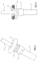
- FIGS. 3 and 4 yet another embodiment of the invention is illustrated.
- an elongated extruded tube 70 of an elastomeric compound is stretched to an inner diameter that is larger than the maximum outer diameter of the connection or other device to be covered.
- a similar connection between a larger diameter cable 112 and a smaller diameter cable 113, utilizing cooperating interengaged connector elements 116, 118 is illustrated.
- This connection is designated generally by reference numeral 110.
- the elastomeric compound of the tube 70 may include such materials such as: 1) a Thermoplastic material from Teknor Apex Co. of Pawtucket, Rhode Island; or 2) A silicone material from ARLON Silicone Technologies Division of Delaware. These materials can be stretched as described and illustrated herein and then shrink down to a smaller recovery diameter.
- the recovery diameter of the tube 70 is preferably somewhat smaller than the minimum diameter of the connection or device to be covered.
- one end of the tube 70 closely engages the smaller diameter cable 114 in the example shown in FIGS. 3 and 4.
- the extruded tube 70 is rolled into a generally toroidal or doughnut shape to provide a compact and convenient package for later use in the field.
- the rolled-up tube 70 is placed over one end of the connection or other device. In FIGS. 3 and 4 this comprises the smaller diameter cable 114.
- the tube may then be unrolled by toward the opposite cable 112.
- a toroidal core (not shown), for example, of corrugated material may be used to roll-up the tube.
- the elastomeric tube shrinks down toward its recovery diameter so as to generally conform to the external shape of the connection or other device, including the external configuration of the connectors 116 and 118 and of the cable 112. This acts both to seal the device against the environmental elements or contaminants as well as removing air voids or the like in which condensation might otherwise form.
- the elastomeric material also acts to dampen vibrations that might result from wind loading or shaking forces.
- the toroidal or doughnut shaped core 74 may then be discarded or may be maintained as an integral part of the tube 70 whereupon it can be used to unroll the tube for re-entry and/or re-use of the tube 70.
- FIGS. 3 and 4 may be re-entered by producing a longitudinal slit down a side of the tube 70, in which case, however, it would not be re-used.
- This apparatus and method is believed to be more compact, quicker and easier to install in the field than the cold shrink wrap procedure described hereinabove wherein a cold shrink is carried on an elongated corrugated tube.
- the embodiment of FIGS. 3 and 4 is also designed to withstand immersion in one meter of water for 24 hours.
Landscapes
- Engineering & Computer Science (AREA)
- Manufacturing & Machinery (AREA)
- Cable Accessories (AREA)
- Connector Housings Or Holding Contact Members (AREA)
- Multi-Conductor Connections (AREA)
Applications Claiming Priority (2)
| Application Number | Priority Date | Filing Date | Title |
|---|---|---|---|
| US80768 | 1979-10-01 | ||
| US8076898A | 1998-05-18 | 1998-05-18 |
Publications (1)
| Publication Number | Publication Date |
|---|---|
| EP0959537A1 true EP0959537A1 (fr) | 1999-11-24 |
Family
ID=22159508
Family Applications (1)
| Application Number | Title | Priority Date | Filing Date |
|---|---|---|---|
| EP99107903A Withdrawn EP0959537A1 (fr) | 1998-05-18 | 1999-04-21 | Méthode et appareil pour la protection contre des intempéries pour des composants tels que connecteurs de câble |
Country Status (5)
| Country | Link |
|---|---|
| EP (1) | EP0959537A1 (fr) |
| JP (1) | JPH11345639A (fr) |
| CN (1) | CN1236210A (fr) |
| AU (1) | AU2396499A (fr) |
| BR (1) | BR9902090A (fr) |
Cited By (3)
| Publication number | Priority date | Publication date | Assignee | Title |
|---|---|---|---|---|
| WO2007087470A3 (fr) * | 2006-01-27 | 2008-01-10 | Gen Patent Llc | Dispositif a ondes de choc ameliore |
| CN103943401A (zh) * | 2014-04-28 | 2014-07-23 | 国家电网公司 | 一种用于户外电力设施操作箱垂直输出轴的防风机构 |
| US20240006866A1 (en) * | 2022-06-30 | 2024-01-04 | 3M Innovative Properties Company | Covering tool and covering method |
Families Citing this family (3)
| Publication number | Priority date | Publication date | Assignee | Title |
|---|---|---|---|---|
| US7307219B1 (en) * | 2006-06-07 | 2007-12-11 | 3M Innovative Properties Company | Closure housing for sealing |
| KR100946178B1 (ko) | 2006-09-05 | 2010-03-08 | 주식회사 에이스테크놀로지 | 알에프 커넥터 |
| CN115603106A (zh) * | 2022-10-13 | 2023-01-13 | 玉林创格科技有限公司(Cn) | 注塑发泡一体连接式线束 |
Citations (7)
| Publication number | Priority date | Publication date | Assignee | Title |
|---|---|---|---|---|
| US2967795A (en) * | 1955-10-18 | 1961-01-10 | Minnesota Mining & Mfg | Protection of wire-splices |
| US4135587A (en) * | 1975-12-08 | 1979-01-23 | Raychem Corporation | Cases for enclosing substrates |
| US4376231A (en) * | 1980-01-14 | 1983-03-08 | Bell Telephone Laboratories, Incorporated | Communication cable sealed with a re-enterable sealing tape |
| US4648919A (en) * | 1984-09-18 | 1987-03-10 | Raychem Corp. | Protection of cable splice |
| US4818310A (en) * | 1987-05-05 | 1989-04-04 | Bell South Corporation | Pressurized cable splice closure apparatus and method |
| US4859809A (en) * | 1988-04-27 | 1989-08-22 | Raychem Corporation | Splice case |
| US5111001A (en) * | 1990-04-13 | 1992-05-05 | Raychem Corporation | Splice case |
-
1999
- 1999-04-21 EP EP99107903A patent/EP0959537A1/fr not_active Withdrawn
- 1999-04-26 AU AU23964/99A patent/AU2396499A/en not_active Abandoned
- 1999-05-13 JP JP13236999A patent/JPH11345639A/ja not_active Withdrawn
- 1999-05-18 BR BR9902090-4A patent/BR9902090A/pt not_active Application Discontinuation
- 1999-05-18 CN CN 99106656 patent/CN1236210A/zh active Pending
Patent Citations (7)
| Publication number | Priority date | Publication date | Assignee | Title |
|---|---|---|---|---|
| US2967795A (en) * | 1955-10-18 | 1961-01-10 | Minnesota Mining & Mfg | Protection of wire-splices |
| US4135587A (en) * | 1975-12-08 | 1979-01-23 | Raychem Corporation | Cases for enclosing substrates |
| US4376231A (en) * | 1980-01-14 | 1983-03-08 | Bell Telephone Laboratories, Incorporated | Communication cable sealed with a re-enterable sealing tape |
| US4648919A (en) * | 1984-09-18 | 1987-03-10 | Raychem Corp. | Protection of cable splice |
| US4818310A (en) * | 1987-05-05 | 1989-04-04 | Bell South Corporation | Pressurized cable splice closure apparatus and method |
| US4859809A (en) * | 1988-04-27 | 1989-08-22 | Raychem Corporation | Splice case |
| US5111001A (en) * | 1990-04-13 | 1992-05-05 | Raychem Corporation | Splice case |
Cited By (3)
| Publication number | Priority date | Publication date | Assignee | Title |
|---|---|---|---|---|
| WO2007087470A3 (fr) * | 2006-01-27 | 2008-01-10 | Gen Patent Llc | Dispositif a ondes de choc ameliore |
| CN103943401A (zh) * | 2014-04-28 | 2014-07-23 | 国家电网公司 | 一种用于户外电力设施操作箱垂直输出轴的防风机构 |
| US20240006866A1 (en) * | 2022-06-30 | 2024-01-04 | 3M Innovative Properties Company | Covering tool and covering method |
Also Published As
| Publication number | Publication date |
|---|---|
| CN1236210A (zh) | 1999-11-24 |
| BR9902090A (pt) | 2000-02-22 |
| AU2396499A (en) | 1999-11-25 |
| JPH11345639A (ja) | 1999-12-14 |
Similar Documents
| Publication | Publication Date | Title |
|---|---|---|
| US4810829A (en) | Cable closure | |
| EP2497171B1 (fr) | Ensembles gaines de câble enveloppantes | |
| US6706968B2 (en) | Environmentally sealed wrap-around sleeves having a longitudinal sealant chamber | |
| JP2934492B2 (ja) | 接続部のエンクロージャ | |
| US4569868A (en) | Heat-recoverable article | |
| US20060042814A1 (en) | Sealing member for enclosures | |
| KR100885333B1 (ko) | 연장가능한 바디부를 가진 랩 어라운드 케이블 슬리브 및이의 제조 방법 | |
| US20090283294A1 (en) | Cover Assembly for Cables and Electrical Connections and Methods for Using the Same | |
| WO2011005371A1 (fr) | Élément d'obturation | |
| EP0525071A1 (fr) | Manchon en elastomere de forme recuperable a froid et procede d'installation et d'utilisation. | |
| WO2007008294A1 (fr) | Élément d’étanchéite destiné à un orifice d'entrée | |
| HK1007360B (en) | Elastomeric covering having conformable interior | |
| US5055636A (en) | Sealed reenterable splice enclosure | |
| AU2001253680A1 (en) | Wrap-around cable sleeves having an expandable body portion and methods of making same | |
| AU2396499A (en) | Weather-proofing method and apparatus for components such as cable connectors | |
| JP2005539470A (ja) | 応力除去部を含むケーブルシーリングカバー | |
| AU633864B2 (en) | Splice closures | |
| US5977484A (en) | Low-odor dual element cable connection cover | |
| EP1058364A1 (fr) | Appareillage de protection des intempéries pour un connecteur | |
| PL188021B1 (pl) | Oprawa zaciskowa, zwłaszcza do kabli | |
| US5801333A (en) | Low-odor single element cable connection cover | |
| US6455779B1 (en) | Dual element cable connection cover | |
| CA1222552A (fr) | Ensemble d'enveloppe et de detendeur pour epissures |
Legal Events
| Date | Code | Title | Description |
|---|---|---|---|
| PUAI | Public reference made under article 153(3) epc to a published international application that has entered the european phase |
Free format text: ORIGINAL CODE: 0009012 |
|
| AK | Designated contracting states |
Kind code of ref document: A1 Designated state(s): BE CH DE FI FR GB LI |
|
| AX | Request for extension of the european patent |
Free format text: AL;LT;LV;MK;RO;SI |
|
| 17P | Request for examination filed |
Effective date: 20000427 |
|
| AKX | Designation fees paid |
Free format text: BE CH DE FI FR GB LI |
|
| 17Q | First examination report despatched |
Effective date: 20000724 |
|
| STAA | Information on the status of an ep patent application or granted ep patent |
Free format text: STATUS: THE APPLICATION IS DEEMED TO BE WITHDRAWN |
|
| 18D | Application deemed to be withdrawn |
Effective date: 20011120 |