EP0959579A2 - Optischer Einfüge/Abzweig-Multiplexer/Demultiplexer - Google Patents
Optischer Einfüge/Abzweig-Multiplexer/Demultiplexer Download PDFInfo
- Publication number
- EP0959579A2 EP0959579A2 EP99303868A EP99303868A EP0959579A2 EP 0959579 A2 EP0959579 A2 EP 0959579A2 EP 99303868 A EP99303868 A EP 99303868A EP 99303868 A EP99303868 A EP 99303868A EP 0959579 A2 EP0959579 A2 EP 0959579A2
- Authority
- EP
- European Patent Office
- Prior art keywords
- optical
- input
- signals
- output
- signal
- Prior art date
- Legal status (The legal status is an assumption and is not a legal conclusion. Google has not performed a legal analysis and makes no representation as to the accuracy of the status listed.)
- Ceased
Links
- 230000003287 optical effect Effects 0.000 title claims abstract description 209
- 239000000835 fiber Substances 0.000 claims abstract description 38
- 238000013507 mapping Methods 0.000 claims abstract description 9
- 230000005693 optoelectronics Effects 0.000 claims description 27
- 238000006243 chemical reaction Methods 0.000 claims description 8
- 238000012423 maintenance Methods 0.000 claims description 2
- 230000005540 biological transmission Effects 0.000 description 9
- 238000000034 method Methods 0.000 description 9
- 238000011144 upstream manufacturing Methods 0.000 description 7
- 230000001276 controlling effect Effects 0.000 description 6
- 239000013307 optical fiber Substances 0.000 description 5
- 238000001228 spectrum Methods 0.000 description 5
- 238000010586 diagram Methods 0.000 description 3
- 230000001360 synchronised effect Effects 0.000 description 3
- 230000003321 amplification Effects 0.000 description 2
- 238000004891 communication Methods 0.000 description 2
- 230000001419 dependent effect Effects 0.000 description 2
- 230000000694 effects Effects 0.000 description 2
- 230000006870 function Effects 0.000 description 2
- 238000003199 nucleic acid amplification method Methods 0.000 description 2
- 230000011664 signaling Effects 0.000 description 2
- 206010035148 Plague Diseases 0.000 description 1
- 241000607479 Yersinia pestis Species 0.000 description 1
- 230000009471 action Effects 0.000 description 1
- 230000008901 benefit Effects 0.000 description 1
- 238000007796 conventional method Methods 0.000 description 1
- 238000013461 design Methods 0.000 description 1
- 239000006185 dispersion Substances 0.000 description 1
- 238000002955 isolation Methods 0.000 description 1
- 238000005259 measurement Methods 0.000 description 1
- 230000007246 mechanism Effects 0.000 description 1
- 238000012986 modification Methods 0.000 description 1
- 230000004048 modification Effects 0.000 description 1
- 230000001105 regulatory effect Effects 0.000 description 1
- 230000035945 sensitivity Effects 0.000 description 1
- 230000003595 spectral effect Effects 0.000 description 1
- 230000032258 transport Effects 0.000 description 1
- 238000012795 verification Methods 0.000 description 1
Images


Classifications
-
- H—ELECTRICITY
- H04—ELECTRIC COMMUNICATION TECHNIQUE
- H04J—MULTIPLEX COMMUNICATION
- H04J14/00—Optical multiplex systems
- H04J14/02—Wavelength-division multiplex systems
- H04J14/0221—Power control, e.g. to keep the total optical power constant
-
- H—ELECTRICITY
- H04—ELECTRIC COMMUNICATION TECHNIQUE
- H04J—MULTIPLEX COMMUNICATION
- H04J14/00—Optical multiplex systems
- H04J14/02—Wavelength-division multiplex systems
- H04J14/0201—Add-and-drop multiplexing
- H04J14/0202—Arrangements therefor
- H04J14/021—Reconfigurable arrangements, e.g. reconfigurable optical add/drop multiplexers [ROADM] or tunable optical add/drop multiplexers [TOADM]
- H04J14/0212—Reconfigurable arrangements, e.g. reconfigurable optical add/drop multiplexers [ROADM] or tunable optical add/drop multiplexers [TOADM] using optical switches or wavelength selective switches [WSS]
-
- H—ELECTRICITY
- H04—ELECTRIC COMMUNICATION TECHNIQUE
- H04Q—SELECTING
- H04Q11/00—Selecting arrangements for multiplex systems
- H04Q11/0001—Selecting arrangements for multiplex systems using optical switching
- H04Q11/0005—Switch and router aspects
-
- H—ELECTRICITY
- H04—ELECTRIC COMMUNICATION TECHNIQUE
- H04Q—SELECTING
- H04Q11/00—Selecting arrangements for multiplex systems
- H04Q11/0001—Selecting arrangements for multiplex systems using optical switching
- H04Q11/0005—Switch and router aspects
- H04Q2011/0007—Construction
- H04Q2011/0016—Construction using wavelength multiplexing or demultiplexing
-
- H—ELECTRICITY
- H04—ELECTRIC COMMUNICATION TECHNIQUE
- H04Q—SELECTING
- H04Q11/00—Selecting arrangements for multiplex systems
- H04Q11/0001—Selecting arrangements for multiplex systems using optical switching
- H04Q11/0005—Switch and router aspects
- H04Q2011/0007—Construction
- H04Q2011/0024—Construction using space switching
-
- H—ELECTRICITY
- H04—ELECTRIC COMMUNICATION TECHNIQUE
- H04Q—SELECTING
- H04Q11/00—Selecting arrangements for multiplex systems
- H04Q11/0001—Selecting arrangements for multiplex systems using optical switching
- H04Q11/0005—Switch and router aspects
- H04Q2011/0037—Operation
- H04Q2011/0039—Electrical control
-
- H—ELECTRICITY
- H04—ELECTRIC COMMUNICATION TECHNIQUE
- H04Q—SELECTING
- H04Q11/00—Selecting arrangements for multiplex systems
- H04Q11/0001—Selecting arrangements for multiplex systems using optical switching
- H04Q11/0062—Network aspects
- H04Q2011/0069—Network aspects using dedicated optical channels
Definitions
- This invention relates to optical transmission systems in general, and specifically to a method and apparatus for switching, modulating and attenuating optical signals in fiber optic networks employing wavelength division multiplexing.
- WDM wavelength division multiplexed
- DWDM dense WDM
- the distance between optical terminals of the optical fiber transmission system is limited by transmitter power, receiver sensitivity, and loss and dispersion considerations. Where the distance between end points of an optical fiber transmission system exceeds the maximum distance between optical terminals, amplifiers (also known as repeaters) are provided. As the data rates of optical fiber transmission systems enter the 10 Gigabits per second (Gbps) to 40 Gbps range per channel, it would be prohibitively expensive to convert a multi-wavelength optical input signal into multiple electronic signals prior to amplification and reconverting the amplified electronic signals to a WDM output signal. Therefore, it preferable to use purely optical amplifiers to perform amplification of channels, thereby circumventing the huge potential cost of electronic-to-optical and optical-to-electronic conversion.
- Gbps Gigabits per second
- optical add/drop multiplexer/demultiplexers for introducing (adding) supplementary optical channels coming from another part of the network to the stream of traffic between two optical terminals.
- the optical ADM also serves to divert (drop) optical channels from the main signal path on the fiber to another part of the network.
- a selectable but predetermined routing pattern is executed between pairs of input and output channels of the component, i.e., the ADM acts as a switch.
- the initial (and usually optimal) relative intensity of wavelengths in the power spectrum of a WDM or DWDM signal is not preserved by amplifiers that provide signals to the ADM, thereby reducing the effective maximum distance between amplifiers and causing undesirable effects such as increased bit-error rate.
- gain tilt affects the power spectrum of a WDM signal, prompt action must therefore be taken to equalize or restore its optimal spectral shape.
- faults occurring upstream cause a loss of data in the ADM, but it is difficult for the component to differentiate between a non-existent signal at its input and one that has been deliberately set to zero intensity, especially since an optical ADM has no visibility into the data due to the absence of optoelectronic conversion.
- the invention may be summarised according to a first broad aspect as an add/drop multiplexer/demultiplexer (ADM) for connection in a fiber optic network adapted to carry WDM optical signals, the ADM comprising first and second optical ports for connection to the network; a wavelength demultiplexer connected to the first port and a wavelength multiplexer connected to the second port; a plurality of optical signal lines extending between the demultiplexer and the multiplexer for carrying respective demultiplexed optical signals; a plurality of optical switches connected respectively to the plurality of optical signals lines, each switch also being connected to a respective one of a plurality of add signal lines and to a respective one of a plurality of drop signal lines; a plurality of optoelectronic converters respectively connected to the plurality of optical signal lines; a controller electronically connected to the optoelectronic converters and the optical switches for detecting dither signals in the demultiplexed optical signals and controlling the optical switches according to instructions encoded in the detected dither signals.
- the invention may be summarised according to a second broad aspect as an add/drop multiplexer/demultiplexer (ADM) for connection in a fiber optic network adapted to carry wavelength division multiplexed (WDM) optical signals, the ADM comprising a wavelength demultiplexer having an input port for connection to the network and a plurality of output ports respectively connected to a plurality of optical input signal lines for carrying respective demultiplexed optical input signals; a wavelength multiplexer having an output port for connection to the network and a plurality of input ports respectively connected to a plurality of optical output signal lines for carrying respective demultiplexed optical output signals; a plurality of controllable optical switches, each having a first input connected to a respective one of the plurality of optical input signal lines, a first output connected to a respective one of the plurality of optical output signal lines, a second input connected to a respective one of a plurality of add signal lines and a second output connected to a respective one of a plurality of drop signal lines; a plurality of
- the invention may be summarised as a method of controlling optical signals arriving at an add/drop multiplexer/demultiplexer (ADM) connected in a fiber optic network, the method comprising detecting dither signals respectively embedded in the optical signals, and controlling the optical signals according to the detected dither signals.
- ADM add/drop multiplexer/demultiplexer
- the invention may be summarised according to a fourth broad aspect as a method of switching optical signals arriving at an add/drop multiplexer/demultiplexer (ADM) connected in a fiber optic network, the method comprising encoding switching instructions for each optical signal as a respective dither signal; embedding the dither signals respectively within the optical signals; detecting the dither signals at the ADM; decoding the switching instructions from the dither signals; and switching the optical signals arriving at the ADM according to the decoded switching instructions.
- ADM add/drop multiplexer/demultiplexer
- the present invention may be summarised as an optical router for use in a fiber optic network adapted to carry wavelength division multiplexed (WDM) optical signals, the router comprising a plurality of input ports for connection to the network and for carrying respective optical input signals; a plurality of output ports for connection to the network and for carrying respective optical output signals; demultiplexing means for separating the optical input signals into respective sets of demultiplexed optical input signals; multiplexing means for forming the output WDM optical signals from respective sets of demultiplexed optical output signals; switch means for selectively interconnecting the demultiplexed optical input signals to the demultiplexed optical output signals; and control means for controlling the switch according to instructions provided by dither signals embedded within the demultiplexed optical input or output signals.
- WDM wavelength division multiplexed
- the controller is typically realised by a digital signal processor running software.
- the preferred embodiments of the present invention therefore generally mitigate or obviate one or more of the disadvantages associated with the prior art.
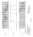
- FIG. 1 depicts an exemplary bi-directional fiber optic communication system comprising two terminal nodes 10,15 with respective optical transmit ports 11,16 and optical receive ports 12,17.
- the transmit port of either node is joined to the receive port of the other node by a series of network components and fiber optic links.
- a first span L1 originating at the transmit port 11 of node 10 terminates at a unidirectional multi-wavelength optical repeater (MOR) 20 and carries a wavelength-division multiplexed (WDM) signal B.
- MOR multi-wavelength optical repeater
- WDM wavelength-division multiplexed
- Another span L2 transports signal B from the MOR 20 to a unidirectional add/drop multiplexer/demultiplexer (ADM) 30.
- ADM add/drop multiplexer/demultiplexer
- the ADM 30 is connected to the receive port 17 of node 15 by fiber optic segments L3 and L4 carrying a WDM signal C and intercepted by another MOR 24.
- the ADM 30 is also joined to a plurality (L) of optical transmitters 70 by optical "add lines” L5 carrying signals A1,A2,...,AL, and to a plurality (L) of optical receivers 80 by optical "drop lines" L6 transporting signals D1,D2,...,DL.
- the transmit port 16 of node 15 is connected to an ADM 35 via two fiber optic segments L7 and L8 carrying a WDM signal B' and linked by an MOR 26.
- the ADM 35 is connected to another MOR 22 by a fiber optic link L9 carrying a WDM signal C'.
- the ADM 35 is also joined to a plurality (L) of optical transmitters 75 by optical add lines L11 carrying signals A'1,A'2,...,A'L, and to a plurality (L) of optical receivers 85 by optical drop lines L12 transporting signals D'1, D'2 D'L.
- the MOR 22 is connected to the receive port 12 of node 10 by a fiber optic link L10 transporting signal C'.
- node 10 In the illustrated embodiment, there are two directions of traffic flow.
- node 10 In one direction, node 10 generates the WDM optical signal B which is sent from its transmit port 11 in the direction of node 15.
- signal B is retransmitted and usually amplified by MOR 20 and enters ADM 30, which also accepts optical add signals A1,A2,...,AL arriving from transmitters 70.
- ADM 30 performs a switching operation and outputs signal C, headed for the receive port 17 of node 15 via MOR 24, in addition to drop signals D1,D2,...,DL headed for optical receivers 80.
- WDM signal B' transmitted from the transmit port 16 of node 15, reaching ADM 35 via MOR 26.
- ADM 35 also accepts add signals A'1,A'2,...,A'L from optical transmitters 75, and outputs WDM signal C' that passes through MOR 22 on its way to the receive port 12 of node 10.
- WDM signal C' that passes through MOR 22 on its way to the receive port 12 of node 10.
- the ADM 35 outputs drop signals D'1,D'2,...,D'L that are captured by respective optical receivers 85.
- FIG. 2 shows in more detail the unidirectional ADM 30 in accordance with the present invention.
- the optical segment L2 carrying WDM signal B is connected to an input port 301 of an optical demultiplexer 300.
- the demultiplexer 300 also comprises a plurality (L) of output ports 302,303,...,304, from which extend respective demultiplexed optical signal lines L13 (and others not shown) carrying respective demultiplexed optical signals B1,B2,...,BL.
- L may be as large as desired, although powers of two ranging from 2 to 32 are most useful.
- Signal line L13 is intercepted by an optoelectronic converter 100 before reaching one input of a two-input, two-output (2x2) optical switch 105.
- the converter 100 is connected to a controller 200 by an electronic signal line L19 carrying a feedforward signal F1.
- the second input of the switch 105 is one of the optical add lines L5, carrying optical add signal Al.
- the switch 105 has two optical output signal lines, namely, a signal line L15 transporting a signal El, and one of the drop lines L6, carrying drop signal D1.
- the switch 105 is controlled by an electronic control signal H1 on signal line L20 from the controller 200.
- the controller 200 is preferably a digital signal processor running a software algorithm, although an analog circuit can be employed to achieve the functions described hereunder.
- Signal line L15 at the output of switch 105 is intercepted by a modulator 110 producing a signal M1 that enters an attenuator 115, from which extends an optical signal line L17 carrying a signal C1.
- the modulator 110 and attenuator 115 are controlled by respective electronic control signals J1,K1 on respective signal lines L21,L22 leading from the controller 200.
- Signal line L17 at the output of the attenuator 115 is intercepted by another optoelectronic converter 120.
- the converter 120 is linked to the controller 200 by an electronic signal line L23 carrying a feedback signal G1, and outputs an optical signal line L18, still carrying signal C1, to an optical input 352 of an optical multiplexer 350.
- the multiplexer 350 has multiple optical input ports 352,353,...,354 transporting respective signals C1,C2,...,CL, and one optical output port 351, which carries WDM signal C on signal line L3.
- An optical signal path leading from each of the demultiplexer output ports 303,...,304 to an associated multiplexer input port 353,...,354 exists, and is identical to the one described above leading from demultiplexer output port 302 to multiplexer input port 352.
- each such path involves a corresponding add line, drop line, switch, modulator, attenuator, and pair of optoelectronic converters.
- all these components are electronically connected to the single, centralized controller 200.
- signal B is typically a WDM optical signal carrying L individual high-speed optical signals B1,B2,...,BL.
- These individual signals are separated by the optical demultiplexer 300, and preferably consist of frames of digital data arranged according to a synchronous transmission standard such as SONET (synchronous optical network) or SDH (synchronous digital hierarchy).
- SONET synchronous optical network
- SDH synchronous digital hierarchy
- signal B1 it is tapped by the optoelectronic converter 100, meaning that a small percentage of the optical power of signal B1 is converted into analog electronic format by, for example, a PIN diode.
- the analog electronic signal is sampled and converted to a digital electronic signal by an analog-to-digital converter.
- This digital electronic representation of optical signal B1 is in fact the feedforward signal F1 that is input to the controller 200 along signal line L19.
- the switch 105 executes one of two possible mappings.
- the "straight-through” mapping means routes the incoming signal from the input port to the output port, i.e., signal B1 to signal El.
- the "cross-over” mapping means routes the incoming signal from the input port to the drop port, and the add signal from the add port to the output port, i.e., E1 to D1 and A1 to E1. Selection of the input-output mapping to be executed is achieved through electronic control signal H1 from the controller 200.
- the modulator 110 subsequently changes signal El into signal M1 by adding or removing a low-frequency, low-amplitude control signal, as will be described hereunder. Control of the modulator is achieved via electronic control signal J1.
- the attenuator 115 is instructed to apply a controllable amount of attenuation to signal M1 via electronic control signal K1 from the controller 200, thereby yielding optical signal C1 that passes through the converter 120 on its way to the multiplexer 350.
- the converter 120 taps a small amount of optical energy from signal C1, producing a digital electronic version G1 that is fed back to the controller 200 along signal line L23.
- the multiplexer 350 recombines the individual optical signals C1,C2,...,CL in d known way to give WDM signal C on optical signal line L3.
- the feedforward and feedback electronic signals from the optoelectronic converters 100,120 are vital to controlling operation of the controller 200.
- the feedforward control signals are interpreted by the controller.
- the feedback control signals are useful for verification purposes (e.g., after switching) or for extracting information from the add lines once they have been switched.
- feedforward signal F1 and feedback signal G1 are electronic representations of high-speed (possibly several dozen Gbps) optical signals B1 and C1, respectively.
- data rate of the order of 1 Mbps
- special techniques are required to embed channel-dependent control information in each of the signals B1,B2,...,BL, C1,C2,...,CL.
- FIG. 3 in which is shown an arbitrary high-frequency optical signal s(t), consisting of pulses of light.
- the dither signal is shown as being a digital signal d(t), which is scaled by a modulation depth constant "M” and subtracted from the initial signal s(t) to give the resultant, "dithered" signal r(t).
- the peak optical power Po is a parameter that is dependent on the type of optical signalling used in the system.
- an optical signal may have been dithered at a known modulation depth "M" by a transmitter upstream from the ADM. If the corresponding received signal at the ADM is B1, then a low pass filter can be applied to the digital signal F1 in order to extract the embedded dither. This yields a pure low-frequency dither signal of a certain detected amplitude ⁇ . The received signal amplitude is therefore estimated to be ⁇ /M and is compared with the peak known amplitude Po used in the system. An accurate estimate of signal power can thus be obtained irrespective of noise on the received signal, since the dither signal is not random and can be extracted by correlating F1 with known sequences.
- a low value of signal power on a given channel may indicate a significant loss along the channel.
- a conventional method of regulating the power of such an affected channel is to feed signal F1 along a "back channel" to the point of transmission, upstream from the ADM, and then to adjust the power of signal B1.
- this invention provides power control functionality directly at the ADM 30 using the controller 200.
- the attenuators (115 and those not shown in each of the other signal paths) can be controlled based on the estimated power of all the individual optical channels, thereby to equalize the optical power spectrum of WDM signal C according to a desired shape.
- the attenuator 115 can be used to controllably attenuate the power of optical signal C1 so as to reduce the impact of abrupt power variations of the output signal level on the receivers 80 and MOR 24 during an add/drop operation, i.e., when the switch operates in the cross-over mapping.
- the present invention provides programmable adding and dropping of channels.
- the controller 200 can detect routing instructions embedded in a dither signal superimposed on signal B1, and executes a program stored in its memory which controls the operation of switch 105.
- the switch 105 can also be controlled according to routing instructions contained in a dither signal superimposed on signal A1. In this case, the switch 105 may have to temporarily execute a cross-over mapping so as to allow the controller 200 to access the dither signal present on add signal A1.
- operation of the switch 105 can be autonomously controlled according to the strength of signal B1 estimated using the above-identified method. If the estimated signal power of B1 is lower than a given threshold, the channel may have to be routed (dropped) to another part of the network. In the prior art, switching of signals based on power measurements could not be effected at the ADM in real time.
- the modulator 110 it can be instructed by the controller 200 to add dither to (or remove dither from) signal E1 in order to satisfy downstream transmission equipment requirements. For example, if the equipment installed downstream from the ADM relies on a dither signal for executing switching or other control functions, then the ADM can be instructed via the dedicated control channel to add an appropriate dither signal to E1.
- the transmission equipment upstream from the ADM need not be upgraded to accommodate downstream equipment, thereby ensuring interoperability between different equipment manufacturers.
- dither removal may be necessary and can be achieved in two convenient ways.
- the dither signal superimposed on an individual optical input signal may contain a code instructing the controller 200 to instruct the appropriate modulator to add a phase-inverted "cancellation" dither onto the output signal.
- such instructions for the controller may be transmitted to the ADM via the dedicated control channel.
- the dedicated control channel can also be used to override portions of the controller software algorithm, thereby permitting a remote network administrator to "log in” to the ADM and reprogram the controller.
- status and maintenance information can be transmitted from the ADM, e.g., to indicate a switch failure.
- the dither signal extracted from feedback signal G1 can be matched against a list of acceptable sequences for routed channels, identifying whether the switch has performed the correct routing, and sending an appropriate message to an external network element.
- the data rate of the control channel in either direction is preferably on the order of 1 Mbps.
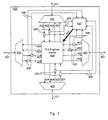
- FIG. 4 shows an alternate embodiment of an inventive ADM 400 configured as a WDM router in a star network. It interfaces with bi-directional fibers 401 via respective bi-directional optical multiplexers 402.
- the four fibers 401 may constitute a main signal path and a protected (redundant) signal path through the ADM.
- each of the individual fibers 401 may carry independent traffic to and from distinct parts of the network.
- Each bi-directional fiber 401 carries two respective downstream signals 403 and two respective upstream signals 404.
- the downstream signals 403 are intercepted by respective optoelectronic converters 405, which provide electronic signals 406 to a centralized controller 407 of the ADM.
- the downstream signals 403 enter an 8x8 optical switch 408, from which emerge the upstream signals 404.
- the switch 408 is controlled by the controller 407 via a control line 410.
- the switch 408 routes its eight inputs to its eight outputs in a combination that is specified by the controller 407.
- the routing information is encoded into dither signals embedded in the downstream signals 403, and decoded by the controller 407.
- modulators, attenuators and additional optoelectronic converters that may intercept the downstream signals 404.
- both the controller (200 or 407) and the dither signal could be analog instead of digital.
- the controller may comprise multiple bandpass filters that route incoming optical channels depending on the combination of frequencies present in their corresponding dither signals, akin to the multiple-frequency tones used in encoding and decoding dialled telephone digits.
Landscapes
- Engineering & Computer Science (AREA)
- Computer Networks & Wireless Communication (AREA)
- Signal Processing (AREA)
- Optical Communication System (AREA)
- Use Of Switch Circuits For Exchanges And Methods Of Control Of Multiplex Exchanges (AREA)
Applications Claiming Priority (2)
| Application Number | Priority Date | Filing Date | Title |
|---|---|---|---|
| US81666 | 1998-05-20 | ||
| US09/081,666 US5959749A (en) | 1998-05-20 | 1998-05-20 | Optical add/drop multiplexer/demultiplexer |
Publications (2)
| Publication Number | Publication Date |
|---|---|
| EP0959579A2 true EP0959579A2 (de) | 1999-11-24 |
| EP0959579A3 EP0959579A3 (de) | 2003-05-14 |
Family
ID=29709323
Family Applications (1)
| Application Number | Title | Priority Date | Filing Date |
|---|---|---|---|
| EP99303868A Ceased EP0959579A3 (de) | 1998-05-20 | 1999-05-18 | Optischer Einfüge/Abzweig-Multiplexer/Demultiplexer |
Country Status (3)
| Country | Link |
|---|---|
| US (2) | US5959749A (de) |
| EP (1) | EP0959579A3 (de) |
| CA (1) | CA2272023C (de) |
Cited By (7)
| Publication number | Priority date | Publication date | Assignee | Title |
|---|---|---|---|---|
| US6288812B1 (en) | 2000-11-03 | 2001-09-11 | Seneca Networks | Bidirectional WDM optical communication network with optical bridge between bidirectional optical waveguides |
| GB2362525A (en) * | 2000-05-18 | 2001-11-21 | Marconi Comm Ltd | Optical power equalizer with attenuators |
| WO2001091349A3 (en) * | 2000-05-23 | 2002-09-12 | Novera Optics Inc | Channel equalizer with acousto-optic variable attenuators |
| WO2002098038A1 (en) * | 2001-05-28 | 2002-12-05 | Lnl Technologies Canada Inc. | Integrated optical add-drop multiplexer (oadm) using optical waveguide mirrors and multiplexer/demultiplexer |
| WO2003028261A2 (en) | 2001-09-27 | 2003-04-03 | Tropic Networks Inc. | Topology discovery in optical wdm networks |
| EP1158713A3 (de) * | 2000-03-31 | 2003-10-22 | Nortel Networks Limited | Optische Wellenform zur Verwendung in einem DWDM optischen Netzwek und Vorrichtungen zur seiner Erzeugung und Verarbeitung |
| GB2542807A (en) * | 2015-09-30 | 2017-04-05 | British Telecomm | Communications network |
Families Citing this family (105)
| Publication number | Priority date | Publication date | Assignee | Title |
|---|---|---|---|---|
| SE506748C2 (sv) * | 1995-06-26 | 1998-02-09 | Ericsson Telefon Ab L M | Förfarande och anordning för att borttaga och addera kanaler i en optisk multiplexor |
| GB9516017D0 (en) * | 1995-08-04 | 1995-10-04 | Stc Submarine Systems Ltd | Optical level control in wavelength add-drop multiplexing branching units |
| IT1283372B1 (it) * | 1996-07-31 | 1998-04-17 | Pirelli Cavi S P A Ora Pirelli | Dispositivo per l'inserimento e l'estrazione di segnali ottici |
| US6226296B1 (en) * | 1997-01-16 | 2001-05-01 | Physical Optics Corporation | Metropolitan area network switching system and method of operation thereof |
| EP0964487B1 (de) * | 1997-02-25 | 2008-09-03 | Hitachi, Ltd. | Optische querverbindungsvorrichtung |
| US6631018B1 (en) | 1997-08-27 | 2003-10-07 | Nortel Networks Limited | WDM optical network with passive pass-through at each node |
| US6281997B1 (en) * | 1997-09-11 | 2001-08-28 | Ciena Corporation | Dense WDM optical multiplexer and demultiplexer |
| US6137608A (en) * | 1998-01-30 | 2000-10-24 | Lucent Technologies Inc. | Optical network switching system |
| US6538777B1 (en) * | 1998-02-18 | 2003-03-25 | Massachusetts Institute Of Technology | Method for establishing connections by allocating links and channels |
| JP4011187B2 (ja) * | 1998-03-20 | 2007-11-21 | 富士通株式会社 | 光合分波装置 |
| US6323978B1 (en) * | 1998-04-06 | 2001-11-27 | Nortel Networks Limited | Robust variable-bit-rate optical channel overhead |
| US6091869A (en) * | 1998-04-30 | 2000-07-18 | Telefonaktiebolaget Lm Ericsson | Low loss, optical add/drop WDM node |
| US6169616B1 (en) * | 1998-06-04 | 2001-01-02 | Avanex Corporation | Optical and programmable fiber optic wavelength add/drop system |
| US6816681B2 (en) * | 1998-09-24 | 2004-11-09 | Nortel Networks Limited | Analogous channel method for performance monitoring and equalization in optical networks |
| US6310990B1 (en) | 2000-03-16 | 2001-10-30 | Cidra Corporation | Tunable optical structure featuring feedback control |
| EP1009121A3 (de) * | 1998-12-08 | 2005-01-19 | Nippon Telegraph and Telephone Corporation | Optisches Nachrichtenübertragungsnetzwerk |
| WO2000048347A1 (en) * | 1999-02-15 | 2000-08-17 | Chromatis Networks, Inc. | Flexible and scalable architecture for dwdm networks in fiber rings |
| US6757098B2 (en) * | 1999-04-15 | 2004-06-29 | Nortel Network Limited | Highly scalable modular optical amplifier based subsystem |
| US6236499B1 (en) * | 1999-04-15 | 2001-05-22 | Nortel Networks Limited | Highly scalable modular optical amplifier based subsystem |
| US6275331B1 (en) * | 1999-06-30 | 2001-08-14 | Nortel Networks Limited | Optical amplifiers |
| US6810211B1 (en) * | 1999-09-08 | 2004-10-26 | Alcatel | Preferred WDM packet-switched router architecture and method for generating same |
| WO2001037034A2 (en) | 1999-11-03 | 2001-05-25 | Carlson Steven A | Optical shutter |
| US6583916B2 (en) * | 1999-11-03 | 2003-06-24 | Optodot Corporation | Optical shutter assembly |
| US6724512B2 (en) | 1999-11-03 | 2004-04-20 | Optodot Corporation | Optical switch device |
| US6366373B1 (en) * | 1999-11-24 | 2002-04-02 | Luxn, Inc. | Method of intrinsic continuous management data transmission in fiber optic communications |
| US6292290B1 (en) | 1999-12-20 | 2001-09-18 | Nortel Networks Limited | Methods and apparatus for adjusting power in an optical signal, for providing a seamless optical ring and for providing a bidirectional equalized amplifier |
| KR100334907B1 (ko) * | 1999-12-27 | 2002-05-04 | 오길록 | 파장분할다중 광전송시스템에서 광채널계층의 단방향절체장치 |
| US6819879B1 (en) * | 1999-12-29 | 2004-11-16 | Nortel Networks Limited | Method and apparatus for encoding optical power and non-payload data in an optical signal |
| US20010046350A1 (en) * | 2000-02-25 | 2001-11-29 | Tedesco James M. | Configurable Wavelength routing device |
| US6449068B1 (en) * | 2000-03-06 | 2002-09-10 | Lightchip, Inc. | Optical power managed network node for processing dense wavelength division multiplexed optical signals |
| CA2409726A1 (en) * | 2000-03-06 | 2001-09-13 | Lightchip, Inc. | Optical power managed network node for processing wavelength division multiplexed optical signals |
| CN1446438A (zh) * | 2000-05-16 | 2003-10-01 | 福图瑞斯有限公司 | 可重新配置的光开关 |
| US6631222B1 (en) | 2000-05-16 | 2003-10-07 | Photuris, Inc. | Reconfigurable optical switch |
| GB0013366D0 (en) * | 2000-06-01 | 2000-07-26 | Vipswitch Inc | Optical communicator |
| US6975590B2 (en) * | 2000-09-07 | 2005-12-13 | Eurologic Systems Limited | Fiber-channel arbitrated-loop split loop operation |
| US6772102B1 (en) | 2000-09-13 | 2004-08-03 | Illinois Institute Of Technology | Optimal placement of wavelength converters in trees and trees of rings |
| AU2002210878A1 (en) * | 2000-10-10 | 2002-04-22 | Trellis Photonics Ltd. | Method, device, and system, for multiple order amplitude modulation of an optical signal, and demodulation thereof |
| US6288811B1 (en) | 2000-10-17 | 2001-09-11 | Seneca Networks | WDM optical communication system with channels supporting multiple data formats |
| US6647164B1 (en) | 2000-10-31 | 2003-11-11 | 3M Innovative Properties Company | Gimbaled micro-mirror positionable by thermal actuators |
| US7149432B1 (en) | 2000-11-28 | 2006-12-12 | Nortel Networks Limited | Method and apparatus for equalization across plural data channels |
| US7113704B1 (en) * | 2000-11-28 | 2006-09-26 | Kotura, Inc. | Tunable add/drop node for optical network |
| US6721509B2 (en) * | 2000-12-05 | 2004-04-13 | Avanex Corporation | Self-adjusting optical add-drop multiplexer and optical networks using same |
| US6348985B1 (en) | 2000-12-08 | 2002-02-19 | Seneca Networks | Bidirectional WDM optical communication network with data bridging plural optical channels between bidirectional optical waveguides |
| US6411412B1 (en) * | 2000-12-08 | 2002-06-25 | Seneca Networks | WDM optical communication network with data bridging plural optical channels between optical waveguides |
| US6339663B1 (en) | 2000-12-22 | 2002-01-15 | Seneca Networks, Inc. | Bidirectional WDM optical communication system with bidirectional optical service channels |
| US6895186B2 (en) * | 2000-12-27 | 2005-05-17 | The Trustees Of Columbia University In The City Of New York | System for accessing a wavelength-division-multiplexed bidirectional optical fiber ring network |
| US6731830B2 (en) | 2001-01-05 | 2004-05-04 | Redfern Broadband Networks, Inc. | Asymmetric compatible network element |
| US6711318B2 (en) | 2001-01-29 | 2004-03-23 | 3M Innovative Properties Company | Optical switch based on rotating vertical micro-mirror |
| US20020109880A1 (en) * | 2001-02-09 | 2002-08-15 | Biswanath Mukherjee | Method and apparatus for switching wavelength-division-multiplexed optical signals |
| US7133410B2 (en) * | 2001-02-12 | 2006-11-07 | Tellabs Operations, Inc. | Method and system for designing ring-based telecommunications networks |
| US6333798B1 (en) | 2001-02-13 | 2001-12-25 | Seneca Networks, Inc. | Bidirectional WDM optical communication network |
| US6829405B1 (en) * | 2001-03-09 | 2004-12-07 | Finisar Corporation | Reconfigurable optical add-drop multiplexer |
| US20020131100A1 (en) * | 2001-03-16 | 2002-09-19 | Myers Michael H. | Method for photonic wavelength error detection |
| US6407846B1 (en) | 2001-03-16 | 2002-06-18 | All Optical Networks, Inc. | Photonic wavelength shifting method |
| US6871020B1 (en) * | 2001-04-03 | 2005-03-22 | At&T Corp. | Power spectrum monitoring and management in a wavelength division multiplexed network |
| US7340174B2 (en) * | 2001-12-28 | 2008-03-04 | Nortel Networks Limited | Programmable OADM with chromatic dispersion, dispersion slope and amplitude ripple compensation, and method |
| US20040105136A1 (en) * | 2001-05-08 | 2004-06-03 | Corvis Corporation | Interconnections and protection between optical communications networks |
| US7113706B2 (en) * | 2001-08-13 | 2006-09-26 | Lee Feinberg | Systems and methods for placing line terminating equipment of optical communication systems in customer points of presence |
| US6697547B2 (en) * | 2001-05-14 | 2004-02-24 | Calient Networks | Wavelength power equalization by attenuation in an optical switch |
| US20020186430A1 (en) * | 2001-06-12 | 2002-12-12 | Ross Halgren | Communications network |
| US20030002104A1 (en) * | 2001-06-29 | 2003-01-02 | Caroli Carl A. | Wavelength-selective add/drop arrangement for optical communication systems |
| US6661946B2 (en) * | 2001-07-09 | 2003-12-09 | Lucent Technologies Inc. | Method of controlling optical signal power at an add/drop node in a WDM optical communication system |
| US20030035165A1 (en) * | 2001-08-14 | 2003-02-20 | Schofield Bruce A. | System and apparatus for photonic switching |
| US7133616B2 (en) * | 2001-09-01 | 2006-11-07 | Lucent Technologies Inc. | Wavelength-selective routing using an optical add/drop architecture |
| US6847787B2 (en) * | 2001-09-07 | 2005-01-25 | Redfern Broadband Networks Inc. | WDM network node module |
| US7155122B2 (en) * | 2001-10-05 | 2006-12-26 | Tropic Networks Inc. | Channel identification in communications networks |
| US7158723B2 (en) * | 2001-10-05 | 2007-01-02 | Tropic Networks Inc. | Channel identification in communications networks |
| US7869709B2 (en) * | 2001-10-05 | 2011-01-11 | Alcatel-Lucent Canada Inc. | Signal identification in optical communications networks |
| US7551858B2 (en) * | 2001-10-05 | 2009-06-23 | Alcatel-Lucent Canada Inc. | Signal identification in optical communications networks |
| CA2358382C (en) * | 2001-10-05 | 2008-09-09 | Ping Wai Wan | Channel identification in communications networks |
| US6891995B2 (en) * | 2002-03-01 | 2005-05-10 | Matsushita Electric Industrial Co., Ltd. | Wavelength division multiplex transmission system |
| IL148811A (en) * | 2002-03-21 | 2007-03-08 | Eci Telecom Ltd | Method of locating faults in optical telecommunication networks |
| US7116905B2 (en) | 2002-03-27 | 2006-10-03 | Fujitsu Limited | Method and system for control signaling in an open ring optical network |
| US7076163B2 (en) * | 2002-03-27 | 2006-07-11 | Fujitsu Limited | Method and system for testing during operation of an open ring optical network |
| US7231148B2 (en) * | 2002-03-28 | 2007-06-12 | Fujitsu Limited | Flexible open ring optical network and method |
| US20040028323A1 (en) * | 2002-03-27 | 2004-02-12 | Bennett Kevin W | Telemetry add/drop module |
| US6810168B1 (en) | 2002-05-30 | 2004-10-26 | Kotura, Inc. | Tunable add/drop node |
| US6842562B2 (en) * | 2002-05-30 | 2005-01-11 | Fujitsu Network Communications, Inc. | Optical add/drop node and method |
| IL150347A (en) * | 2002-06-20 | 2008-07-08 | Eci Telecom Ltd | Method and system for span optical power control |
| AU2003278712A1 (en) * | 2002-08-13 | 2004-02-25 | The Regents Of The University Of California | Compact wavelength-selective optical crossconnect |
| US20040109686A1 (en) * | 2002-08-22 | 2004-06-10 | Shi Chao Xiang | Architecture for metropolitan dense wavelength division multiplex network with all-optical reference node |
| US8463947B2 (en) * | 2002-08-28 | 2013-06-11 | Tellabs Operations, Inc. | Method of finding rings for optimal routing of digital information |
| US7346709B2 (en) * | 2002-08-28 | 2008-03-18 | Tellabs Operations, Inc. | Methods for assigning rings in a network |
| US7324548B2 (en) * | 2002-11-01 | 2008-01-29 | Broadcom Corporation | Transceiver system and method supporting variable rates and multiple protocols |
| EP1416656B1 (de) | 2002-11-01 | 2014-01-08 | Broadcom Corporation | Verfahren und Sende-Empfänger-Vorrichtung zur Unterstützung veränderlicher Bitraten und mehrerer Protokolle |
| US8909038B2 (en) * | 2003-01-07 | 2014-12-09 | Alcatel Lucent | Method and apparatus providing transient control in optical add-drop nodes |
| US7000285B2 (en) * | 2003-01-09 | 2006-02-21 | Royal Appliance Mfg. Co. | Control circuitry for enabling drive system for vacuum cleaner |
| FR2856861B1 (fr) * | 2003-06-30 | 2007-01-19 | Cit Alcatel | Reseau optique en anneau a multiplexage de longueurs d'onde et a transmission de signaux protegee par commutation locale d'etat consecutive a une detection locales d'interruption |
| CN100483975C (zh) * | 2003-07-08 | 2009-04-29 | 中国科学技术大学 | 量子网络寻址方法及量子网络路由器 |
| JP4294452B2 (ja) * | 2003-11-21 | 2009-07-15 | 富士通株式会社 | 双方向光通信用の光装置 |
| US7450851B2 (en) * | 2004-08-27 | 2008-11-11 | Fujitsu Limited | System and method for modularly scalable architecture for optical networks |
| US6975790B1 (en) * | 2005-01-10 | 2005-12-13 | Tyco Telecommunications (Us) Inc. | Apparatus for forming a WDM signal having orthogonally polarized optical channels |
| JP4678647B2 (ja) * | 2005-08-31 | 2011-04-27 | 富士通株式会社 | 光ノードのアップグレード方法および光ノード装置 |
| US8655172B2 (en) * | 2006-10-05 | 2014-02-18 | Verizon Patent And Licensing Inc. | System and method for obtaining optical signal information |
| JP4363477B2 (ja) * | 2007-10-09 | 2009-11-11 | 沖電気工業株式会社 | ネットワークシステム |
| IL212572A0 (en) * | 2011-04-28 | 2011-07-31 | Eci Telecom Ltd | Technique for blocking of optical channels |
| US9130691B2 (en) * | 2013-02-25 | 2015-09-08 | Verizon Patent And Licensing Inc. | Optical burst switched network nodes |
| US9794000B2 (en) * | 2015-04-17 | 2017-10-17 | Maxlinear, Inc. | High-speed, low-power optical communications |
| US10205553B2 (en) * | 2015-07-27 | 2019-02-12 | Telefonaktiebolaget Lm Ericsson (Publ) | Apparatus for protecting an optical link |
| US10020908B2 (en) | 2015-09-30 | 2018-07-10 | Juniper Networks, Inc. | Methods and apparatus for remote management of an optical transceiver system |
| US9882633B2 (en) | 2015-09-30 | 2018-01-30 | Juniper Networks, Inc. | Methods and apparatus for self healing of an optical transceiver in a wavelength division multiplexing (WDM) system |
| US10439709B1 (en) * | 2019-02-26 | 2019-10-08 | Ciena Corporation | Handling channel holder failures in channel holder equipped optical links |
| WO2021086578A1 (en) | 2019-10-31 | 2021-05-06 | Ciena Corporation | Asymmetric direct detection of optical signals |
| CN114124287B (zh) * | 2020-08-31 | 2025-02-28 | 华为技术有限公司 | 光信号控制方法及装置、光传输节点和光传输系统 |
| US12495230B2 (en) | 2023-11-20 | 2025-12-09 | Ciena Corporation | Rangeless failover in PON protection switching |
Citations (3)
| Publication number | Priority date | Publication date | Assignee | Title |
|---|---|---|---|---|
| EP0550046A2 (de) * | 1991-12-31 | 1993-07-07 | Gte Laboratories Incorporated | Vermittlung und Leitweglenkung von optischen Paketen mit multiplexierten Daten- und Kopfteilen |
| US5488501A (en) * | 1992-04-09 | 1996-01-30 | British Telecommunications Plc | Optical processing system |
| US5513029A (en) * | 1994-06-16 | 1996-04-30 | Northern Telecom Limited | Method and apparatus for monitoring performance of optical transmission systems |
Family Cites Families (9)
| Publication number | Priority date | Publication date | Assignee | Title |
|---|---|---|---|---|
| JP3308525B2 (ja) * | 1990-11-30 | 2002-07-29 | 株式会社日立製作所 | ネットワーク |
| EP1304819B1 (de) * | 1994-02-17 | 2005-08-03 | Kabushiki Kaisha Toshiba | Zentrale Quelle von mehreren Wellenlängen |
| FR2720883B1 (fr) * | 1994-06-07 | 1997-01-10 | Cit Alcatel | Multiplexeur spectral optique à insertion-extraction. |
| JPH08264871A (ja) * | 1995-03-20 | 1996-10-11 | Fujitsu Ltd | 多波長一括光増幅装置 |
| US5745274A (en) * | 1995-12-27 | 1998-04-28 | Lucent Technologies Inc. | Maintenance of optical networks |
| US5859716A (en) * | 1996-01-18 | 1999-01-12 | Northern Telecom Limited | Self-stimulation signal detection in an optical transmission system |
| US5721796A (en) * | 1996-06-21 | 1998-02-24 | Lucent Technologies Inc. | Optical fiber cross connect with active routing for wavelength multiplexing and demultiplexing |
| US5867289A (en) * | 1996-12-24 | 1999-02-02 | International Business Machines Corporation | Fault detection for all-optical add-drop multiplexer |
| US5949560A (en) * | 1997-02-05 | 1999-09-07 | Northern Telecom Limited | Optical transmission system |
-
1998
- 1998-05-20 US US09/081,666 patent/US5959749A/en not_active Expired - Lifetime
-
1999
- 1999-05-11 CA CA002272023A patent/CA2272023C/en not_active Expired - Lifetime
- 1999-05-18 EP EP99303868A patent/EP0959579A3/de not_active Ceased
- 1999-06-30 US US09/343,414 patent/US6101012A/en not_active Expired - Lifetime
Patent Citations (3)
| Publication number | Priority date | Publication date | Assignee | Title |
|---|---|---|---|---|
| EP0550046A2 (de) * | 1991-12-31 | 1993-07-07 | Gte Laboratories Incorporated | Vermittlung und Leitweglenkung von optischen Paketen mit multiplexierten Daten- und Kopfteilen |
| US5488501A (en) * | 1992-04-09 | 1996-01-30 | British Telecommunications Plc | Optical processing system |
| US5513029A (en) * | 1994-06-16 | 1996-04-30 | Northern Telecom Limited | Method and apparatus for monitoring performance of optical transmission systems |
Non-Patent Citations (1)
| Title |
|---|
| SHIEH W.; WILLNER A.E.: "A wavelength-routing node using multifunctional semiconductor optical amplifiers and multiple-pilot-tone-coded subcarrier control headers", IEEE PHOTONICS TECHNOLOGY LETTERS, vol. 9, September 1997 (1997-09-01), pages 1268 - 1270, XP000721230 * |
Cited By (13)
| Publication number | Priority date | Publication date | Assignee | Title |
|---|---|---|---|---|
| US7197243B1 (en) | 2000-03-31 | 2007-03-27 | Nortel Networks Limited | Optical waveform for use in a DWDM optical network and systems for generating and processing same |
| US7321728B2 (en) | 2000-03-31 | 2008-01-22 | Nortel Networks Limited | Optical waveform for use in a DWDM optical network and systems for generating and processing same |
| EP1158713A3 (de) * | 2000-03-31 | 2003-10-22 | Nortel Networks Limited | Optische Wellenform zur Verwendung in einem DWDM optischen Netzwek und Vorrichtungen zur seiner Erzeugung und Verarbeitung |
| GB2362525A (en) * | 2000-05-18 | 2001-11-21 | Marconi Comm Ltd | Optical power equalizer with attenuators |
| GB2362525B (en) * | 2000-05-18 | 2002-07-24 | Marconi Comm Ltd | Radiation power equalization in wavelength division multiplexing (WDM) optical communication system |
| US6697188B2 (en) | 2000-05-18 | 2004-02-24 | Marconi Communications Limited | Radiation power equalizer |
| WO2001091349A3 (en) * | 2000-05-23 | 2002-09-12 | Novera Optics Inc | Channel equalizer with acousto-optic variable attenuators |
| US6288812B1 (en) | 2000-11-03 | 2001-09-11 | Seneca Networks | Bidirectional WDM optical communication network with optical bridge between bidirectional optical waveguides |
| WO2002098038A1 (en) * | 2001-05-28 | 2002-12-05 | Lnl Technologies Canada Inc. | Integrated optical add-drop multiplexer (oadm) using optical waveguide mirrors and multiplexer/demultiplexer |
| WO2003028261A3 (en) * | 2001-09-27 | 2003-10-02 | Tropic Networks Inc | Topology discovery in optical wdm networks |
| US6968131B2 (en) | 2001-09-27 | 2005-11-22 | Tropic Networks Inc. | Topology discovery in optical WDM networks |
| WO2003028261A2 (en) | 2001-09-27 | 2003-04-03 | Tropic Networks Inc. | Topology discovery in optical wdm networks |
| GB2542807A (en) * | 2015-09-30 | 2017-04-05 | British Telecomm | Communications network |
Also Published As
| Publication number | Publication date |
|---|---|
| CA2272023C (en) | 2009-07-07 |
| US5959749A (en) | 1999-09-28 |
| CA2272023A1 (en) | 1999-11-20 |
| US6101012A (en) | 2000-08-08 |
| EP0959579A3 (de) | 2003-05-14 |
Similar Documents
| Publication | Publication Date | Title |
|---|---|---|
| US5959749A (en) | Optical add/drop multiplexer/demultiplexer | |
| US8554074B2 (en) | Colorless, directionless, and gridless optical network, node, and method | |
| US6947670B1 (en) | Optical add/drop arrangement for ring networks employing wavelength division multiplexing | |
| US7321729B2 (en) | Optical ring network with selective signal regeneration and wavelength conversion | |
| EP1161117B1 (de) | Optischer Netzwerkknoten | |
| US7970278B2 (en) | Flexible open ring optical network and method | |
| US6661972B1 (en) | Method and apparatus for transparent optical communication with two-fiber bidirectional ring with autoprotection and management of low priority traffic | |
| US7116905B2 (en) | Method and system for control signaling in an open ring optical network | |
| US7925165B2 (en) | Packet and optical routing equipment and method | |
| US7483637B2 (en) | Optical ring network with optical subnets and method | |
| US20050286896A1 (en) | Hybrid optical ring network | |
| US20050019034A1 (en) | System and method for communicating optical traffic between ring networks | |
| US7076163B2 (en) | Method and system for testing during operation of an open ring optical network | |
| US6587240B1 (en) | Optical switching node and method for operating same | |
| US20050175346A1 (en) | Upgraded flexible open ring optical network and method | |
| US6304351B1 (en) | Universal branching unit | |
| US7120360B2 (en) | System and method for protecting traffic in a hubbed optical ring network | |
| EP2244398A2 (de) | Flexibles, offenes, optisches Ringnetzwerk | |
| EP0928082B1 (de) | Verfahren und Vorrichtung für optisch transparente Übertragung in einem bidirektionalen Ringnetz mit zwei Fasern, Selbstschutz und Niederprioritätsverwaltung | |
| US7450843B2 (en) | Optical communication system with two parallel transmission paths | |
| JP2005136994A (ja) | 光ネットワークのネットワーク容量を増加させるための方法及びシステム | |
| CA2295407A1 (en) | Simplified 1 + 1 optical protection |
Legal Events
| Date | Code | Title | Description |
|---|---|---|---|
| PUAI | Public reference made under article 153(3) epc to a published international application that has entered the european phase |
Free format text: ORIGINAL CODE: 0009012 |
|
| AK | Designated contracting states |
Kind code of ref document: A2 Designated state(s): AT BE CH CY DE DK ES FI FR GB GR IE IT LI LU MC NL PT SE |
|
| AX | Request for extension of the european patent |
Free format text: AL;LT;LV;MK;RO;SI |
|
| RIN1 | Information on inventor provided before grant (corrected) |
Inventor name: O'SULLIVAN, MAURICE S. Inventor name: SOLHEIM, ALAN G. Inventor name: DANAGHER, DAVID JOHN |
|
| RAP1 | Party data changed (applicant data changed or rights of an application transferred) |
Owner name: NORTEL NETWORKS LIMITED |
|
| PUAL | Search report despatched |
Free format text: ORIGINAL CODE: 0009013 |
|
| AK | Designated contracting states |
Designated state(s): AT BE CH CY DE DK ES FI FR GB GR IE IT LI LU MC NL PT SE |
|
| AX | Request for extension of the european patent |
Extension state: AL LT LV MK RO SI |
|
| RAP1 | Party data changed (applicant data changed or rights of an application transferred) |
Owner name: NORTEL NETWORKS LIMITED |
|
| 17P | Request for examination filed |
Effective date: 20031014 |
|
| AKX | Designation fees paid |
Designated state(s): DE FR GB |
|
| 17Q | First examination report despatched |
Effective date: 20040511 |
|
| RAP1 | Party data changed (applicant data changed or rights of an application transferred) |
Owner name: CIENA LUXEMBOURG S.A.R.L. |
|
| STAA | Information on the status of an ep patent application or granted ep patent |
Free format text: STATUS: THE APPLICATION HAS BEEN REFUSED |
|
| 18R | Application refused |
Effective date: 20110221 |