EP0959602A1 - Anordnung für Nachrichtübertragung mit verbesserten Stationen und entsprechendes Verfahren - Google Patents
Anordnung für Nachrichtübertragung mit verbesserten Stationen und entsprechendes Verfahren Download PDFInfo
- Publication number
- EP0959602A1 EP0959602A1 EP99401160A EP99401160A EP0959602A1 EP 0959602 A1 EP0959602 A1 EP 0959602A1 EP 99401160 A EP99401160 A EP 99401160A EP 99401160 A EP99401160 A EP 99401160A EP 0959602 A1 EP0959602 A1 EP 0959602A1
- Authority
- EP
- European Patent Office
- Prior art keywords
- message
- network
- messages
- stage
- installation according
- Prior art date
- Legal status (The legal status is an assumption and is not a legal conclusion. Google has not performed a legal analysis and makes no representation as to the accuracy of the status listed.)
- Granted
Links
Images


Classifications
-
- H—ELECTRICITY
- H04—ELECTRIC COMMUNICATION TECHNIQUE
- H04L—TRANSMISSION OF DIGITAL INFORMATION, e.g. TELEGRAPHIC COMMUNICATION
- H04L45/00—Routing or path finding of packets in data switching networks
- H04L45/02—Topology update or discovery
-
- H—ELECTRICITY
- H04—ELECTRIC COMMUNICATION TECHNIQUE
- H04L—TRANSMISSION OF DIGITAL INFORMATION, e.g. TELEGRAPHIC COMMUNICATION
- H04L9/00—Cryptographic mechanisms or cryptographic arrangements for secret or secure communications; Network security protocols
- H04L9/40—Network security protocols
Definitions
- the invention relates to computer networks or installations. which allow the exchange of messages between posts or stations.
- networks whose transmission is of "radio frequency” type, ie those which do not require connections say “with material support” or “wired” (like for example cables or optical fibers).
- Such networks which can be described as local, are easy to install, but they have a drawback linked to the short range of transmissions, typically a few tens of meters for flow rates of a few Megabits / second. This limitation being due mainly to the laws of physics that govern radio transmissions, it is therefore essential.
- the stations include a system operating, a "network” stage (or layer) which processes and generates messages of a first format, a card of communication for the exchange of messages from a second format with other stations generally belonging to the same network, a so-called “pilot” stage (known in English as name of "driver”, such as the MAC driver) to place messages received from the card or from the network stage respectively in the first format or in the second format and the transmit to the network stage or to the card, as well as means for interfacing floors, cards and systems operating between them (usually software and / or connection cables).
- a "network” stage or layer
- driver such as the MAC driver
- the object of the invention is therefore to provide an installation for message transmission, and the corresponding method, which does not do not have the aforementioned drawback.
- the management stage can absorb a up message (e.g. filter qualitatively or extract information that concerns him exclusively), and / or generate a descending message (for example a message service), and / or intercept a descending message for him add data or to generate another message descending, and / or intercept an ascending message for the relay (or route), i.e. transform it into a descending message at least partially modified, and, if necessary, transmit it jointly to the floor network.
- a up message e.g. filter qualitatively or extract information that concerns him exclusively
- a descending message for example a message service
- an ascending message for the relay or route
- the operating system of the stations provided of a management stage is of multitasking type, so that some of the processing power and memory of the station is used for connection management from this station to the network, without interfering with other applications (or tasks).
- the messages in the second format include a first field (formed of preferably at least the address of the destination station final, and even more preferably a first pair of addresses preferably comprising the addresses of the initial source station and destination station final).
- This first field can be replaced either, and preferably, supplemented by a second field forming "capsule" or part of a capsule, and preferably formed of at least one intermediate destination station address, and more preferably still from a second pair of addresses preferably including the address of the last station that sent the received message (called source station intermediate) and the address of the destination station intermediate.
- the messages in the second format may include data representative of the type of information they contain.
- the criterion chosen for the decision of the prosecution of the transmission advantageously relates to the type of information contained in messages received from a floor of the station.
- the messages in the second format may include data representative of their sequence number.
- the management stage is capable of ensuring at least one function (or treatment) chosen from encapsulation / de-encapsulation messages to be sent or received, the spontaneous generation or on request of service messages, information routing, station synchronization in which said management stage is located and possibly that of other stations in the network to which this station is connected.
- Routing means here the determination of an address of intermediate station to (re) transmit a message from optimally to one or more destination stations final, by querying a stored routing table in the management level, table that can be updated at using topological and / or neighborhood information provided by service messages from others network stations.
- encapsulation / encapsulation is meant the removing or adding a message to a capsule formed in particular of a couple of addresses.
- synchronization means "alignment" of at least minus the station's transmit / receive means on the frequency transmission mode and the common reference time of the network or at least one of its stations, so that at the less the network relay stations are all synchronized.
- This synchronization can be implemented using synchronization messages received from other stations, but it can also be initiated by the pilot stage of a station.
- the invention also applies to stations provided with minus two pilot stages, each connected respectively, hand, to communication cards connected to networks different and, on the other hand, on the management floor, which is able to choose one and / or the other networks with a view to the transmission of a message according to the address of the intermediate destination contained in the message to be transmitted.
- one of the networks is of the radio type while the other network (s) are preferably wired type. So it is possible to use a network wired as a shortcut, or as a backup solution when radio transmission is impossible.
- this includes, preferably, referral means connected to means which ensure these functions and capable of directing messages (or data) from the type of information they contain.
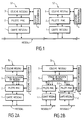
- Figure 1 We first refer to Figure 1 to describe a example of a message transmission installation (or data, or frames) of the prior art.
- the installation forms a local network of the type radio frequency in which messages are exchanged by PC (Personal Computer) computers via the ether medium.
- PC Personal Computer
- each station Si presents a particular communication architecture, organized as follows.
- a so-called communication card 1 is provided network card which includes a transceiver for transmission / reception, a network component capable of recovering messages passing through the medium (here the ether) and store in buffer memory after checking message integrity (or packet, or frame).
- pilot stage 2 (or in English driver) connected to network card 1 by interface means such than an interconnection cable, and allowing the so-called layers "high" network protocols to retrieve messages or packages.
- the pilot stage is of MAC type. But, it could be a pilot stage of another type as for example of type LLC of the ISO model of the OSI.
- this pilot stage 2 is a software layer for initializing communication card 1 (card network) and more particularly its transceiver and network component.
- network layer 3 which is in fact the upper layer of network protocols mentioned above. It is also, in general, of a software layer.
- network layer 3 and MAC pilot stage 2 are connected by interface means, standardized, of the type software.
- interface means standardized, of the type software.
- Windows and Windows NT trademarks registered by MICROSOFT
- NDIS the interface
- ODI ODI
- the network layer (or stage) 3 and the MAC pilot stage 2 are both managed by operating system 4 of the host station in which they are installed. In others terms they operate using the resources of the operating system 4 of station Si.
- the invention therefore provides a particularly solution elegant to the disadvantage presented by the installations of transmission of prior art messages.
- the system operating station 4 of the station Si is chosen to be multitasking.
- the data streams either go upstream, that is to say from the network card 1 to the network layer 3, either in the downward direction, i.e. from the layer network 3 to network card 1.
- the data flows or messages which must be exchanged between network layer 3 and pilot stage 2 are intercepted.
- the MAC 2 pilot stage and the stage network management 3 can, in certain modes of realization, process messages (or frames) which are not intended for the station considered.
- Such a possibility goes, as we will see below, allow the station provide connectivity and / or synchronization functions which go beyond the simple direct transmission of a source station to a final destination station.
- the network management stage 5 may be capable, in certain embodiments, to generate spontaneously, or at the request of a higher level such as by example network layer (or stage) 3, messages, in particular service, to other stations in the network local.
- a higher level such as by example network layer (or stage) 3, messages, in particular service, to other stations in the network local.
- network management stage 5 can perform depend on need. So this management floor of network 5 can only intercept uplink messages or descendants in order to decide on their transmission, with a possible treatment, or allow only to generate descending messages of a chosen type (by example of service or synchronization), or allow both interception and generation of messages.
- FIG. 2B is illustrated a variant of the architecture from the station in Figure 2A.
- the station is connected to two networks (referenced network 1 and network 2).
- Network 1 is here, for example, a wireless network (or radio network) while network 2 is a wired network.
- network 2 is a wired network.
- the two networks could be networks radio transmitting on different frequencies and according to different modes or protocols.
- the network management stage 5 could manage more than two networks, for example three, or four, or more again, with the use of as many layers or stages 2-i drivers and 1-i network communication cards that there has networks.
- the management stage of network 5 of an Si station makes it possible to achieve what humans of art calls a "cable-radio" bridge.
- Such a network management stage 5 is preferably done using software so that it there is no need to change anything nor the network layer (or stage) 3 or the MAC pilot stage 2. Good heard, when we have the source codes of the floor MAC 2 pilot, it is possible to combine in a single stage the network management stage 5 and the MAC pilot stage 2.
- the network management stage 5 is capable of performing at least one function, and preferably at least two. This is particularly the case in the examples illustrated in Figures 3A and 3B. Indeed, the floor of network management 5 is arranged so as to allow the routing (in the broadest sense of the term), as well as the management of messages or service packets.
- Such a message includes at least one field comprising a address pair, including a station address final destination 6 and a source station address initial 7, as well as data 13 forming the content of the message to be processed.
- destination station final 6 the station which is the recipient of the message
- initial source station 7 is the one which transmitted the message to the final destination station 6.
- the frame illustrated in Figure 4 can possibly contain other information. Such information can be found, for example, in the IEEE 802.11 standard.
- the address of the final destination station is directly used by network card 1 to filter the frames which reach it, so that only the frames, except in cases cash, which arrived at destination, and which by therefore concern the host station, have gone back to the network layer 3.
- Figure 5 is illustrated a package (or frame, or still message) of the type that can be used in an installation according to the invention.
- this type of message could include significantly less information or fields, especially in modes called “broadcast” or “full promiscuous” which are modes called “broadcast”.
- a frame of the type illustrated in FIG. 5 includes a first field consisting of a first pair of addresses, including a final destination station address 6 and an initial source station address 7, a second field consisting of a second pair of addresses, forming a capsule (or part of capsule), and including a station address intermediate destination 8 and a source station address intermediate 9, a field 10 designating the type of frame (or in other words the type of information contained in the message or frame), a field designating 11 a number of sequence, possibly other types of information 12, as well as the data 13, forming the content of the message to treat.
- Such a frame is called a frame in the second format, in comparison with a frame which "leaves" network stage 3 said in the first format and which does not include a second pair of addresses.
- the frame is said to be encapsulated.
- intermediate destination station 8 the next station to which a message should be sent, while the intermediate source station 9 is the station who will send the message to the destination station intermediate 8.
- the frame type field 10 will be used to direct the weft that reaches the floor of network management 5, thereby optimizing its processing.
- Sequence number field 11 is not required, but it can be useful insofar as it makes it possible to refuse frames already received or not taking into account some between them.
- the first pair of addresses 6 and 7 will be used in routing / relaying functions, which will be described later, in order to optimize the choice of the intermediate destination station 8.
- the final destination station 6 can be identical to the intermediate destination station 8. From even, when a message is sent by a given host station, the address of the original source station 7, which is its own address, is identical to the address of the source station intermediate 9.
- the network management stage 5 must provide a function message routing, as well as a management function service packets (or messages). To do this, it includes a network service management module 14 as well as a module management of service packets (or messages) 15 connected to a switch module 16 which communicates, on the one hand, with the network layer 3, and on the other hand, with a de-encapsulation / encapsulation module 17, itself “connected" to the floor MAC driver 2.
- this de-encapsulation / encapsulation module 17 is to removing or adding the capsule (or the capsule part) composed in particular of the second pair of addresses 8 and 9, depending on whether the direction of data transmission is increasing or descending.
- the MAC pilot stage 2 When the MAC pilot stage 2 receives from network card 1 a message in the second format, of the type illustrated on the figure 5, it makes it go up towards the network layer 3. From made of the presence of the network management stage 5, the message in the second format is intercepted at the exit of the floor MAC 2 driver before it gets to network layer 3. More precisely, this message in the second format is intercepted by the de-encapsulation / encapsulation module 17 which extracts therefrom the capsule, i.e. the second pair of addresses 8 and 9. Extraction can be physical, i.e.
- the message in the second format can have this second pair removed addresses 8 and 9 (or capsule, or part of capsule), which can possibly be memorized, but it can also be "virtual", the second pair of addresses remaining in the message in the second format (and said message possibly remaining memorized in its entirety in a appropriate memory).
- the message decapsulated by the module de-encapsulation / encapsulation 17 is then transmitted to the referral module 16, which will then analyze field 10 type of frame it contains so as to transmit the unencapsulated message either to one of modules 14 and 15 of network management stage 5, either directly at the layer network 3, again at network layer 3 and at least one modules 14 and 15.
- a message of service received by network management stage 5 is therefore distributed by the referral module 16 to the single service packet management 15.
- a message containing routing information or to be routed will be directly distributed by the referral module to routing module 14.
- a message containing only data 13 (or information) concerning the upper layers of the station will be directly distributed by the referral module 16 at network layer 3.
- Reverse reasoning can be applied for a message descendant from a high layer, such as the layer network 3, and directed to the MAC 2 pilot stage (see figure 7).
- the message that is provided by the layer network 3 is in the first format, insofar as it contains data 13 as well as a first pair of addresses containing a final destination station address 6 and an initial source station address 7 which in this case is happens to be the host station. But this message could understand other fields different from the second pair addresses 8 and 9.
- This message in the first format is, except for exceptions linked to a "broadcast” (or “broadcast”) type of transmission, intercepted by network management stage 5, and more precisely by its referral module 16.
- a message in first format from network layer 3 may contain information useful for one of the modules 14 or 15, or a request to send a message from service.
- the management module of network services 14 (routing) has the function of determining, from the address of the final destination station 6 contained in the first pair of addresses in the message to first format received from network layer 3, the address of the intermediate destination station 8 of the second pair addresses to which the message.
- This referral is made, as in the upward direction, to from the analysis of field 10, i.e. the type of frame or message.
- the management module of network service 14 (routing) delivers to this same routing module 16 an intermediate destination station address 8.
- the module 16 transmits to the de-encapsulation / encapsulation module 17 the message in the first format as well as the address of the intermediate destination station 8.
- the de-encapsulation / encapsulation module 17 then forms a message in the second format (of the type illustrated on the figure 5) by adding to the message the first format from network layer 3 a capsule (or part of a capsule) consisting of the second pair of addresses 8 and 9, which includes the address of the intermediate destination station 8 determined by module 14 as well as the address of the intermediate source station 9, i.e. that of the host station in which it is located.
- This message in the second format is then transmitted to the floor MAC driver 2, then to network card 1 for transmission in the medium, here the ether, towards the station of intermediate destination 8 contained in the capsule (or second pair of message addresses in second format).
- the module of de-encapsulation / encapsulation 17 is capable of receiving messages in the second format of a first MAC 2-1 pilot stage and a second MAC 2-2 pilot stage, as well as providing these two stages, either separately or simultaneously, messages in the second format generated either by one of the modules 14 or 15 of network management stage 5, either by network layer 3.
- processing may be slightly different.
- the service packet management module 15 can, either spontaneously or at the request of a top layer send a service message to one or more stations from one or more networks.
- spontaneously is meant a message sent automatically, for example periodically, or issued when a topological change has occurred place in a routing table of the station concerned continued upon receipt of a service message.
- Such a service message may also be intended for all the stations in the network, for example when includes topological and / or neighborhood information intended for updating station routing tables of the network, and therefore intended to improve their connectivity.
- the service message is made up from a query of the content of a table of routing (or several tables or directories) stored in a memory 15 of the network service management module 14 (routing).
- the module 15 interrogates the network service management 14 so as to determine a intermediate destination station address 8 allowing optimize the routing of said service message by direction of the final destination station 6.
- the message service and the address of the intermediate destination station 8 are then transmitted to the switching module 16 and then to the de-encapsulation / encapsulation module 17.
- an uplink service message reaches the level of the switching module 16, this by detecting by its field 10 (frame type) that it is actually a service message, transmits it to the management module service packets 15, which extracts the information therefrom view of their treatment.
- Two types of service messages can be received or generated by the packet management module of service 15.
- these are the so-called “from neighborhood "which are usually sent in a so-called mode "broadcast at a jump".
- Such neighborhood messages usually include the list of neighbors of the station host. It will be convenient to add in correspondence of each a neighboring station a status chosen from the following list: asymmetrical link, symmetrical link, multipoint relay.
- These neighborhood messages are accompanied by a stamp (contained for example in field 11 giving the number of sequence) allowing to recognize a message carrying more recent information.
- a status of type "asymmetric link” indicates that the station hear another station and not sure if heard by it.
- a status of type "link symmetric” indicates that the station hears another station and is sure to be heard by it.
- a status of type "multipoint relay” is a special status which allows to designate specific stations allowing a given station to provide multipoint transmissions. As the exchanges between message stations of neighborhood, the status of neighboring stations is being refined.
- Topology messages are sent, generally, in a mode called “broadcast”. They include a list of neighbors of the transmitting station (host) which allows to build the complete network topology.
- the topology messages will therefore be sent either in general broadcast mode (approach link state type), or in one-hop broadcast (approach distance vector type).
- Service messages which have been recognized by the module switch 16 as carriers of topological information or neighborhood are provided to the packet management module service 15 (see figure 6). This extracts the information and transmits them to the network service management module 14 (routing), and more precisely to a module for calculating routing tables 18 that it includes.
- the or the routing tables are stored in this calculation module 18, so that upon receipt of the information the calculation means can recalculate (or modify, or supplement) these routing tables (or in others terms update them).
- Calculating a routing table can be considered, in first approximation, like calculating all paths allowing a given host station to reach so optimal the other station (s) in the network (s) to which it is connected.
- the routing tables can be calculated by any method known to those skilled in the art, depending on the type chosen approach. We can notably rely on the calculation of the number of jumps necessary to reach a destination, for example using type algorithms DJISTRA or BELLMAN FORD.
- the module for managing service packets 15 includes a timer able to count down a time period of length predetermined, so that at the end of each period a service message is systematically generated. The countdown defines a message generation criterion which is checked at each end of period detection.
- the service message can be generated by the service packet management module 15 on an order (or request) received from an upper layer, such as the network layer 3 from the host station, or at the request of a configuration 19.
- an upper layer such as the network layer 3 from the host station, or at the request of a configuration 19.
- a message from service may be issued spontaneously when a change topological took place in a station routing table concerned following the receipt of a service message.
- Such a configuration module 19 can be formed, by example of utility software allowing a user computer (or host station) to enter information or choose options, allowing to set the parameters of operation of the various modules, stages and cards of the station.
- the configuration module 19 could also allow a user to enter all information, or only some, making it possible to constitute or modify the different routing tables stored in the network service management module 14 (routing).
- a such a configuration module 19 could make it possible to manage the length of the delay time setting the period time of the service message generation criterion by the service packet management module 15.
- Such a configuration module 19 could allow to visualize on the station monitor the different topological tables, thus allowing, for example, view the links between the different stations of the networks to which the station, in which it is located, is connected.
- FIG. 8 we now refer more particularly to FIG. 8 to describe another mode of operation of an installation according to the invention.
- the network management stage 5 which will decide to the continuation of the transmission of a message received to the second format.
- the network management stage 5 is capable, upon receipt of an uplink message, from the network card 1 via the MAC pilot stage 2, perform a first test 100 relating to the address of the final destination 6 contained in the first pair of addresses of the message received in the second format. If the result of this first test is positive, then the referral module 16 transmits the message (possibly previously unwrapped by the de-encapsulation / encapsulation module 17) at network layer 3, which constitutes step 110.
- the network management stage 5 performs a second test 120 so as to determine whether the message received on the second format must also be retransmitted to one or more other stations in the network (s). If the result of this test 120 is negative, then, the processing carried out by the stage of network management 5 ends. However, if the result of this test 120 is positive or if the result of the first test 100 is negative, then the network service management module 14 (routing), and more precisely its optimization module path 20, in step 130, determines the address of the next relay station to which be retransmitted said message.
- the path optimization module 20 will read the routing table (s) stored in the calculation module 18 to extract a destination station address intermediate 8 and transmit it to the referral module 16 who will then communicate it to the de-encapsulation / encapsulation module 17 together with the message to be retransmitted.
- the message received in the second format remains in the de-encapsulation / encapsulation module 17, for example in an appropriate memory, and that the routing module 16 only transmits to it the address of the intermediate destination station 8.
- the de-encapsulation / encapsulation module 17 no longer has than to replace the second pair of addresses contained in the message received in second format by a new second pair of addresses consisting of the address of the destination station intermediary provided by the module for determining the optimal path 20, as well as the source station address intermediary 9 which is nothing but the address of the host station.
- step 140 which ends the processing procedure by the network management stage 5.
- messages in the second format can include a field (for example 11 or 12) allowing the network card 1 to ignore them, without them coming back up, and therefore avoid the network management stage 5 works unnecessarily.
- FIG. 9 we now refer to FIG. 9 to describe a variant of the embodiments of the management stage of network 5 illustrated in FIGS. 3A and 3B.
- the management stage of network 5 includes a synchronization module 21 allowing to synchronize the host station, and more precisely, to minus its transmission / reception means housed in the card network 1.
- Synchronization here means both frequency synchronization so that you can lock the station on the frequency of transmission of synchronization messages, that time synchronization so as to providing said host station with a common time reference allowing it to effectively lock onto the frequency mode transmission of synchronization messages.
- This synchronization mode is particularly useful in networks of the so-called "frequency hopping” type in which the frequency of transmission of messages varies over time, at the station level, according to a frequency diagram and known time, for example.
- the synchronization module 21 can either be connected to the network card 1 via the MAC pilot stage 2 (as illustrated in Figure 9), either be able to provide this network card 1 with synchronization information via the referral module 16, the de-encapsulation / encapsulation module 17 and the MAC 2 pilot stage.
- the service packet management module 15 has a part 22 dedicated to the management of messages from synchronization. So the generation of service messages, whether they are topological messages, neighborhood or synchronization messages can be managed by a single service packet management module 15.
- part 22 of this management module service dedicated to the synchronization message, is in close relationship with the synchronization module 21 of way to provide it with synchronization information contained in synchronization messages received from switch module 16.
- the synchronization module could include its own service packet management means of synchronization.
- the information relating to the common frequency, contained in synchronization messages may include either the list of frequencies in the frequency development diagram common and the respective lengths of stay of these frequencies, either a frequency and duration list identifier associated, the stations then having a memory in which is stored a correspondence table between list identifiers and lists and durations.
- the invention also allows, thanks to the synchronization module, manage message exchanges between networks operating according to different synchronizations.
- the process may also include all the stages of treatment which have been described previously with reference to installation variants.
- messages in the second format comprising first and second fields each consisting of a first or second pair of addresses.
- a message in the second format has only a second field, this field preferably being made up of the single address of the intermediate station determined by the floor of management.
- messages in the second format have first and second fields, made up the address of the source station, respectively final and the sole address of the intermediate station determined by the management level.
- the second format can present, or approach, respectively selected forms by 802.11 and HIPERLAN standards. he is also conceivable that the aforementioned formats could be used with slight modifications relating to the use of some fields.
- the 802.11 standard contains fields which can carry the address of the bridges between the network radio and a distribution system. These fields could be used to identify intermediate stations.
- the 802.11 standard offers the possibility of distinguishing between different types of frames; this possibility could be used in the invention to discern the different service frames (or messages).
Landscapes
- Engineering & Computer Science (AREA)
- Computer Networks & Wireless Communication (AREA)
- Signal Processing (AREA)
- Computer Security & Cryptography (AREA)
- Data Exchanges In Wide-Area Networks (AREA)
- Radar Systems Or Details Thereof (AREA)
Applications Claiming Priority (2)
| Application Number | Priority Date | Filing Date | Title |
|---|---|---|---|
| FR9806244 | 1998-05-18 | ||
| FR9806244A FR2778809B1 (fr) | 1998-05-18 | 1998-05-18 | Installation de transmission de messages a stations perfectionnees, et procede correspondant |
Publications (2)
| Publication Number | Publication Date |
|---|---|
| EP0959602A1 true EP0959602A1 (de) | 1999-11-24 |
| EP0959602B1 EP0959602B1 (de) | 2006-02-15 |
Family
ID=9526453
Family Applications (1)
| Application Number | Title | Priority Date | Filing Date |
|---|---|---|---|
| EP99401160A Expired - Lifetime EP0959602B1 (de) | 1998-05-18 | 1999-05-11 | Anordnung für Nachrichtübertragung mit verbesserten Stationen und entsprechendes Verfahren |
Country Status (4)
| Country | Link |
|---|---|
| US (1) | US6697379B1 (de) |
| EP (1) | EP0959602B1 (de) |
| DE (1) | DE69929868T2 (de) |
| FR (1) | FR2778809B1 (de) |
Cited By (2)
| Publication number | Priority date | Publication date | Assignee | Title |
|---|---|---|---|---|
| WO2003030461A1 (en) * | 2001-09-28 | 2003-04-10 | Intel Corporation | Method, apparatus and computer program for the decapsulation and encapsulation of packets with multiple headers |
| US9824038B2 (en) | 1999-12-27 | 2017-11-21 | Intel Corporation | Memory mapping in a processor having multiple programmable units |
Families Citing this family (42)
| Publication number | Priority date | Publication date | Assignee | Title |
|---|---|---|---|---|
| US6983350B1 (en) | 1999-08-31 | 2006-01-03 | Intel Corporation | SDRAM controller for parallel processor architecture |
| US6532509B1 (en) | 1999-12-22 | 2003-03-11 | Intel Corporation | Arbitrating command requests in a parallel multi-threaded processing system |
| US7620702B1 (en) | 1999-12-28 | 2009-11-17 | Intel Corporation | Providing real-time control data for a network processor |
| US6661794B1 (en) | 1999-12-29 | 2003-12-09 | Intel Corporation | Method and apparatus for gigabit packet assignment for multithreaded packet processing |
| US6584522B1 (en) | 1999-12-30 | 2003-06-24 | Intel Corporation | Communication between processors |
| US7480706B1 (en) | 1999-12-30 | 2009-01-20 | Intel Corporation | Multi-threaded round-robin receive for fast network port |
| US6952824B1 (en) | 1999-12-30 | 2005-10-04 | Intel Corporation | Multi-threaded sequenced receive for fast network port stream of packets |
| US7159233B2 (en) * | 2000-01-28 | 2007-01-02 | Sedna Patent Services, Llc | Method and apparatus for preprocessing and postprocessing content in an interactive information distribution system |
| US7152103B1 (en) * | 2001-01-10 | 2006-12-19 | Nortel Networks Limited | Lawful communication interception—intercepting communication associated information |
| US7197045B2 (en) * | 2001-01-16 | 2007-03-27 | Texas Instruments Incorporated | CMTS architecture based on ethernet interface locatable in a fiber node |
| US20020159468A1 (en) * | 2001-04-27 | 2002-10-31 | Foster Michael S. | Method and system for administrative ports in a routing device |
| US7471688B2 (en) | 2002-06-18 | 2008-12-30 | Intel Corporation | Scheduling system for transmission of cells to ATM virtual circuits and DSL ports |
| US7352769B2 (en) | 2002-09-12 | 2008-04-01 | Intel Corporation | Multiple calendar schedule reservation structure and method |
| US7433307B2 (en) | 2002-11-05 | 2008-10-07 | Intel Corporation | Flow control in a network environment |
| US7443836B2 (en) | 2003-06-16 | 2008-10-28 | Intel Corporation | Processing a data packet |
| US8422667B2 (en) | 2005-01-27 | 2013-04-16 | The Chamberlain Group, Inc. | Method and apparatus to facilitate transmission of an encrypted rolling code |
| US9148409B2 (en) | 2005-06-30 | 2015-09-29 | The Chamberlain Group, Inc. | Method and apparatus to facilitate message transmission and reception using different transmission characteristics |
| US12556387B2 (en) | 2005-01-27 | 2026-02-17 | The Chamberlain Group Llc | Method and apparatus to facilitate transmission of an encrypted rolling code |
| USRE48433E1 (en) | 2005-01-27 | 2021-02-09 | The Chamberlain Group, Inc. | Method and apparatus to facilitate transmission of an encrypted rolling code |
| US20060200711A1 (en) * | 2005-02-01 | 2006-09-07 | Schondelmayer Adam H | Network diagnostic systems and methods for processing network messages |
| WO2006083959A2 (en) * | 2005-02-01 | 2006-08-10 | Finisar Corporation | Network diagnostic system and methods for aggregated links |
| US20060198318A1 (en) * | 2005-02-01 | 2006-09-07 | Schondelmayer Adam H | Network diagnostic systems and methods for statistical triggering |
| US20060198312A1 (en) * | 2005-02-01 | 2006-09-07 | Schondelmayer Adam H | Network diagnostic systems and methods for altering the format and bandwidth of network messages |
| US20070211697A1 (en) * | 2006-03-13 | 2007-09-13 | Finisar Corporation | Method of analyzing network with generated traffic |
| US8107822B2 (en) | 2005-05-20 | 2012-01-31 | Finisar Corporation | Protocols for out-of-band communication |
| US20070038880A1 (en) * | 2005-08-15 | 2007-02-15 | Noble Gayle L | Network diagnostic systems and methods for accessing storage devices |
| US20060264178A1 (en) * | 2005-05-20 | 2006-11-23 | Noble Gayle L | Wireless diagnostic systems |
| US20080075103A1 (en) * | 2005-05-20 | 2008-03-27 | Finisar Corporation | Diagnostic device |
| US7899057B2 (en) * | 2006-04-28 | 2011-03-01 | Jds Uniphase Corporation | Systems for ordering network packets |
| US20070211696A1 (en) * | 2006-03-13 | 2007-09-13 | Finisar Corporation | Method of generating network traffic |
| US20070260728A1 (en) * | 2006-05-08 | 2007-11-08 | Finisar Corporation | Systems and methods for generating network diagnostic statistics |
| US8213333B2 (en) | 2006-07-12 | 2012-07-03 | Chip Greel | Identifying and resolving problems in wireless device configurations |
| US8526821B2 (en) * | 2006-12-29 | 2013-09-03 | Finisar Corporation | Transceivers for testing networks and adapting to device changes |
| US8175101B2 (en) * | 2008-08-15 | 2012-05-08 | Raytheon Company | Multicasting in a network using neighbor information |
| EP2401826A2 (de) * | 2009-02-25 | 2012-01-04 | Spidercloud Wireless, Inc. | System und verfahren zur organisation eines netzwerks |
| US20100265955A1 (en) * | 2009-04-17 | 2010-10-21 | Park Sung I | Cross layer routing (xrp) protocol |
| US9565132B2 (en) | 2011-12-27 | 2017-02-07 | Intel Corporation | Multi-protocol I/O interconnect including a switching fabric |
| GB2516837B (en) | 2013-07-31 | 2015-12-09 | Ip Access Ltd | Network elements, wireless communication system and methods therefor |
| US10652743B2 (en) | 2017-12-21 | 2020-05-12 | The Chamberlain Group, Inc. | Security system for a moveable barrier operator |
| US11074773B1 (en) | 2018-06-27 | 2021-07-27 | The Chamberlain Group, Inc. | Network-based control of movable barrier operators for autonomous vehicles |
| US11423717B2 (en) | 2018-08-01 | 2022-08-23 | The Chamberlain Group Llc | Movable barrier operator and transmitter pairing over a network |
| US10997810B2 (en) | 2019-05-16 | 2021-05-04 | The Chamberlain Group, Inc. | In-vehicle transmitter training |
Citations (4)
| Publication number | Priority date | Publication date | Assignee | Title |
|---|---|---|---|---|
| US5412654A (en) * | 1994-01-10 | 1995-05-02 | International Business Machines Corporation | Highly dynamic destination-sequenced destination vector routing for mobile computers |
| WO1997001940A1 (en) * | 1995-06-27 | 1997-01-16 | Philips Electronics N.V. | Network interconnecting system |
| EP0767564A2 (de) * | 1995-10-06 | 1997-04-09 | Canon Kabushiki Kaisha | Protokollrekonfigurierung in einem Netzschnittstellengerät |
| EP0838930A2 (de) * | 1996-10-25 | 1998-04-29 | Digital Equipment Corporation | Pseudonetzwerkadapter zur Rahmenaufnahme, -einkapselung und -verschlüsselung |
Family Cites Families (6)
| Publication number | Priority date | Publication date | Assignee | Title |
|---|---|---|---|---|
| FR838930A (fr) | 1937-07-24 | 1939-03-20 | Felten & Guilleaume Carlswerk | Conducteur électrique avec isolant en filés ou soie de verre |
| US6188689B1 (en) * | 1996-10-04 | 2001-02-13 | Kabushiki Kaisha Toshiba | Network node and method of frame transfer |
| US6160795A (en) * | 1997-03-21 | 2000-12-12 | Siemens Aktiengesellschaft | Network communication |
| EP0871309B1 (de) * | 1997-04-07 | 2005-10-19 | Kabushiki Kaisha Toshiba | Wegesuchvorrichtung und Rahmenübertragungsverfahren unter Verwendung von Rahmenvermittlung auf Datenverbindungsschicht |
| JP3042457B2 (ja) * | 1997-08-21 | 2000-05-15 | 日本電気株式会社 | マルチレイヤatm通信装置 |
| JP3490286B2 (ja) * | 1998-03-13 | 2004-01-26 | 株式会社東芝 | ルータ装置及びフレーム転送方法 |
-
1998
- 1998-05-18 FR FR9806244A patent/FR2778809B1/fr not_active Expired - Fee Related
-
1999
- 1999-05-11 EP EP99401160A patent/EP0959602B1/de not_active Expired - Lifetime
- 1999-05-11 DE DE69929868T patent/DE69929868T2/de not_active Expired - Lifetime
- 1999-05-17 US US09/312,486 patent/US6697379B1/en not_active Expired - Lifetime
Patent Citations (4)
| Publication number | Priority date | Publication date | Assignee | Title |
|---|---|---|---|---|
| US5412654A (en) * | 1994-01-10 | 1995-05-02 | International Business Machines Corporation | Highly dynamic destination-sequenced destination vector routing for mobile computers |
| WO1997001940A1 (en) * | 1995-06-27 | 1997-01-16 | Philips Electronics N.V. | Network interconnecting system |
| EP0767564A2 (de) * | 1995-10-06 | 1997-04-09 | Canon Kabushiki Kaisha | Protokollrekonfigurierung in einem Netzschnittstellengerät |
| EP0838930A2 (de) * | 1996-10-25 | 1998-04-29 | Digital Equipment Corporation | Pseudonetzwerkadapter zur Rahmenaufnahme, -einkapselung und -verschlüsselung |
Cited By (6)
| Publication number | Priority date | Publication date | Assignee | Title |
|---|---|---|---|---|
| US9824038B2 (en) | 1999-12-27 | 2017-11-21 | Intel Corporation | Memory mapping in a processor having multiple programmable units |
| US9824037B2 (en) | 1999-12-27 | 2017-11-21 | Intel Corporation | Memory mapping in a processor having multiple programmable units |
| US9830284B2 (en) | 1999-12-27 | 2017-11-28 | Intel Corporation | Memory mapping in a processor having multiple programmable units |
| US9830285B2 (en) | 1999-12-27 | 2017-11-28 | Intel Corporation | Memory mapping in a processor having multiple programmable units |
| WO2003030461A1 (en) * | 2001-09-28 | 2003-04-10 | Intel Corporation | Method, apparatus and computer program for the decapsulation and encapsulation of packets with multiple headers |
| US7126952B2 (en) | 2001-09-28 | 2006-10-24 | Intel Corporation | Multiprotocol decapsulation/encapsulation control structure and packet protocol conversion method |
Also Published As
| Publication number | Publication date |
|---|---|
| DE69929868T2 (de) | 2006-07-20 |
| EP0959602B1 (de) | 2006-02-15 |
| FR2778809B1 (fr) | 2000-07-28 |
| FR2778809A1 (fr) | 1999-11-19 |
| US6697379B1 (en) | 2004-02-24 |
| DE69929868D1 (de) | 2006-04-20 |
Similar Documents
| Publication | Publication Date | Title |
|---|---|---|
| EP0959602B1 (de) | Anordnung für Nachrichtübertragung mit verbesserten Stationen und entsprechendes Verfahren | |
| EP0924898B1 (de) | Vorrichtung und Verfahren zur Verbindung zwischen Netzsegmenten, die mit verschiedenen Protokollformaten kommunizieren | |
| EP1507384B1 (de) | Verfahren zum Ausblenden einer Weiterverarbeitung von einer Zugriffsanforderung zu einem Server und entsprechende Vorrichtung | |
| EP0721271B1 (de) | Zugriffskontrollsystem für an einem Privatnetz angeschlossene Computer | |
| EP1835411B1 (de) | Einchipsystem mit halbverteilter Kontrolle | |
| CA2234306C (fr) | Systeme de liaisons de donnees entre un aeronef et le sol et procede de survie a une panne | |
| EP2954648B1 (de) | Datenroutingverfahren, computerprogramm, netzwerksteuerung und dazugehörige netzwerke | |
| EP3675435A1 (de) | Dynamisches routingverfahren in einem netzwerk von verbundenen objekten | |
| EP1982480B1 (de) | Verfahren zur dynamischen zuteilung der ressourcen in einer netzgruppe | |
| EP0557210B1 (de) | OSI-Transportrelaianordnung zwischen Netzen in verbundener und unverbundener Betriebsart | |
| EP3555745B1 (de) | Vorrichtung zum laden von daten in computerverarbeitungseinheiten aus einer datenquelle | |
| EP1605631B1 (de) | System und Verfahren zum Testen eines Routers | |
| WO2001006702A1 (fr) | Procede de realisation d'une transaction electronique utilisant plusieurs signatures | |
| FR2717334A1 (fr) | Vérification d'intégrité de données échangées entre deux stations de réseau de télécommunications. | |
| EP3373558B1 (de) | Kommunikationsverfahren zur sicherstellung der aufrechterhaltung einer anwendungssession zwischen einem endgerät und einem anwendungsserver | |
| WO2023111432A1 (fr) | Mécanismes de communication avec un service accessible via un réseau de télécommunication prenant en compte la mobilité des services, des utilisateurs et des équipements | |
| EP3747238B1 (de) | Aggregation mehrerer funkverbindungen in einem drahtlosen netzwerk | |
| EP1652346B1 (de) | Verfahren zum finden von mobilen kommunizierenden objekten in einem kommunikationsnetz | |
| EP3675561A1 (de) | Dynamisches routing-verfahren in verbundenen netzen von verbundenen objekten | |
| EP2710820B1 (de) | Kommunikationssystem und entsprechendes verfahren, computerprogramm und speichervorrichtung | |
| FR3093833A1 (fr) | Procédé d’optimisation d’échanges de données dans une infrastructure d’objets connectés | |
| FR2831746A1 (fr) | Procede, systeme et commutateur pour associer un serveur auxiliaire d'un reseau d'acheminement de contenus a un equipement d'un reseau informatique | |
| FR3034604A1 (fr) | Procede de protection d'un reseau de communication, dispositif, equipement de controle et programme d'ordinateur associes | |
| EP0471633A1 (de) | Kommunikationsnetz mit Schreib- und Lesering, und Zugriffs- und Rekonfigurationsverfahren eines solchen Netzes | |
| WO2023275490A1 (fr) | Procede de traitement d'une connexion entre un equipement utilisateur et un equipement distant dans un reseau de communication, procede de controle, dispositifs, satellite, station terrestre, systeme et programmes d'ordinateur correspondants |
Legal Events
| Date | Code | Title | Description |
|---|---|---|---|
| PUAI | Public reference made under article 153(3) epc to a published international application that has entered the european phase |
Free format text: ORIGINAL CODE: 0009012 |
|
| AK | Designated contracting states |
Kind code of ref document: A1 Designated state(s): DE GB IT NL SE |
|
| AX | Request for extension of the european patent |
Free format text: AL;LT;LV;MK;RO;SI |
|
| 17P | Request for examination filed |
Effective date: 20000503 |
|
| AKX | Designation fees paid |
Free format text: DE GB IT NL SE |
|
| 17Q | First examination report despatched |
Effective date: 20041208 |
|
| GRAP | Despatch of communication of intention to grant a patent |
Free format text: ORIGINAL CODE: EPIDOSNIGR1 |
|
| GRAS | Grant fee paid |
Free format text: ORIGINAL CODE: EPIDOSNIGR3 |
|
| GRAA | (expected) grant |
Free format text: ORIGINAL CODE: 0009210 |
|
| AK | Designated contracting states |
Kind code of ref document: B1 Designated state(s): DE GB IT NL SE |
|
| REG | Reference to a national code |
Ref country code: GB Ref legal event code: FG4D Free format text: NOT ENGLISH |
|
| REF | Corresponds to: |
Ref document number: 69929868 Country of ref document: DE Date of ref document: 20060420 Kind code of ref document: P |
|
| GBT | Gb: translation of ep patent filed (gb section 77(6)(a)/1977) |
Effective date: 20060502 |
|
| REG | Reference to a national code |
Ref country code: SE Ref legal event code: TRGR |
|
| PLBE | No opposition filed within time limit |
Free format text: ORIGINAL CODE: 0009261 |
|
| STAA | Information on the status of an ep patent application or granted ep patent |
Free format text: STATUS: NO OPPOSITION FILED WITHIN TIME LIMIT |
|
| 26N | No opposition filed |
Effective date: 20061116 |
|
| PGFP | Annual fee paid to national office [announced via postgrant information from national office to epo] |
Ref country code: NL Payment date: 20090529 Year of fee payment: 11 |
|
| PGFP | Annual fee paid to national office [announced via postgrant information from national office to epo] |
Ref country code: SE Payment date: 20090525 Year of fee payment: 11 Ref country code: IT Payment date: 20090527 Year of fee payment: 11 |
|
| REG | Reference to a national code |
Ref country code: NL Ref legal event code: V1 Effective date: 20101201 |
|
| EUG | Se: european patent has lapsed | ||
| PG25 | Lapsed in a contracting state [announced via postgrant information from national office to epo] |
Ref country code: IT Free format text: LAPSE BECAUSE OF NON-PAYMENT OF DUE FEES Effective date: 20100511 Ref country code: NL Free format text: LAPSE BECAUSE OF NON-PAYMENT OF DUE FEES Effective date: 20101201 Ref country code: SE Free format text: LAPSE BECAUSE OF NON-PAYMENT OF DUE FEES Effective date: 20100512 |
|
| REG | Reference to a national code |
Ref country code: DE Ref legal event code: R082 Ref document number: 69929868 Country of ref document: DE Representative=s name: VOSSIUS & PARTNER PATENTANWAELTE RECHTSANWAELT, DE Effective date: 20120301 Ref country code: DE Ref legal event code: R081 Ref document number: 69929868 Country of ref document: DE Owner name: CONVERSANT INTELLECTUAL PROPERTY MANAGEMENT IN, CA Free format text: FORMER OWNER: INRIA INSTITUT NATIONAL DE RECHERCHE EN INFORMATIQUE ET EN AUTOMATIQUE, LE CHESNAY, FR Effective date: 20120301 |
|
| REG | Reference to a national code |
Ref country code: GB Ref legal event code: 732E Free format text: REGISTERED BETWEEN 20120412 AND 20120418 |
|
| REG | Reference to a national code |
Ref country code: DE Ref legal event code: R082 Ref document number: 69929868 Country of ref document: DE Representative=s name: VOSSIUS & PARTNER PATENTANWAELTE RECHTSANWAELT, DE |
|
| REG | Reference to a national code |
Ref country code: DE Ref legal event code: R082 Ref document number: 69929868 Country of ref document: DE Representative=s name: VOSSIUS & PARTNER PATENTANWAELTE RECHTSANWAELT, DE Effective date: 20141120 Ref country code: DE Ref legal event code: R081 Ref document number: 69929868 Country of ref document: DE Owner name: CONVERSANT INTELLECTUAL PROPERTY MANAGEMENT IN, CA Free format text: FORMER OWNER: MOSAID TECHNOLOGIES INCORPORATED, OTTAWA, ONTARIO, CA Effective date: 20141120 |
|
| PGFP | Annual fee paid to national office [announced via postgrant information from national office to epo] |
Ref country code: GB Payment date: 20150527 Year of fee payment: 17 |
|
| GBPC | Gb: european patent ceased through non-payment of renewal fee |
Effective date: 20160511 |
|
| PG25 | Lapsed in a contracting state [announced via postgrant information from national office to epo] |
Ref country code: GB Free format text: LAPSE BECAUSE OF NON-PAYMENT OF DUE FEES Effective date: 20160511 |
|
| PGFP | Annual fee paid to national office [announced via postgrant information from national office to epo] |
Ref country code: DE Payment date: 20180502 Year of fee payment: 20 |
|
| REG | Reference to a national code |
Ref country code: DE Ref legal event code: R071 Ref document number: 69929868 Country of ref document: DE |