EP3555745B1 - Vorrichtung zum laden von daten in computerverarbeitungseinheiten aus einer datenquelle - Google Patents
Vorrichtung zum laden von daten in computerverarbeitungseinheiten aus einer datenquelle Download PDFInfo
- Publication number
- EP3555745B1 EP3555745B1 EP17826496.6A EP17826496A EP3555745B1 EP 3555745 B1 EP3555745 B1 EP 3555745B1 EP 17826496 A EP17826496 A EP 17826496A EP 3555745 B1 EP3555745 B1 EP 3555745B1
- Authority
- EP
- European Patent Office
- Prior art keywords
- control unit
- connector
- remote control
- connectors
- computer
- Prior art date
- Legal status (The legal status is an assumption and is not a legal conclusion. Google has not performed a legal analysis and makes no representation as to the accuracy of the status listed.)
- Active
Links
Images


Classifications
-
- G—PHYSICS
- G06—COMPUTING OR CALCULATING; COUNTING
- G06F—ELECTRIC DIGITAL DATA PROCESSING
- G06F13/00—Interconnection of, or transfer of information or other signals between, memories, input/output devices or central processing units
- G06F13/38—Information transfer, e.g. on bus
- G06F13/40—Bus structure
- G06F13/4004—Coupling between buses
- G06F13/4022—Coupling between buses using switching circuits, e.g. switching matrix, connection or expansion network
-
- H—ELECTRICITY
- H04—ELECTRIC COMMUNICATION TECHNIQUE
- H04L—TRANSMISSION OF DIGITAL INFORMATION, e.g. TELEGRAPHIC COMMUNICATION
- H04L67/00—Network arrangements or protocols for supporting network services or applications
- H04L67/01—Protocols
- H04L67/04—Protocols specially adapted for terminals or networks with limited capabilities; specially adapted for terminal portability
-
- G—PHYSICS
- G06—COMPUTING OR CALCULATING; COUNTING
- G06F—ELECTRIC DIGITAL DATA PROCESSING
- G06F11/00—Error detection; Error correction; Monitoring
- G06F11/22—Detection or location of defective computer hardware by testing during standby operation or during idle time, e.g. start-up testing
- G06F11/26—Functional testing
-
- G—PHYSICS
- G06—COMPUTING OR CALCULATING; COUNTING
- G06F—ELECTRIC DIGITAL DATA PROCESSING
- G06F13/00—Interconnection of, or transfer of information or other signals between, memories, input/output devices or central processing units
-
- G—PHYSICS
- G06—COMPUTING OR CALCULATING; COUNTING
- G06F—ELECTRIC DIGITAL DATA PROCESSING
- G06F21/00—Security arrangements for protecting computers, components thereof, programs or data against unauthorised activity
- G06F21/70—Protecting specific internal or peripheral components, in which the protection of a component leads to protection of the entire computer
- G06F21/82—Protecting input, output or interconnection devices
-
- G—PHYSICS
- G06—COMPUTING OR CALCULATING; COUNTING
- G06F—ELECTRIC DIGITAL DATA PROCESSING
- G06F8/00—Arrangements for software engineering
- G06F8/60—Software deployment
-
- G—PHYSICS
- G06—COMPUTING OR CALCULATING; COUNTING
- G06F—ELECTRIC DIGITAL DATA PROCESSING
- G06F8/00—Arrangements for software engineering
- G06F8/60—Software deployment
- G06F8/61—Installation
-
- G—PHYSICS
- G06—COMPUTING OR CALCULATING; COUNTING
- G06F—ELECTRIC DIGITAL DATA PROCESSING
- G06F8/00—Arrangements for software engineering
- G06F8/60—Software deployment
- G06F8/65—Updates
-
- H—ELECTRICITY
- H04—ELECTRIC COMMUNICATION TECHNIQUE
- H04L—TRANSMISSION OF DIGITAL INFORMATION, e.g. TELEGRAPHIC COMMUNICATION
- H04L12/00—Data switching networks
- H04L12/02—Details
- H04L12/12—Arrangements for remote connection or disconnection of substations or of equipment thereof
-
- H—ELECTRICITY
- H04—ELECTRIC COMMUNICATION TECHNIQUE
- H04L—TRANSMISSION OF DIGITAL INFORMATION, e.g. TELEGRAPHIC COMMUNICATION
- H04L41/00—Arrangements for maintenance, administration or management of data switching networks, e.g. of packet switching networks
- H04L41/08—Configuration management of networks or network elements
- H04L41/0803—Configuration setting
- H04L41/0813—Configuration setting characterised by the conditions triggering a change of settings
- H04L41/082—Configuration setting characterised by the conditions triggering a change of settings the condition being updates or upgrades of network functionality
-
- H—ELECTRICITY
- H04—ELECTRIC COMMUNICATION TECHNIQUE
- H04L—TRANSMISSION OF DIGITAL INFORMATION, e.g. TELEGRAPHIC COMMUNICATION
- H04L49/00—Packet switching elements
- H04L49/25—Routing or path finding in a switch fabric
- H04L49/253—Routing or path finding in a switch fabric using establishment or release of connections between ports
-
- H—ELECTRICITY
- H04—ELECTRIC COMMUNICATION TECHNIQUE
- H04L—TRANSMISSION OF DIGITAL INFORMATION, e.g. TELEGRAPHIC COMMUNICATION
- H04L67/00—Network arrangements or protocols for supporting network services or applications
- H04L67/01—Protocols
- H04L67/06—Protocols specially adapted for file transfer, e.g. file transfer protocol [FTP]
-
- H—ELECTRICITY
- H04—ELECTRIC COMMUNICATION TECHNIQUE
- H04L—TRANSMISSION OF DIGITAL INFORMATION, e.g. TELEGRAPHIC COMMUNICATION
- H04L67/00—Network arrangements or protocols for supporting network services or applications
- H04L67/01—Protocols
- H04L67/12—Protocols specially adapted for proprietary or special-purpose networking environments, e.g. medical networks, sensor networks, networks in vehicles or remote metering networks
-
- H—ELECTRICITY
- H04—ELECTRIC COMMUNICATION TECHNIQUE
- H04L—TRANSMISSION OF DIGITAL INFORMATION, e.g. TELEGRAPHIC COMMUNICATION
- H04L67/00—Network arrangements or protocols for supporting network services or applications
- H04L67/34—Network arrangements or protocols for supporting network services or applications involving the movement of software or configuration parameters
Definitions
- the present invention relates to the loading of data into computer units.
- Such a computer unit comprises at least one memory and one processor for processing data so as to form, for example, a computer.
- the data is loaded into the computer units, for example to update the programs contained in the computer units or to update the data used by the computer units for carrying out the processing entrusted to them.
- the update data is generally contained in a data source usually formed of a computer running data loading software.
- the data source can also be a portable memory medium such as a memory card.
- an Ethernet switch inspects the data packets passing through it to read the MAC address of the recipient so that a fraudster who has access to a computer unit on the network and who knows the MAC address of a another of the computer units in the network could send messages directly to this last unit.
- the only known solution resides in the implementation of a particular protocol or device which would prohibit some of the computer units from communicating with each other, nevertheless the existence of a permanent physical link between the computer units leaves a risk of circumvention of the protocol.
- the document US-A-2009/303883 describes a data routing method implementing an Ethernet protocol and using MAC addresses to route the data.
- the document US-A-2014/321477 describes a device for selectively connecting at least one first piece of computer equipment to a plurality of second pieces of computer equipment.
- An object of the invention is to make the transfer of data more reliable.
- the data source would then be connected to the first connector and the computer units to the second connectors.
- the association of each connector with a PHY component makes it possible to identify this connector, and therefore the computer unit which is connected to it, by means of the identifier which is assigned to each PHY component.
- the local control unit makes it possible to select the second connector, and therefore the computer unit, to be connected to the first connector, and therefore to the data source.
- the data loading device does not have to know the MAC address of the recipient, the selection of the recipient being able to be made from the identification of the PHY components of each connector. It is therefore not necessary to decode the data and then recode them to route them: the data is copied as is from one PHY component to another.
- the PHY components therefore make it possible to connect each of the computer units connected to the second connectors to the data source connected to the first connector and, in combination with the selection modules, prevent any direct connection between the computer units. Indeed, by connecting to one of the second connectors, it is impossible to access a computer unit which would be connected to another of the second connectors since there is no physical link between them.
- the device comprises a chassis on which are mounted the selection modules, the first connector, and the second connectors; the control unit comprising a local control unit and a remote control unit connected by a cable to the local control unit and provided with a man-machine interface.
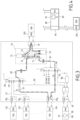
- the data loading device is described here in relation to the updating of computer units 100 of an aircraft, and more particularly here an airliner.
- the computer units 100 include in particular computers involved in the operation of the aircraft, for example flight and navigation computers, and computer units dedicated to the entertainment of the passengers of the aircraft, and for example video servers at the asked.
- the update data include, for example, a new version of a program, a corrective "patch", updated values of parameters, etc.
- the computer units 100 are N in number (only three being visible in the figures) and are denoted 100 i to distinguish them from each other with i varying from 1 to N.
- Each computer unit 100 i conventionally comprises at least one memory and one processor for executing a program contained in the memory with a view to processing data stored in the memory and/or data originating from components, such as sensors, connected to the computer unit.
- Each computer unit 100 i comprises in known manner a connector 101 provided with a PHY component. It is recalled that the PHY component is an analog-digital conversion cell constituting the physical layer of the OSI model.
- the update data of the computer units 100 i are stored in a data source here formed by a computer unit 200 which conventionally comprises at least one memory containing the update data, and a processor for executing a program for loading of data contained in the memory in order to allow the loading of the update data into the computer units 100 i for which said update data are intended.
- the computer unit 200 comprises in a manner known per se a connector provided with a component 201 PHY.
- the functions of the computer unit 200 are similar to those of the PSL of traditional aircraft computer update systems.
- Computer units 100 i are connected to computer unit 200 via a data loading device according to the invention.
- the functions of the data loading device are similar to those of the DLRB of traditional aircraft computer update systems.
- the selection module 40 has an input connected to a first RMII bus 61 and N+2 outputs noted from 0 to N and X.
- the outputs 1 to N are each connected to the PHY component of one of the second connectors 20 i by a line 41; output 0 is not connected; and the output X is connected to the PHY component of the third connector 30 by a line 42.
- the selection module 50 has an output connected to a second RMII bus 62 and N+2 inputs noted from 0 to N and X.
- the inputs 1 to N are each connected to the PHY component of one of the second connectors 20 i by a line 51; input 0 is not connected; and the input X is connected to the PHY component of the third connector 30 by a line 52.
- the selection module 40 is arranged to define a single downlink so as to transmit data from the first connector 10 to each of the second connectors 20i alternately, and the selection module 50 is arranged to define a single uplink so as to transmit data in reverse.
- the selection modules 40, 50 are arranged to be able to connect simultaneously to the first connector 10 only one of the second connectors 20 i .
- Lines 41 are distinct from lines 51; and line 42 is separate from line 52.
- the RMII buses 61 and 62 are distinct from each other and are connected to a test module generally designated at 70. More specifically, the first RMII bus 61 is connected to the output of a multiplexer 71 having a first input connected to the first connector 10 and a second input connected to a signal generator 72. The second RMII bus 62 is connected to an input of a demultiplexer 73 having a first output connected to a signal analyzer 74 and a second output connected to a first input of a multiplexer 75 having a second input connected to the signal generator 72 and an output connected to the first connector 10. The first connector 10 is also connected by its downward channel to the signal analyzer 74.
- the selection modules 40, 50 and the RMII buses 61, 62 are formed on an FPGA circuit.
- the selection modules 40, 50 have a control input connected to a control output of a local control unit 80 arranged to control the selection modules 40, 50 with a view to selecting the second connector 20 i to be connected to the first connector 10.
- Selection modules 40, 50; buses 61, 62; the test module 70; the first connector 10; the second connectors 20 i ; the third connector 30 and the local control unit are here mounted on a common chassis.
- the device further comprises a remote control unit 90 which conventionally comprises at least one memory and a processor for executing a program contained in the memory in order to allow an operator to choose the computer units 100 i that he wants to put up to date.
- the memory contains a table linking an identifier and a transfer speed of the computer unit 100 i with the second connector 20 i to which the computer unit 100 i is connected.
- the remote control unit 90 is provided with a man-machine interface, here a screen 91 and a button 92 for selecting options displayed on the screen 91.
- the functions of the remote control unit 90 are similar to those of the DSLU of traditional aircraft computer update systems.
- the remote control unit 90 is connected by a cable to the third connector 30 and therefore to the local control unit 80.
- the remote control unit 90 and the local control unit 80 are programmed to communicate with each other by means of IP and UDP protocols, the remote control unit 90 and the local control unit 80 having static IP and MAC addresses.
- the remote control unit 90 and the local control unit 80 are programmed to respectively form a master unit and a slave unit.
- the remote control unit and the local control unit are arranged in such a way that the local control unit cannot be supplied with energy when the remote control unit is not supplied with power.
- the remote control unit 90 When the remote control unit 90 is powered up by the operator, the remote control unit 90 checks that the aircraft is stationary and, if necessary, controls the power supply to the local control unit. command 80 and load the table there. The remote control unit 90 then displays a menu offering the update of the computer units 100 i and a choice of the computer unit 100 i to be updated. By means of the button 92, the operator chooses for example to update the computer unit 100 2 and connects to the first connector 10 a computer unit 200.
- the remote control unit 90 then sends to the local control unit 80 an instruction for linking the computer unit 200 to the computer unit 100 2 .
- the local control unit 80 returns an acknowledgment to the remote control unit 90 and controls the selection modules 40 and 50 to connect the PHY component of the first connector 10 to the PHY component of the second connector 20 2 in accordance with what appears in the table it has in memory.
- the transfer speed is fixed to the value listed in the table or, if the computer unit 100 2 can not communicate at this transfer speed, a negotiation is initiated to determine a lower transfer speed.
- the remote control unit 90 can also be placed in communication with the computer unit 200 if it sends the corresponding instruction to the local control unit 80.
- An uplink and a downlink are established between the PHY components of the first connector 10 and the second connector 20 2 at the stored transfer rate or at the auto-negotiated rate.
- the computer unit 200 program then controls the transmission of the update data.
- the operator indicates to the remote control unit 90, by means of the man-machine interface, either to stop the update, or the choice of a new computer unit 100 i .
- the loading device does not have to inspect the messages in order to route them.
- the remote control unit 90 comprises a box provided with a connector 93 connected directly to the first connector 10 of the charging device 1.
- the computer unit 200 is no longer connected directly to the first connector 10 but is connected to the connector 93 so that the computer unit 200 is connected to the first connector 10 via the connector 93 of the remote control unit 90.
- a device is advantageously provided making it possible to ensure that several PHY components of the second connectors cannot be in their activation state simultaneously.
- the local control unit 80 is arranged to detect the state of the PHY components of the second connectors 20 i and only authorize the activation of one of these when the PHY components of the other second connectors connectors 20 i are in their inactivation state.
- the local control unit 80 is arranged to detect the state of the PHY components of the second connectors 20 i and to deactivate all the active PHY components of the second connectors 20 i if several of these are detected in their activation state.
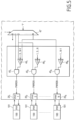
- each second connector 20 i is activated by a signal PWREN coming from an ET cell 45 i whose first input is connected to an output of a device 47 (said output corresponding to the second connector 20 i in question) and a second input is connected to an OR cell 46 i (or NOR) having inputs connected to the outputs of the unit 47 (said outputs corresponding to other second connectors 20 i than the second connector 20 i in question).
- Unit 47 also has an input at 1 and a selection input i.
- a PHY component of a second connector 20 i can only be in its activated state if no other of the second connectors has its PHY component activated.
- the charging device may or may not include the additional safety function of rendering the PHY components inactive when two PHY components are simultaneously detected in their active state.
- the control unit may or may not be arranged to detect the state of the PHY components of the second connectors and to issue an alert if it detects that two PHY components of the second connectors are simultaneously active. This alert can example lead to the inactivation of at least one or both of said PHY components, the storage of a fault in a fault log, the stopping of loading operations while awaiting human intervention ...
Landscapes
- Engineering & Computer Science (AREA)
- Theoretical Computer Science (AREA)
- General Engineering & Computer Science (AREA)
- Signal Processing (AREA)
- Computer Networks & Wireless Communication (AREA)
- Physics & Mathematics (AREA)
- Software Systems (AREA)
- General Physics & Mathematics (AREA)
- Computer Hardware Design (AREA)
- Computer Security & Cryptography (AREA)
- Computing Systems (AREA)
- Health & Medical Sciences (AREA)
- General Health & Medical Sciences (AREA)
- Medical Informatics (AREA)
- Quality & Reliability (AREA)
- Mathematical Physics (AREA)
- Small-Scale Networks (AREA)
- Communication Control (AREA)
- Computer And Data Communications (AREA)
Claims (11)
- Verfahren zum Laden von Daten mittels einer Datenladevorrichtung (1) in Computerverarbeitungseinheiten (100i) aus einer Datenquelle (200), wobei die Datenladevorrichtung mindestens einen ersten Verbinder (10) umfasst, der dazu bestimmt ist, mit der Datenquelle (200) verbunden zu werden, und der mit einer PHY-Komponente versehen ist, sowie eine Vielzahl von zweiten Verbindern (20i), die dazu bestimmt sind, mit den Computerverarbeitungseinheiten (100i) verbunden zu werden, und die jeweils mit einer PHY-Komponente versehen sind, wobei der erste Verbinder (10) mit den zweiten Verbindern (20i) über ein erstes Auswahlmodul (40) verbunden ist, um eine einzige Abwärtsstrecke zu definieren, um Daten von dem ersten Verbinder (10) zu jedem der zweiten Verbinder (20i) abwechselnd zu übertragen, sowie über ein zweites Auswahlmodul (50), um eine einzige Aufwärtsstrecke zu definieren, um Daten in umgekehrter Richtung zu übertragen, wobei die Auswahlmodule (40, 50) so ausgebildet sind, dass sie nur einen einzigen der zweiten Verbinder (20i) gleichzeitig mit dem ersten Verbinder (10) verbinden können, und wobei die Vorrichtung eine Steuereinheit (80) zum Steuern der Auswahlmodule umfasst, um den mit dem ersten Verbinder zu verbindenden zweiten Verbinder (20i) in Abhängigkeit von einem Identifikator derjenigen PHY-Komponente auszuwählen, mit der jeder Verbinder verbunden ist, wobei die Vorrichtung eine Grundplatte umfasst, auf der die Auswahlmodule (40, 50), der erste Verbinder (10) und die zweiten Verbinder (20i) montiert sind; wobei die Steuereinheit eine lokale Steuereinheit (80) und eine ausgelagerte Steuereinheit (90) umfasst, die über ein Kabel mit der lokalen Steuereinheit (80) verbunden und mit einer Mensch-Maschine-Schnittstelle (91, 92) versehen ist, und die ausgelagerte Steuereinheit (90) umfasst einen Speicher, in dem eine Tabelle gespeichert ist, die jeden zweiten Verbinder (20i) mit mindestens einer Übertragungsgeschwindigkeit einer Computereinheit (100i) in Beziehung setzt, die mit dem zweiten Verbinder (20i) verbunden ist; dadurch gekennzeichnet, dass das Verfahren die Schritte umfasst, dass- wenn die ausgelagerte Steuereinheit (90) von der Bedienperson eingeschaltet wird, die ausgelagerte Steuereinheit (90) verifiziert, ob das Luftfahrzeug im Stillstand ist, und, gegebenenfalls, die Versorgung der lokalen Steuereinheit (80) steuert und die Tabelle dorthin lädt;- die ausgelagerte Steuereinheit (90) dann ein Menu anzeigt, das die Aktualisierung der Computereinheiten (100i) vorschlägt und eine Auswahl der zu aktualisierenden Computereinheit (100i) anbietet;- die Bedienperson die Computereinheit (1002) auswählt und an den ersten Verbinder (10) eine Computereinheit (200) anschließt;- die ausgelagerte Steuereinheit (90) dann an die lokale Steuereinheit (80) eine Anweisung zur Verbindung der Computereinheit (200) mit der Computereinheit (1002) sendet;- die lokale Steuereinheit (80) eine Empfangsbestätigung an die ausgelagerte Steuereinheit (90) zurücksendet und die Auswahlmodule (40, 50) steuert, um die PHY-Komponente des ersten Verbinders (10) mit der PHY-Komponente des zweiten Verbinders (202) zu verbinden, der gemäß dem ausgewählt wird, was in der Tabelle steht, die sie im Speicher hat, wobei die Übertragungsgeschwindigkeit auf den Wert festgesetzt wird, der in der Tabelle steht, oder wenn die Computereinheit (1002) nicht mit dieser Übertragungsgeschwindigkeit kommunizieren kann, eine Verhandlung eingeleitet wird, um eine geringere Übertragungsgeschwindigkeit zu bestimmen;- eine Aufwärtsstrecke und eine Abwärtsstrecke zwischen den PHY-Komponenten des ersten Verbinders (10) und des zweiten Verbinders (202) mit der gespeicherten Übertragungsgeschwindigkeit oder der automatisch verhandelten Geschwindigkeit hergestellt werden;- die Computereinheit (200) dann die Übertragung der Aktualisierungsdaten steuert, wobei die Daten unverändert von einer PHY-Komponente zur anderen kopiert werden, ohne dass sie dekodiert werden;- am Ende der Aktualisierung der Computereinheit (1002) die Bedienperson der ausgelagerten Steuereinheit (90) mittels der Mensch-Maschine-Schnittstelle entweder das Anhalten der Aktualisierung oder die Auswahl einer neuen Computereinheit (100i) anzeigt.
- Verfahren nach Anspruch 1, bei dem die ausgelagerte Steuereinheit (90) ein Gehäuse umfasst, das mit einem externen Verbinder versehen ist, der direkt mit dem ersten Verbinder (10) der Ladevorrichtung verbunden ist, um die Datenquelle (200) über den externen Verbinder der ausgelagerten Steuereinheit (90) mit dem ersten Verbinder zu verbinden.
- Verfahren nach einem der Ansprüche 1 und 2, bei dem die ausgelagerte Steuereinheit (90) und die lokale Steuereinheit (80) programmiert sind, um eine Master-Einheit bzw. eine Slave-Einheit zu bilden.
- Verfahren nach einem der Ansprüche 1 bis 3, bei dem die ausgelagerte Steuereinheit (90) und die lokale Steuereinheit (80) programmiert sind, um mit Hilfe von IP- und UDP-Protokollen miteinander zu kommunizieren, wobei die ausgelagerte Steuereinheit (90) und die lokale Steuereinheit (80) statische IP- und MAC-Adressen haben.
- Verfahren nach einem der Ansprüche 1 bis 4, bei dem die ausgelagerte Steuereinheit (90) ausgebildet ist, um eine Versorgung der lokalen Steuereinheit (80) mit Strom unter mindestens einer besonderen Bedingung zu trennen.
- Verfahren nach einem der Ansprüche 1 bis 5, bei dem die ausgelagerte Steuereinheit (90) und die lokale Steuereinheit (80) derart ausgebildet sind, dass die lokale Steuereinheit (80) nicht mit Energie versorgt werden kann, wenn die ausgelagerte Steuereinheit (90) nicht versorgt wird.
- Verfahren nach einem der vorhergehenden Ansprüche, bei dem die Steuereinheit ausgebildet ist, um die PHY-Komponenten der zweiten Verbinder (20i), die nicht mit dem ersten Verbinder (10) verbunden sind, in einen inaktiven Zustand zu versetzen und um nur denjenigen der zweiten Verbinder (20i) in einen aktiven Zustand versetzen zu können, der mit dem ersten Verbinder (10) verbunden ist.
- Verfahren nach einem der vorhergehenden Ansprüche, bei dem die Auswahlmodule (40, 50) auf einem FPGA-Schaltkreis gebildet sind, in dem Busse, die mit dem RMII-Standard kompatibel sind, definiert sind, um die Auswahlmodule mit dem ersten Verbinder zu verbinden.
- Verfahren nach einem der vorhergehenden Ansprüche, umfassend ein Testmodul (70) zum Testen der Verbindungen zwischen dem ersten Verbinder (10) und den zweiten Verbindern (20i).
- Verfahren nach Anspruch 9, bei dem das Testmodul (70) umfasst: einen Multiplexer (71), der einen Ausgang hat, der mit einem Eingang des ersten Auswahlmoduls verbunden ist, einen ersten Eingang, der mit dem ersten Verbinder (10) verbunden ist, und einen zweiten Eingang, der mit einem Signalgenerator (72) verbunden ist; einen Demultiplexer (73), der einen Eingang hat, der mit einem Ausgang des zweiten Auswahlorgans verbunden ist, einen ersten Ausgang, der mit einem Signalanalysator (74) verbunden ist, und einen zweiten Ausgang, der mit einem ersten Eingang eines Multiplexers (75) verbunden ist, der einen zweiten Eingang hat, der mit dem Signalgenerator (72) verbunden ist, und einen Ausgang, der mit dem ersten Verbinder (10) verbunden ist, wobei der erste Verbinder (10) ferner über seine Abwärtsstrecke mit dem Signalanalysator (74) verbunden ist.
- Verfahren nach Anspruch 10, umfassend die Schritte:
bei ihrer Inbetriebnahme, steuert die lokale Steuereinheit (80) die Ausführung eines Testverfahrens, das zwei Phasen umfasst, nämlich:eine Phase der Verifikation der Verbindung zwischen dem Testmodul (70) und jedem der zweiten Verbinder (20j), wobei diese Phase die Schritte umfasst:- Steuern der Auswahlmodule (40, 50) zum Zwecke des Verbindens des Testmoduls (70) mit einem der zweiten Verbinder (20i);- Steuern der PHY-Komponente des zweiten Verbinders (20N), um eine Schleife im Inneren der Ladevorrichtung (1) zu bilden;- Veranlassen, dass der Signalgenerator (72) des Testmoduls (70) ein Signal aussendet;- Verifizieren in dem Signalanalysator (74), ob ein Signal, das dem ausgesandten Signal entspricht, in einer nominellen Zeitdauer empfangen wird,und Aussenden eines Alarms, wenn dies nicht der Fall ist,wobei diese Schritte für jeden der zweiten Verbinder (20i) von neuem begonnen werden;eine Phase der Verifikation der Verbindungen zwischen dem Testmodul (70) und dem ersten Verbinder (10), wobei diese Phase die Schritte umfasst:- Steuern der Auswahlmodule (40, 50) zum Zwecke des Verhinderns eines Signaldurchgangs zu den zweiten Verbindern (20i) und dem dritten Verbinder (30);- Steuern der PHY-Komponente des ersten Verbinders (10), um eine Schleife im Inneren der Ladevorrichtung (1) zu bilden;- Veranlassen, dass der Signalgenerator (72) ein Signal aussendet;- Verifizieren in dem Signalanalysator (74), ob ein Signal, das dem ausgesandten Signal entspricht, in einer nominellen Zeitdauer empfangen wird, und Aussenden eines Alarms, wenn dies nicht der Fall ist.
Priority Applications (1)
| Application Number | Priority Date | Filing Date | Title |
|---|---|---|---|
| EP23167221.3A EP4220206B1 (de) | 2016-12-19 | 2017-12-19 | Vorrichtung zum laden von daten in datenverarbeitungseinheiten von einer datenquelle |
Applications Claiming Priority (2)
| Application Number | Priority Date | Filing Date | Title |
|---|---|---|---|
| FR1662796A FR3060792B1 (fr) | 2016-12-19 | 2016-12-19 | Dispositif de chargement de donnees dans des unites informatiques de traitement depuis une source de donnees |
| PCT/EP2017/083670 WO2018115031A1 (fr) | 2016-12-19 | 2017-12-19 | Dispositif de chargement de données dans des unités informatiques de traitement depuis une source de données |
Related Child Applications (2)
| Application Number | Title | Priority Date | Filing Date |
|---|---|---|---|
| EP23167221.3A Division-Into EP4220206B1 (de) | 2016-12-19 | 2017-12-19 | Vorrichtung zum laden von daten in datenverarbeitungseinheiten von einer datenquelle |
| EP23167221.3A Division EP4220206B1 (de) | 2016-12-19 | 2017-12-19 | Vorrichtung zum laden von daten in datenverarbeitungseinheiten von einer datenquelle |
Publications (2)
| Publication Number | Publication Date |
|---|---|
| EP3555745A1 EP3555745A1 (de) | 2019-10-23 |
| EP3555745B1 true EP3555745B1 (de) | 2023-05-24 |
Family
ID=58707648
Family Applications (2)
| Application Number | Title | Priority Date | Filing Date |
|---|---|---|---|
| EP23167221.3A Active EP4220206B1 (de) | 2016-12-19 | 2017-12-19 | Vorrichtung zum laden von daten in datenverarbeitungseinheiten von einer datenquelle |
| EP17826496.6A Active EP3555745B1 (de) | 2016-12-19 | 2017-12-19 | Vorrichtung zum laden von daten in computerverarbeitungseinheiten aus einer datenquelle |
Family Applications Before (1)
| Application Number | Title | Priority Date | Filing Date |
|---|---|---|---|
| EP23167221.3A Active EP4220206B1 (de) | 2016-12-19 | 2017-12-19 | Vorrichtung zum laden von daten in datenverarbeitungseinheiten von einer datenquelle |
Country Status (5)
| Country | Link |
|---|---|
| US (1) | US11700297B2 (de) |
| EP (2) | EP4220206B1 (de) |
| CN (1) | CN110291512B (de) |
| FR (1) | FR3060792B1 (de) |
| WO (1) | WO2018115031A1 (de) |
Families Citing this family (4)
| Publication number | Priority date | Publication date | Assignee | Title |
|---|---|---|---|---|
| WO2021005044A1 (fr) * | 2019-07-08 | 2021-01-14 | Safran Electronics & Defense | Systeme et procede de mise a jour de donnees pour des dispositifs informatiques compris dans un aeronef |
| FR3098617A1 (fr) * | 2019-07-08 | 2021-01-15 | Safran Electronics & Defense | Système et procédé de mise à jour de données pour des dispositifs informatiques compris dans un aéronef |
| CN111694593B (zh) * | 2020-05-22 | 2023-05-12 | 中国航空工业集团公司西安航空计算技术研究所 | 一种基于改进arinc615a协议的目标程序在线升级方法 |
| CN113473648A (zh) * | 2021-06-29 | 2021-10-01 | 南京濠暻通讯科技有限公司 | 5g基站ru中rmii与10g接口间数据传输方法 |
Family Cites Families (80)
| Publication number | Priority date | Publication date | Assignee | Title |
|---|---|---|---|---|
| US6049837A (en) * | 1997-12-08 | 2000-04-11 | International Business Machines Corporation | Programmable output interface for lower level open system interconnection architecture |
| US6327637B1 (en) * | 1998-12-18 | 2001-12-04 | Cirrus Logic, Inc. | Interface tap for 1394-enabled serial bus device |
| US6813729B1 (en) * | 2000-06-15 | 2004-11-02 | Advanced Micro Devices, Inc. | Programmable bi-directional MII testing methodology and device including same |
| US6671589B2 (en) * | 2001-02-13 | 2003-12-30 | William Holst | Method and apparatus to support remote and automatically initiated data loading and data acquisition of airborne computers using a wireless spread spectrum aircraft data services link |
| US20020174387A1 (en) * | 2001-03-29 | 2002-11-21 | Vance Lohoff | Stealth module for bus data analyzer |
| EP1367750A1 (de) * | 2002-05-30 | 2003-12-03 | Agilent Technologies, Inc. - a Delaware corporation - | Vorrichtung zum Testen von Kommunikationsverbindungen in einem Netzwerk, das Datenrahmen transportiert |
| JP2004096380A (ja) * | 2002-08-30 | 2004-03-25 | Fujitsu Ltd | 経路制御装置及び経路制御システム |
| US7277637B2 (en) * | 2003-01-03 | 2007-10-02 | Tellabs Bedford, Inc. | Fiber to the home broadband home unit |
| US7385995B2 (en) * | 2003-01-13 | 2008-06-10 | Brooktree Broadband Holding, Inc. | System and method for dynamic bandwidth allocation on PONs |
| US20040136712A1 (en) * | 2003-01-13 | 2004-07-15 | Globespan Virata Incorporated | Integrated PON processor |
| US7762470B2 (en) * | 2003-11-17 | 2010-07-27 | Dpd Patent Trust Ltd. | RFID token with multiple interface controller |
| US7321597B2 (en) * | 2004-03-18 | 2008-01-22 | Jeknouus, Inc. | Method and apparatus for remote network management over ethernet connections |
| US7970374B2 (en) * | 2005-10-03 | 2011-06-28 | Broadcom Corporation | Multi-wideband communications over power lines |
| DE102006060222B4 (de) * | 2006-12-20 | 2010-02-04 | Bachmann Gmbh | Redundante Ethernet-Verbindung |
| FR2913155B1 (fr) * | 2007-02-26 | 2009-04-24 | Sagem Defense Securite | Dispositif de connexion selective permettant la connexion d'au moins un peripherique a un ordinateur cible et systeme de controle selectif comportant un tel dispositif |
| US9201527B2 (en) * | 2008-04-04 | 2015-12-01 | Microsoft Technology Licensing, Llc | Techniques to remotely manage a multimedia conference event |
| US7792046B2 (en) * | 2008-06-05 | 2010-09-07 | Vss Monitoring, Inc. | Ethernet switch-based network monitoring system and methods |
| JP5278222B2 (ja) * | 2009-07-22 | 2013-09-04 | 富士通株式会社 | 無線通信装置、無線通信方法および無線通信プログラム |
| US10455275B2 (en) * | 2010-02-16 | 2019-10-22 | Comcast Cable Communications, Llc | Disposition of video alerts and integration of a mobile device into a local service domain |
| US9432298B1 (en) * | 2011-12-09 | 2016-08-30 | P4tents1, LLC | System, method, and computer program product for improving memory systems |
| FR2983022B1 (fr) * | 2011-11-17 | 2013-12-13 | Sagem Defense Securite | Dispositif de raccordement selectif d'un premier equipement a une pluralite de deuxiemes equipements et ensemble de traitement de donnees comprenant un tel dispositif |
| US12329983B2 (en) * | 2012-11-08 | 2025-06-17 | Applied Biophotonics Ltd. | Distributed photobiomodulation therapy system with intelligent LED pad |
| US11189917B2 (en) * | 2014-04-16 | 2021-11-30 | Rearden, Llc | Systems and methods for distributing radioheads |
| GB2509151B (en) * | 2012-12-21 | 2016-07-20 | Canon Kk | Communication devices in a communication network and methods for processing data in such devices |
| US9843624B1 (en) * | 2013-06-13 | 2017-12-12 | Pouya Taaghol | Distributed software defined networking |
| US9572105B2 (en) * | 2014-06-20 | 2017-02-14 | Apple Inc. | WLAN system with opportunistic transitioning to a low power state for power management |
| WO2016032293A2 (ko) * | 2014-08-28 | 2016-03-03 | 엘지전자 주식회사 | 무선 통신 시스템에서 참조 신호 수신 방법 및 이를 위한 장치 |
| CN104598163B (zh) * | 2014-11-28 | 2017-10-17 | 成都龙腾中远信息技术有限公司 | 一种基于载荷地面测试接口适配器的高速存储模块的存储方法 |
| US10528410B2 (en) * | 2014-12-16 | 2020-01-07 | Intel Corporation | Apparatus, method and system to exchange error information in a unified protocol communication |
| US9998434B2 (en) * | 2015-01-26 | 2018-06-12 | Listat Ltd. | Secure dynamic communication network and protocol |
| US9843946B2 (en) * | 2015-01-28 | 2017-12-12 | Mediatek Inc. | Apparatuses and methods for reducing call recovery time associated with a cell update procedure |
| JP7029220B2 (ja) * | 2015-02-09 | 2022-03-03 | ベドロック・オートメーション・プラットフォームズ・インコーポレーテッド | 多チャネル切り替え能力を有する入力/出力モジュール |
| CN108141713B (zh) * | 2015-09-04 | 2022-04-05 | 昕诺飞控股有限公司 | 替换灯具中的启用无线通信的部件 |
| CN204965277U (zh) * | 2015-09-17 | 2016-01-13 | 浪潮电子信息产业股份有限公司 | 一种支持网络负载均衡交换的刀片式服务器 |
| US10007634B2 (en) * | 2015-12-07 | 2018-06-26 | Intel Corporation | Method to enable intel mini-mezz open compute project (OCP) plug-and-play network phy cards |
| US20170222684A1 (en) * | 2016-02-01 | 2017-08-03 | Qualcomm Incorporated | Unidirectional clock signaling in a high-speed serial link |
| EP3941106B1 (de) * | 2016-03-18 | 2023-05-03 | Plume Design, Inc. | Cloud-basierte steuerung eines wifi-netzwerkes |
| CN105933219A (zh) * | 2016-04-06 | 2016-09-07 | 中国科学院自动化研究所 | 异构多源高速数据交换适配装置 |
| KR102669843B1 (ko) * | 2016-05-13 | 2024-05-28 | 삼성전자 주식회사 | 무선 이동통신 시스템에서 자원 이용 방법 및 장치 |
| CN117177257A (zh) * | 2016-07-20 | 2023-12-05 | 艾普拉控股有限公司 | 使用波束成形和选择的无线电设备的移动性 |
| DE102017123252A1 (de) * | 2016-10-07 | 2018-04-12 | Hyundai Motor Company | Softwareaktualisierungsverfahren und -vorrichtung für Fahrzeug |
| NO342930B1 (en) * | 2016-10-18 | 2018-09-03 | Numascale As | Cache Coherent node controller |
| US10742321B2 (en) * | 2016-12-19 | 2020-08-11 | Cable Television Laboratories, Inc. | Systems and methods for delta-sigma digitization |
| US10440096B2 (en) * | 2016-12-28 | 2019-10-08 | Intel IP Corporation | Application computation offloading for mobile edge computing |
| CN116755778A (zh) * | 2016-12-31 | 2023-09-15 | 英特尔公司 | 用于异构计算的系统、方法和装置 |
| EP3666028B1 (de) * | 2017-08-10 | 2022-11-16 | IPLA Holdings Inc. | Verbundene knotenmobilität in new radio |
| WO2019036060A1 (en) * | 2017-08-18 | 2019-02-21 | Intel Corporation | MANAGEMENT OF CABLE MODEM CABLE OF PASSIVE OPTICAL NETWORKS (PON) |
| US10986602B2 (en) * | 2018-02-09 | 2021-04-20 | Intel Corporation | Technologies to authorize user equipment use of local area data network features and control the size of local area data network information in access and mobility management function |
| US10785699B2 (en) * | 2018-03-28 | 2020-09-22 | Apple Inc. | Next generation node-B (GNB) for integrated access and backhaul (IAB) relay in new radio (NR) networks |
| KR20250174992A (ko) * | 2018-05-10 | 2025-12-15 | 인터디지탈 패튼 홀딩스, 인크 | 스펙트럼 재이용, 전력 절감 및 공존을 위한 채널 액세스 표시 |
| US10986622B2 (en) * | 2018-05-10 | 2021-04-20 | Apple Inc. | User equipment (UE) downlink transmission configuration indication (TCI)-state selection |
| US10966188B2 (en) * | 2018-06-07 | 2021-03-30 | Apple Inc. | Full bandwidth uplink transmission for unlicensed narrowband internet of things |
| US11729782B2 (en) * | 2018-06-11 | 2023-08-15 | Apple Inc. | Enhanced uplink beam management |
| US11626920B2 (en) * | 2018-08-08 | 2023-04-11 | Lg Electronics Inc. | Method for terminal to perform radio link monitoring in wireless communication system for supporting sidelink and apparatus therefor |
| US10904791B2 (en) * | 2018-10-04 | 2021-01-26 | Saankhya Labs Pvt. Ltd. | System and method for offloading data and video traffic to a supplemental downlink overlay network |
| CN113228563B (zh) * | 2018-12-27 | 2024-04-05 | 苹果公司 | 用于阈值监测的方法和系统 |
| US12113746B2 (en) * | 2019-01-11 | 2024-10-08 | Apple Inc. | Sidelink physical layer procedures for collision avoidance, HARQ feedback, and CSI acquisition |
| US12132528B2 (en) * | 2019-01-11 | 2024-10-29 | Apple Inc. | UE to UE crosslink interference measurement and reporting |
| WO2020146694A1 (en) * | 2019-01-11 | 2020-07-16 | Apple Inc. | System and methods for signaling mechanism for ue assistance feedback |
| US12256296B2 (en) * | 2019-01-16 | 2025-03-18 | Apple Inc. | Sidelink connection establishment design to support unicast and groupcast communication for NR V2X |
| US11818579B2 (en) * | 2019-01-18 | 2023-11-14 | Apple Inc. | Evolved packed core (EPC) solution for restricted local operator services (RLOS) access using device authentication |
| US11937132B2 (en) * | 2019-01-29 | 2024-03-19 | Apple Inc. | Fast return to 5G systems (5GS) after handover to evolved packet system (EPS) due to EPS fallback from 5GS |
| WO2020163760A2 (en) * | 2019-02-07 | 2020-08-13 | Apple Inc. | Enabling uas service for identification and operation in 3gpp system |
| WO2020163453A1 (en) * | 2019-02-08 | 2020-08-13 | Apple Inc. | Systems and methods for retransmission of contention free random access beam failure recovery (cfra-bfr) and cross-cc beam failure detection |
| WO2020163874A1 (en) * | 2019-02-09 | 2020-08-13 | Apple Inc. | System and method for contention based beam failure recovery request in secondary cell |
| EP4274287B1 (de) * | 2019-02-13 | 2025-04-30 | Apple Inc. | Struktur zur kanalbelegungszeit (cot) in new-radio (nr)-systemen mit betrieb auf einem unlizenzierten spektrum |
| WO2020168121A1 (en) * | 2019-02-13 | 2020-08-20 | Apple Inc. | Performance measurements related to untrusted non-3gpp access registration and handovers |
| WO2020167616A1 (en) * | 2019-02-13 | 2020-08-20 | Apple Inc. | Apparatus and method for session initiated protocol (sip) registration procedure for access network bitrate recommendation (anbr) capability signaling |
| CN113711555B (zh) * | 2019-02-14 | 2024-08-13 | 苹果公司 | 用于通信的装置、方法和用户设备 |
| US12549300B2 (en) * | 2019-02-14 | 2026-02-10 | Apple Inc. | NR sidelink synchronization signal for enhanced vehicle-to-everything use cases with optimized receiver processing |
| CN118612828A (zh) * | 2019-02-15 | 2024-09-06 | 苹果公司 | 用于用户装备(ue)功率节省的参考信号(rs)监测的自适应的系统和方法 |
| US11811694B2 (en) * | 2019-02-15 | 2023-11-07 | Apple Inc. | Demodulation reference signal (DMRS) indication for single downlink control information (DCI) multitransmission reception point (TRP) transmission |
| WO2020172611A1 (en) * | 2019-02-21 | 2020-08-27 | Apple Inc. | Methods and systems for radio link monitoring for high speed scenario |
| US12004006B2 (en) * | 2019-02-28 | 2024-06-04 | Apple Inc. | Methods and systems for compression and decompression of information centric networking names at the packet data convergence protocol (PDCP) |
| US11751251B2 (en) * | 2019-09-19 | 2023-09-05 | Intel Corporation | Grant based PUSCH transmission and configured grant based PUSCH transmission in NR systems operating on unlicensed spectrum |
| US20210105451A1 (en) * | 2019-12-23 | 2021-04-08 | Intel Corporation | Scene construction using object-based immersive media |
| US12213096B2 (en) * | 2020-03-30 | 2025-01-28 | Intel Corporation | Tracking area update for moving cell and timing advance broadcast for non-terrestrial networks |
| US20210243782A1 (en) * | 2020-04-21 | 2021-08-05 | Honglei Miao | Methods of enhanced sps transmission and harq feedback |
| US20230037090A1 (en) * | 2021-09-24 | 2023-02-02 | Intel Corporation | Per-panel power control operation for uplink in 5g systems |
| US12484019B2 (en) * | 2021-10-01 | 2025-11-25 | Intel Corporation | Techniques for paging early indication for UE power saving in idle/inactive state |
-
2016
- 2016-12-19 FR FR1662796A patent/FR3060792B1/fr active Active
-
2017
- 2017-12-19 CN CN201780086311.6A patent/CN110291512B/zh active Active
- 2017-12-19 US US16/470,913 patent/US11700297B2/en active Active
- 2017-12-19 EP EP23167221.3A patent/EP4220206B1/de active Active
- 2017-12-19 EP EP17826496.6A patent/EP3555745B1/de active Active
- 2017-12-19 WO PCT/EP2017/083670 patent/WO2018115031A1/fr not_active Ceased
Also Published As
| Publication number | Publication date |
|---|---|
| US20190327288A1 (en) | 2019-10-24 |
| CN110291512B (zh) | 2023-06-16 |
| FR3060792A1 (fr) | 2018-06-22 |
| EP4220206A1 (de) | 2023-08-02 |
| FR3060792B1 (fr) | 2018-12-07 |
| CN110291512A (zh) | 2019-09-27 |
| WO2018115031A1 (fr) | 2018-06-28 |
| EP4220206B1 (de) | 2026-02-04 |
| US11700297B2 (en) | 2023-07-11 |
| EP3555745A1 (de) | 2019-10-23 |
Similar Documents
| Publication | Publication Date | Title |
|---|---|---|
| EP4220206B1 (de) | Vorrichtung zum laden von daten in datenverarbeitungseinheiten von einer datenquelle | |
| EP0959602A1 (de) | Anordnung für Nachrichtübertragung mit verbesserten Stationen und entsprechendes Verfahren | |
| WO2008139062A2 (fr) | Procede et dispositif de gestion de canaux de communication pour des echanges de donnees a partir d'un aeronef | |
| EP2149823A1 (de) | Onboard Luftfahrtsystem mit dynamischer Rekonfiguration und entsprechendes Verfahren und Flugzeug mit einem solchen Onboard System | |
| EP2667266B1 (de) | Gesichertes Erkennungssystem, das Diagnosefunktionen umfasst | |
| FR2946769A1 (fr) | Procede et dispositif de reconfiguration d'avionique. | |
| FR3032078A1 (fr) | Architecture hybride de transmission d'informations avioniques et systeme correspondant | |
| WO2014122099A1 (fr) | Procédé pour router des données, programme d'ordinateur, contrôleur de réseau et réseaux associés | |
| FR3010854A1 (fr) | Equipement avionique reconfigurable et methode de reconfiguration d'un tel equipement. | |
| EP3087401B1 (de) | Test- und simulationssystem | |
| FR2913155A1 (fr) | Dispositif de connexion selective permettant la connexion d'au moins un peripherique a un ordinateur cible et systeme de controle selectif comportant un tel dispositif | |
| FR2947127A1 (fr) | Systeme de simulation ou de test, et procede associe. | |
| EP1289226A2 (de) | Mit einem TCP/IP Netzwerk verbundene Automatisierungsvorrichtung | |
| EP2781066B1 (de) | Vorrichtung zur selektiven verbindung eines ersten ausrüstungsteils mit mehreren zweiten ausrüstungsteilen und datenverarbeitungsanlage mit einer solchen vorrichtung | |
| WO2019129957A1 (fr) | Procede de controle de la gestion des traces d'evenements dans l'execution d'une application informatique sur une machine informatique | |
| EP3675438A1 (de) | Konfigurationsverfahren eines avionik-netzes, entsprechendes computerprogrammprodukt und konfigurationsmodul | |
| WO2020109733A2 (fr) | Gestion des données pour le stockage de trames de données dans la mémoire d'un système de transmission de données | |
| WO2017140560A1 (fr) | Reseau de communication | |
| FR3118512A1 (fr) | Procédé de contrôle d’un ensemble de cartes de calcul d’un serveur multimédia embarqué à bord d’un aéronef, programme d’ordinateur, dispositif électronique de contrôle, et serveur multimédia associés | |
| WO2021094180A1 (fr) | Serveur multimedia destine a etre embarque a bord d'un aeronef, systeme electronique de divertissement comprenant un tel serveur, procede de configuration logicielle d'un tel serveur et programme d'ordinateur associe | |
| EP2469759A1 (de) | Steuerungsverfahren des Stromverbrauchs | |
| FR3034272A1 (fr) | Reseau de communication et nœud de communication d'un reseau de communication | |
| FR3089079A1 (fr) | Réseau de communication embarqué d’un véhicule, commutateur d’un tel réseau de communication et procédé correspondant. | |
| EP2740039A1 (de) | Vorrichtung zum datenaustausch zwischen mindestens zwei anwendungen | |
| FR2887355A1 (fr) | Systeme d'affichage de fichiers multimedias et procede mettant en oeuvre ce systeme |
Legal Events
| Date | Code | Title | Description |
|---|---|---|---|
| STAA | Information on the status of an ep patent application or granted ep patent |
Free format text: STATUS: UNKNOWN |
|
| STAA | Information on the status of an ep patent application or granted ep patent |
Free format text: STATUS: THE INTERNATIONAL PUBLICATION HAS BEEN MADE |
|
| PUAI | Public reference made under article 153(3) epc to a published international application that has entered the european phase |
Free format text: ORIGINAL CODE: 0009012 |
|
| STAA | Information on the status of an ep patent application or granted ep patent |
Free format text: STATUS: REQUEST FOR EXAMINATION WAS MADE |
|
| 17P | Request for examination filed |
Effective date: 20190619 |
|
| AK | Designated contracting states |
Kind code of ref document: A1 Designated state(s): AL AT BE BG CH CY CZ DE DK EE ES FI FR GB GR HR HU IE IS IT LI LT LU LV MC MK MT NL NO PL PT RO RS SE SI SK SM TR |
|
| AX | Request for extension of the european patent |
Extension state: BA ME |
|
| DAV | Request for validation of the european patent (deleted) | ||
| DAX | Request for extension of the european patent (deleted) | ||
| STAA | Information on the status of an ep patent application or granted ep patent |
Free format text: STATUS: EXAMINATION IS IN PROGRESS |
|
| 17Q | First examination report despatched |
Effective date: 20210401 |
|
| REG | Reference to a national code |
Ref country code: DE Ref legal event code: R079 Free format text: PREVIOUS MAIN CLASS: G06F0009445000 Ipc: G06F0013400000 Ref country code: DE Ref legal event code: R079 Ref document number: 602017069060 Country of ref document: DE Free format text: PREVIOUS MAIN CLASS: G06F0009445000 Ipc: G06F0013400000 |
|
| GRAP | Despatch of communication of intention to grant a patent |
Free format text: ORIGINAL CODE: EPIDOSNIGR1 |
|
| STAA | Information on the status of an ep patent application or granted ep patent |
Free format text: STATUS: GRANT OF PATENT IS INTENDED |
|
| RIC1 | Information provided on ipc code assigned before grant |
Ipc: G06F 13/00 20060101ALI20221114BHEP Ipc: G06F 8/60 20180101ALI20221114BHEP Ipc: G06F 8/65 20180101ALI20221114BHEP Ipc: G06F 13/40 20060101AFI20221114BHEP |
|
| INTG | Intention to grant announced |
Effective date: 20221212 |
|
| GRAS | Grant fee paid |
Free format text: ORIGINAL CODE: EPIDOSNIGR3 |
|
| GRAA | (expected) grant |
Free format text: ORIGINAL CODE: 0009210 |
|
| STAA | Information on the status of an ep patent application or granted ep patent |
Free format text: STATUS: THE PATENT HAS BEEN GRANTED |
|
| RIN1 | Information on inventor provided before grant (corrected) |
Inventor name: ELIE, PHILIPPE Inventor name: REGACHE, PASCAL |
|
| AK | Designated contracting states |
Kind code of ref document: B1 Designated state(s): AL AT BE BG CH CY CZ DE DK EE ES FI FR GB GR HR HU IE IS IT LI LT LU LV MC MK MT NL NO PL PT RO RS SE SI SK SM TR |
|
| REG | Reference to a national code |
Ref country code: GB Ref legal event code: FG4D Free format text: NOT ENGLISH |
|
| REG | Reference to a national code |
Ref country code: CH Ref legal event code: EP |
|
| REG | Reference to a national code |
Ref country code: DE Ref legal event code: R096 Ref document number: 602017069060 Country of ref document: DE |
|
| REG | Reference to a national code |
Ref country code: AT Ref legal event code: REF Ref document number: 1569968 Country of ref document: AT Kind code of ref document: T Effective date: 20230615 |
|
| REG | Reference to a national code |
Ref country code: IE Ref legal event code: FG4D Free format text: LANGUAGE OF EP DOCUMENT: FRENCH |
|
| REG | Reference to a national code |
Ref country code: LT Ref legal event code: MG9D |
|
| REG | Reference to a national code |
Ref country code: NL Ref legal event code: MP Effective date: 20230524 |
|
| REG | Reference to a national code |
Ref country code: AT Ref legal event code: MK05 Ref document number: 1569968 Country of ref document: AT Kind code of ref document: T Effective date: 20230524 |
|
| PG25 | Lapsed in a contracting state [announced via postgrant information from national office to epo] |
Ref country code: SE Free format text: LAPSE BECAUSE OF FAILURE TO SUBMIT A TRANSLATION OF THE DESCRIPTION OR TO PAY THE FEE WITHIN THE PRESCRIBED TIME-LIMIT Effective date: 20230524 Ref country code: PT Free format text: LAPSE BECAUSE OF FAILURE TO SUBMIT A TRANSLATION OF THE DESCRIPTION OR TO PAY THE FEE WITHIN THE PRESCRIBED TIME-LIMIT Effective date: 20230925 Ref country code: NO Free format text: LAPSE BECAUSE OF FAILURE TO SUBMIT A TRANSLATION OF THE DESCRIPTION OR TO PAY THE FEE WITHIN THE PRESCRIBED TIME-LIMIT Effective date: 20230824 Ref country code: NL Free format text: LAPSE BECAUSE OF FAILURE TO SUBMIT A TRANSLATION OF THE DESCRIPTION OR TO PAY THE FEE WITHIN THE PRESCRIBED TIME-LIMIT Effective date: 20230524 Ref country code: ES Free format text: LAPSE BECAUSE OF FAILURE TO SUBMIT A TRANSLATION OF THE DESCRIPTION OR TO PAY THE FEE WITHIN THE PRESCRIBED TIME-LIMIT Effective date: 20230524 Ref country code: AT Free format text: LAPSE BECAUSE OF FAILURE TO SUBMIT A TRANSLATION OF THE DESCRIPTION OR TO PAY THE FEE WITHIN THE PRESCRIBED TIME-LIMIT Effective date: 20230524 |
|
| PG25 | Lapsed in a contracting state [announced via postgrant information from national office to epo] |
Ref country code: RS Free format text: LAPSE BECAUSE OF FAILURE TO SUBMIT A TRANSLATION OF THE DESCRIPTION OR TO PAY THE FEE WITHIN THE PRESCRIBED TIME-LIMIT Effective date: 20230524 Ref country code: PL Free format text: LAPSE BECAUSE OF FAILURE TO SUBMIT A TRANSLATION OF THE DESCRIPTION OR TO PAY THE FEE WITHIN THE PRESCRIBED TIME-LIMIT Effective date: 20230524 Ref country code: LV Free format text: LAPSE BECAUSE OF FAILURE TO SUBMIT A TRANSLATION OF THE DESCRIPTION OR TO PAY THE FEE WITHIN THE PRESCRIBED TIME-LIMIT Effective date: 20230524 Ref country code: LT Free format text: LAPSE BECAUSE OF FAILURE TO SUBMIT A TRANSLATION OF THE DESCRIPTION OR TO PAY THE FEE WITHIN THE PRESCRIBED TIME-LIMIT Effective date: 20230524 Ref country code: IS Free format text: LAPSE BECAUSE OF FAILURE TO SUBMIT A TRANSLATION OF THE DESCRIPTION OR TO PAY THE FEE WITHIN THE PRESCRIBED TIME-LIMIT Effective date: 20230924 Ref country code: HR Free format text: LAPSE BECAUSE OF FAILURE TO SUBMIT A TRANSLATION OF THE DESCRIPTION OR TO PAY THE FEE WITHIN THE PRESCRIBED TIME-LIMIT Effective date: 20230524 Ref country code: GR Free format text: LAPSE BECAUSE OF FAILURE TO SUBMIT A TRANSLATION OF THE DESCRIPTION OR TO PAY THE FEE WITHIN THE PRESCRIBED TIME-LIMIT Effective date: 20230825 |
|
| PG25 | Lapsed in a contracting state [announced via postgrant information from national office to epo] |
Ref country code: FI Free format text: LAPSE BECAUSE OF FAILURE TO SUBMIT A TRANSLATION OF THE DESCRIPTION OR TO PAY THE FEE WITHIN THE PRESCRIBED TIME-LIMIT Effective date: 20230524 |
|
| PG25 | Lapsed in a contracting state [announced via postgrant information from national office to epo] |
Ref country code: SK Free format text: LAPSE BECAUSE OF FAILURE TO SUBMIT A TRANSLATION OF THE DESCRIPTION OR TO PAY THE FEE WITHIN THE PRESCRIBED TIME-LIMIT Effective date: 20230524 |
|
| PG25 | Lapsed in a contracting state [announced via postgrant information from national office to epo] |
Ref country code: SM Free format text: LAPSE BECAUSE OF FAILURE TO SUBMIT A TRANSLATION OF THE DESCRIPTION OR TO PAY THE FEE WITHIN THE PRESCRIBED TIME-LIMIT Effective date: 20230524 Ref country code: SK Free format text: LAPSE BECAUSE OF FAILURE TO SUBMIT A TRANSLATION OF THE DESCRIPTION OR TO PAY THE FEE WITHIN THE PRESCRIBED TIME-LIMIT Effective date: 20230524 Ref country code: RO Free format text: LAPSE BECAUSE OF FAILURE TO SUBMIT A TRANSLATION OF THE DESCRIPTION OR TO PAY THE FEE WITHIN THE PRESCRIBED TIME-LIMIT Effective date: 20230524 Ref country code: EE Free format text: LAPSE BECAUSE OF FAILURE TO SUBMIT A TRANSLATION OF THE DESCRIPTION OR TO PAY THE FEE WITHIN THE PRESCRIBED TIME-LIMIT Effective date: 20230524 Ref country code: DK Free format text: LAPSE BECAUSE OF FAILURE TO SUBMIT A TRANSLATION OF THE DESCRIPTION OR TO PAY THE FEE WITHIN THE PRESCRIBED TIME-LIMIT Effective date: 20230524 Ref country code: CZ Free format text: LAPSE BECAUSE OF FAILURE TO SUBMIT A TRANSLATION OF THE DESCRIPTION OR TO PAY THE FEE WITHIN THE PRESCRIBED TIME-LIMIT Effective date: 20230524 |
|
| REG | Reference to a national code |
Ref country code: DE Ref legal event code: R097 Ref document number: 602017069060 Country of ref document: DE |
|
| PLBE | No opposition filed within time limit |
Free format text: ORIGINAL CODE: 0009261 |
|
| STAA | Information on the status of an ep patent application or granted ep patent |
Free format text: STATUS: NO OPPOSITION FILED WITHIN TIME LIMIT |
|
| 26N | No opposition filed |
Effective date: 20240227 |
|
| PG25 | Lapsed in a contracting state [announced via postgrant information from national office to epo] |
Ref country code: SI Free format text: LAPSE BECAUSE OF FAILURE TO SUBMIT A TRANSLATION OF THE DESCRIPTION OR TO PAY THE FEE WITHIN THE PRESCRIBED TIME-LIMIT Effective date: 20230524 |
|
| PG25 | Lapsed in a contracting state [announced via postgrant information from national office to epo] |
Ref country code: SI Free format text: LAPSE BECAUSE OF FAILURE TO SUBMIT A TRANSLATION OF THE DESCRIPTION OR TO PAY THE FEE WITHIN THE PRESCRIBED TIME-LIMIT Effective date: 20230524 Ref country code: IT Free format text: LAPSE BECAUSE OF FAILURE TO SUBMIT A TRANSLATION OF THE DESCRIPTION OR TO PAY THE FEE WITHIN THE PRESCRIBED TIME-LIMIT Effective date: 20230524 |
|
| REG | Reference to a national code |
Ref country code: CH Ref legal event code: PL |
|
| PG25 | Lapsed in a contracting state [announced via postgrant information from national office to epo] |
Ref country code: LU Free format text: LAPSE BECAUSE OF NON-PAYMENT OF DUE FEES Effective date: 20231219 |
|
| PG25 | Lapsed in a contracting state [announced via postgrant information from national office to epo] |
Ref country code: MC Free format text: LAPSE BECAUSE OF FAILURE TO SUBMIT A TRANSLATION OF THE DESCRIPTION OR TO PAY THE FEE WITHIN THE PRESCRIBED TIME-LIMIT Effective date: 20230524 |
|
| REG | Reference to a national code |
Ref country code: BE Ref legal event code: MM Effective date: 20231231 |
|
| PG25 | Lapsed in a contracting state [announced via postgrant information from national office to epo] |
Ref country code: MC Free format text: LAPSE BECAUSE OF FAILURE TO SUBMIT A TRANSLATION OF THE DESCRIPTION OR TO PAY THE FEE WITHIN THE PRESCRIBED TIME-LIMIT Effective date: 20230524 Ref country code: LU Free format text: LAPSE BECAUSE OF NON-PAYMENT OF DUE FEES Effective date: 20231219 |
|
| REG | Reference to a national code |
Ref country code: IE Ref legal event code: MM4A |
|
| PG25 | Lapsed in a contracting state [announced via postgrant information from national office to epo] |
Ref country code: IE Free format text: LAPSE BECAUSE OF NON-PAYMENT OF DUE FEES Effective date: 20231219 |
|
| PG25 | Lapsed in a contracting state [announced via postgrant information from national office to epo] |
Ref country code: BE Free format text: LAPSE BECAUSE OF NON-PAYMENT OF DUE FEES Effective date: 20231231 |
|
| PG25 | Lapsed in a contracting state [announced via postgrant information from national office to epo] |
Ref country code: CH Free format text: LAPSE BECAUSE OF NON-PAYMENT OF DUE FEES Effective date: 20231231 |
|
| PG25 | Lapsed in a contracting state [announced via postgrant information from national office to epo] |
Ref country code: IE Free format text: LAPSE BECAUSE OF NON-PAYMENT OF DUE FEES Effective date: 20231219 Ref country code: CH Free format text: LAPSE BECAUSE OF NON-PAYMENT OF DUE FEES Effective date: 20231231 Ref country code: BE Free format text: LAPSE BECAUSE OF NON-PAYMENT OF DUE FEES Effective date: 20231231 |
|
| PG25 | Lapsed in a contracting state [announced via postgrant information from national office to epo] |
Ref country code: BG Free format text: LAPSE BECAUSE OF FAILURE TO SUBMIT A TRANSLATION OF THE DESCRIPTION OR TO PAY THE FEE WITHIN THE PRESCRIBED TIME-LIMIT Effective date: 20230524 |
|
| PG25 | Lapsed in a contracting state [announced via postgrant information from national office to epo] |
Ref country code: BG Free format text: LAPSE BECAUSE OF FAILURE TO SUBMIT A TRANSLATION OF THE DESCRIPTION OR TO PAY THE FEE WITHIN THE PRESCRIBED TIME-LIMIT Effective date: 20230524 |
|
| PG25 | Lapsed in a contracting state [announced via postgrant information from national office to epo] |
Ref country code: CY Free format text: LAPSE BECAUSE OF FAILURE TO SUBMIT A TRANSLATION OF THE DESCRIPTION OR TO PAY THE FEE WITHIN THE PRESCRIBED TIME-LIMIT; INVALID AB INITIO Effective date: 20171219 |
|
| PG25 | Lapsed in a contracting state [announced via postgrant information from national office to epo] |
Ref country code: HU Free format text: LAPSE BECAUSE OF FAILURE TO SUBMIT A TRANSLATION OF THE DESCRIPTION OR TO PAY THE FEE WITHIN THE PRESCRIBED TIME-LIMIT; INVALID AB INITIO Effective date: 20171219 |
|
| PG25 | Lapsed in a contracting state [announced via postgrant information from national office to epo] |
Ref country code: TR Free format text: LAPSE BECAUSE OF FAILURE TO SUBMIT A TRANSLATION OF THE DESCRIPTION OR TO PAY THE FEE WITHIN THE PRESCRIBED TIME-LIMIT Effective date: 20230524 |
|
| PGFP | Annual fee paid to national office [announced via postgrant information from national office to epo] |
Ref country code: GB Payment date: 20251229 Year of fee payment: 9 |
|
| PGFP | Annual fee paid to national office [announced via postgrant information from national office to epo] |
Ref country code: FR Payment date: 20251222 Year of fee payment: 9 |
|
| PGFP | Annual fee paid to national office [announced via postgrant information from national office to epo] |
Ref country code: DE Payment date: 20251222 Year of fee payment: 9 |