EP0960609B1 - Einrichtung zur Laserbehandlung - Google Patents
Einrichtung zur Laserbehandlung Download PDFInfo
- Publication number
- EP0960609B1 EP0960609B1 EP99110313A EP99110313A EP0960609B1 EP 0960609 B1 EP0960609 B1 EP 0960609B1 EP 99110313 A EP99110313 A EP 99110313A EP 99110313 A EP99110313 A EP 99110313A EP 0960609 B1 EP0960609 B1 EP 0960609B1
- Authority
- EP
- European Patent Office
- Prior art keywords
- laser
- contact lens
- irradiation
- data concerning
- treatment apparatus
- Prior art date
- Legal status (The legal status is an assumption and is not a legal conclusion. Google has not performed a legal analysis and makes no representation as to the accuracy of the status listed.)
- Expired - Lifetime
Links
- 238000013532 laser treatment Methods 0.000 title claims description 42
- 201000010099 disease Diseases 0.000 claims description 40
- 208000037265 diseases, disorders, signs and symptoms Diseases 0.000 claims description 40
- 238000011282 treatment Methods 0.000 claims description 22
- 230000003287 optical effect Effects 0.000 claims description 20
- 230000001678 irradiating effect Effects 0.000 claims description 2
- XKRFYHLGVUSROY-UHFFFAOYSA-N Argon Chemical compound [Ar] XKRFYHLGVUSROY-UHFFFAOYSA-N 0.000 description 4
- 238000005286 illumination Methods 0.000 description 4
- 239000004973 liquid crystal related substance Substances 0.000 description 4
- 230000000649 photocoagulation Effects 0.000 description 4
- 230000015271 coagulation Effects 0.000 description 3
- 238000005345 coagulation Methods 0.000 description 3
- 230000004044 response Effects 0.000 description 3
- 206010038848 Retinal detachment Diseases 0.000 description 2
- 229910052786 argon Inorganic materials 0.000 description 2
- 238000010586 diagram Methods 0.000 description 2
- 229910052743 krypton Inorganic materials 0.000 description 2
- DNNSSWSSYDEUBZ-UHFFFAOYSA-N krypton atom Chemical compound [Kr] DNNSSWSSYDEUBZ-UHFFFAOYSA-N 0.000 description 2
- 239000013307 optical fiber Substances 0.000 description 2
- 230000004264 retinal detachment Effects 0.000 description 2
- 206010002091 Anaesthesia Diseases 0.000 description 1
- 206010012689 Diabetic retinopathy Diseases 0.000 description 1
- 208000035719 Maculopathy Diseases 0.000 description 1
- 208000002367 Retinal Perforations Diseases 0.000 description 1
- 230000037005 anaesthesia Effects 0.000 description 1
- 230000003247 decreasing effect Effects 0.000 description 1
- 230000001419 dependent effect Effects 0.000 description 1
- 208000030533 eye disease Diseases 0.000 description 1
- 208000002780 macular degeneration Diseases 0.000 description 1
- 208000038015 macular disease Diseases 0.000 description 1
- 230000002207 retinal effect Effects 0.000 description 1
Images





Classifications
-
- A—HUMAN NECESSITIES
- A61—MEDICAL OR VETERINARY SCIENCE; HYGIENE
- A61F—FILTERS IMPLANTABLE INTO BLOOD VESSELS; PROSTHESES; DEVICES PROVIDING PATENCY TO, OR PREVENTING COLLAPSING OF, TUBULAR STRUCTURES OF THE BODY, e.g. STENTS; ORTHOPAEDIC, NURSING OR CONTRACEPTIVE DEVICES; FOMENTATION; TREATMENT OR PROTECTION OF EYES OR EARS; BANDAGES, DRESSINGS OR ABSORBENT PADS; FIRST-AID KITS
- A61F9/00—Methods or devices for treatment of the eyes; Devices for putting in contact-lenses; Devices to correct squinting; Apparatus to guide the blind; Protective devices for the eyes, carried on the body or in the hand
- A61F9/007—Methods or devices for eye surgery
- A61F9/008—Methods or devices for eye surgery using laser
- A61F9/009—Auxiliary devices making contact with the eyeball and coupling in laser light, e.g. goniolenses
-
- A—HUMAN NECESSITIES
- A61—MEDICAL OR VETERINARY SCIENCE; HYGIENE
- A61F—FILTERS IMPLANTABLE INTO BLOOD VESSELS; PROSTHESES; DEVICES PROVIDING PATENCY TO, OR PREVENTING COLLAPSING OF, TUBULAR STRUCTURES OF THE BODY, e.g. STENTS; ORTHOPAEDIC, NURSING OR CONTRACEPTIVE DEVICES; FOMENTATION; TREATMENT OR PROTECTION OF EYES OR EARS; BANDAGES, DRESSINGS OR ABSORBENT PADS; FIRST-AID KITS
- A61F9/00—Methods or devices for treatment of the eyes; Devices for putting in contact-lenses; Devices to correct squinting; Apparatus to guide the blind; Protective devices for the eyes, carried on the body or in the hand
- A61F9/007—Methods or devices for eye surgery
- A61F9/008—Methods or devices for eye surgery using laser
- A61F9/00821—Methods or devices for eye surgery using laser for coagulation
-
- A—HUMAN NECESSITIES
- A61—MEDICAL OR VETERINARY SCIENCE; HYGIENE
- A61F—FILTERS IMPLANTABLE INTO BLOOD VESSELS; PROSTHESES; DEVICES PROVIDING PATENCY TO, OR PREVENTING COLLAPSING OF, TUBULAR STRUCTURES OF THE BODY, e.g. STENTS; ORTHOPAEDIC, NURSING OR CONTRACEPTIVE DEVICES; FOMENTATION; TREATMENT OR PROTECTION OF EYES OR EARS; BANDAGES, DRESSINGS OR ABSORBENT PADS; FIRST-AID KITS
- A61F9/00—Methods or devices for treatment of the eyes; Devices for putting in contact-lenses; Devices to correct squinting; Apparatus to guide the blind; Protective devices for the eyes, carried on the body or in the hand
- A61F9/007—Methods or devices for eye surgery
- A61F9/008—Methods or devices for eye surgery using laser
- A61F2009/00861—Methods or devices for eye surgery using laser adapted for treatment at a particular location
- A61F2009/00863—Retina
Definitions
- the present invention relates to a laser treatment apparatus for irradiating an affected part with treatment laser beams to perform treatment.
- a laser treatment apparatus irradiates an affected part of the patient's eye and its periphery including a macular disease (maculopathy) or a fundus disease such as retinal detachment with treatment laser beams (hereinafter, referred to as laser beams), and performs treatment through photocoagulation or the like.
- a macular disease macular disease (maculopathy) or a fundus disease such as retinal detachment with treatment laser beams (hereinafter, referred to as laser beams)
- laser beams treatment laser beams
- the spot size to be set by the laser treatment apparatus indicates a size at a focal position in air, which is different from a spot size of laser beams with which a fundus affected part is actually irradiated via a contact lens for coagulation. Therefore, an operator determines the spot size suitable to treatment purposes while calculating the actual spot size based on magnification of the contact lens, which is complicated. In addition, there has been danger of incorrect calculation or failure to calculate the spot size.
- the present invention has been made in view of the above circumstances and has an object to overcome the above problems and to provide a laser treatment apparatus which makes it possible to easily provide information on an actual spot size according to a contact lens to be used.
- the laser treatment apparatus of the present invention an operator can easily recognize the information on the real spot size which varies depending on a contact lens to be used in a treatment operation, and to easily set the laser irradiation conditions adequate for various disease cases. Accordingly, the laser treatment apparatus can carry out the laser treatment operation smoothly.
- Fig. 1 is an external schematic view of a laser treatment apparatus in this embodiment.
- Fig. 2 is a structural view of essential portions of an optical system in the laser treatment apparatus.
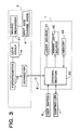
- Fig. 3 is a block diagram of essential portions of a control system.
- An apparatus main body 1 holds therein a laser source 31, an aiming light source 32, a light delivery system, and a control section 30 and others.
- An optical fiber 2 delivers treatment laser beams (hereinafter, referred to as laser beams) emitted by the laser source 31 and an aiming light emitted by the aiming light source 32 to an irradiation optical system 3a of a slit lamp delivery 3.
- the slit lamp delivery 3 is provided with the irradiation optical system 3a for delivering laser beams to an affected part of the patent's eye E, a binocular observation optical system 3b for observing the patent's eye E by a variety of optical systems, and an illumination optical system 3c for slit-illuminating the patient's eye E.
- the irradiation optical system 3a is constructed of a fixed lens group 10, a variable magnification lens group 11 for changing a spot size, an objective lens group 12, and a driving mirror 13.
- the variable magnification lens group 11 is constructed of a lens 11a and a pair of lenses 11b.
- the driving mirror 13 is driven by a manipulator 5, thus moving a spot irradiation position.
- Fig. 8 is a cross sectional view of a lens moving mechanism 41 for moving the variable magnification lens group 11.
- This lens moving mechanism 41 is provided with a hollow fixed mount 42 fixedly mounted in the main body 1 by screws.
- the fixed lens group 10 constructed of three lenses is secured in the fixed mount 42 at its upper part.
- a second movable mount 43 for fixedly supporting the pair of lenses 11b is held movably in the optical axis direction.
- a first movable mount 45 for fixedly supporting the lens 11a is also held movably in the optical axis direction above the second movable mount 43.
- a rotary mount 44 is rotatably mounted on the outer periphery of the fixed mount 42.
- the rotary mount 44 is provided with a gear 44a on the outer periphery.
- a potentiometer 14 is provided to detect a rotational angle of the rotary mount 44 as a movement quantity of lens group 11.
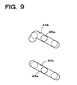
- the rotary mount 44 is provided with grooved cams 44b and 44c as shown in Fig. 9.
- a cam follower 45a attached to the first movable mount 45 is engaged.
- a cam follower 43a attached to the second movable mount 43 is engaged.
- a foot switch 6 generates a trigger signal for laser irradiation when an operator depresses.
- a controller 7 has a variety of switches for setting laser irradiation conditions and a display section for displaying a variety of information for laser irradiation.
- a control section 30 to be connected to the controller 7 controls the devices such as the light source 31 and others according to the settings of the controller 7.
- a cable 8 is provided between the slit lamp delivery 3 and the main body 1. This cable 8 serves to transmit spot size change information and an instruction signal by a change knob 4.
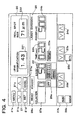
- Fig. 4 is a plan view of the controller 7.
- Reference numeral 20 denotes a liquid crystal display section for displaying a variety of data associated with a contact lens used for laser treatment or a disease case.
- Reference numeral 21 denotes a selection item setting switch group for determining and canceling a selection item displayed on the display section 20.
- Reference numeral 22 denotes a display section for displaying a spot size. A value is displayed on this display section 22 when a movement quantity of the lens group 11 moved by the change knob 4 is detected by the potentiometer 14 and is converted as the size at a focal position in air by means of the control section 30.
- Reference numeral 23a denotes a switch for setting a laser irradiation (coagulation) time, which is displayed on a display section 23b.
- Reference numeral 24a denotes a switch for setting laser output, which is displayed on a display section 24b.
- the controller 7 is provided with a REPEAT lamp 25a for displaying repeating irradiation, an INTVL switch 25b for setting ON or OFF of the repeating irradiation or setting the pause time of the repeating irradiation, an aiming light illumination level display section 26a, a switch 26b for setting the illumination level of the aiming light, a counter 27 for counting the count of laser irradiation, a reset switch 27b for resetting the count, a display section 28a for indicating a READY state (laser irradiation enable state) and a STANDBY state (laser irradiation standby state), a STATUS switch 28b for switching the state, and a display section 29 which always lights while power is supplied (during operation) or the like.
- a REPEAT lamp 25a for displaying repeating irradiation
- an INTVL switch 25b for setting ON or OFF of the repeating irradiation or setting the pause time of the
- laser irradiation conditions Prior to a laser treatment operation, laser irradiation conditions are set by means of the controller 7. At this time, when a MENU switch 21a is pressed if information on the laser irradiation conditions for a disease case of the patent's eye E or information concerning a contact lens to be used for treatment operation is required.
- a menu item selection screen 200 as shown in Fig. 5 is displayed, and the selection items are displayed in reverse video.
- a menu item is selected by operating switches 21b and 21c and moving the reversed display.
- the next menu can be advanced by pressing a SET switch 21d, and then desired information can be displayed by repeated operation.
- the immediately preceding menu can be returned by pressing a CANCEL switch 21e, and the first menu screen can be returned by using the MENU switch 21a.
- a variety of information in the menu items is stored in a memory 33, the control section 30 retrieves corresponding information based on a switch signal from the controller 7, and the information is displayed on the display section 20.
- a variety of disease cases for example, retinal breaks (retinal detachment) or diabetic retinopathy and the like
- photocoagulation laser treatment is displayed as a listed menu.
- a disease case targeted for treatment is selected from this list menu, the information on laser irradiation conditions, contact lens or the like suitable to that disease case is displayed.
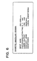
- Fig. 6 is a display example thereof, on which spot size, irradiation power (laser output), coagulation time, contact lens type, and information concerning anesthesia are displayed.
- the condition settings for performing adequate treatment can be easily conducted. More detailed irradiation conditions may be set by allowing input of a variety of data such as patent's age, position of the affected part or the like.
- a contact lens manufacturers list menu is displayed.
- a list menu indicating the types of contact lenses supplied by the selected manufacturer is then displayed.
- the information such as contact lens power, magnification, features or the like is displayed on a display field 210 as shown in an example of the screen of Fig. 7.
- the calculation result concerning the real spot size in the fundus of the patient's eye E is displayed. This real spot size is calculated by the control section 30 based on the spot size data set by the change knob 4 and the selected contact lens magnification data (stored in advance in the memory 33).
- the real irradiation size (spot size) which varies depending on the contact lens used for treatment can be confirmed by inputting contact lens magnification instead of being calculated from the manufacturer's name or type.
- an item 203 "Input contact lens magnification" from the menu screen 200 is selected.
- the magnification of the contact lens to be used can be directly inputted.
- the contact lens magnification can be inputted by increasing or decreasing the value for magnification of the display field 221 by means of the switches 21b and 21c.
- the control section 30 Based on the inputted magnification value and the data of the spot size set by the change knob 4, the control section 30 calculates the real spot size, and the calculation result is displayed on a display field 222.
- the operator can easily recognize the actual irradiation size without performing cumbersome calculation, and can perform the treatment operation on the patient's eye smoothly.
- the change knob 4 the value for the spot size displayed on the display section 20 is changed accordingly.
- the rotary mount 44 is rotated with respect to the fixed mount 42.
- This rotational angle of the rotary mount 44 is detected by the potentiometer 14.
- the cam follower 45a tracks the grooved cam 44b, causing the first movable mount 45 to move on the optical axis by a quantity corresponding to the inclination of the grooved cam 44b.
- the lens 11a is then moved by a predetermined quantity.
- the cam follower 43a tracks the grooved cam 44c, causing the second movable mount 43 to move on the optical axis by a quantity corresponding to the inclination of the grooved cam 44c.
- the lens 11b is then moved by a predetermined quantity.
- the lenses 11a and 11b are moved by a predetermined quantity respectively, thereby changing the spot size.
- the operator when the operator successfully obtains treatment information in advance, the operator performs necessary settings such as laser irradiation conditions by means of the controller 7 with reference to the information.
- a selected contact lens CL is brought into contact with the patent's eye E.
- the operator While observing the patient's eye E through the observation optical system 3c, the operator operates the apparatus to adjust the aiming light to the affected part of the patient's eye E.
- the operator depresses the foot switch 6.
- the laser beams are emitted from the laser source 31 in accordance with the conditions set by means of the controller 7.
- the laser beams delivered in the optical fiber 2 is emitted from an emitting end 2a thereof, and is irradiated to the affected part of the patient's eye E via the irradiation optical system 3a and the contact lens CL.
- the laser treatment apparatus in the present embodiment makes it possible for the operator to easily know the information on the real spot size which varies depending on a contact lens to be used in the treatment operation, and to easily set the laser irradiation conditions adequate for various disease cases. Thus, the operator can smoothly carry out the laser treatment with the laser treatment apparatus.
- the present invention may be embodied in other specific forms without departing from the spirit or essential characteristics thereof.
- the operator performs a switch operation and condition settings by referring to the information on the laser irradiation conditions displayed by inputting the disease case. If an attempt is made so as to automatically set the laser irradiation conditions displayed when the disease case is inputted, the input operation can be more simplified.
- the information on laser irradiation conditions or the like displayed in response to the disease case input can be stored so that the data concerning a variety of disease cases is suitable to the operator by providing an input device making it possible for the operator to arbitrarily change and newly add information so that the inputted data is stored in a memory.
- the laser treatment apparatus is provided with an input device for allowing an operator to arbitrarily change the information on laser irradiation conditions displayed when the disease case is selected or to add new cases, and the changed or added data is stored in the memory, the data on various disease cases can be accumulated successively in response to the operator's needs.
- the laser treatment apparatus can be applied to other treatment employed for a contact lens, for example, laser iridotomy or laser trabeculoplasty (LTP) similarly.
- LTP laser trabeculoplasty
- a laser treatment apparatus for emitting a single wavelength is described, in the case of a multiple wavelength type laser treatment apparatus such as Ar/Kr (Argon/Krypton), Ar/Dye (Argon/Dye), MW/Kr (Multi-wave/Krypton) lasers, an optimal wavelength for the disease case may be displayed together.
- Ar/Kr Ar/Krypton
- Ar/Dye Ar/Dye
- MW/Kr Multi-wave/Krypton
- Data concerning the disease cases and contact lens may be displayed and stored by an external apparatus (personal computer or the like) independent of the laser apparatus main body in a manner that the data is transferred to the laser apparatus main body.
- an external apparatus personal computer or the like
- a variety of information including the patient information such as disease case displayed on the display section 20, selected contact lens information, irradiation conditions displayed, actual irradiation conditions (laser output value, spot size, irradiation time, and irradiation count), etc. can be printed out through a printer, and stored. This information can be printed out, and also can be stored in an external storage medium such as floppy disk.
Landscapes
- Health & Medical Sciences (AREA)
- Ophthalmology & Optometry (AREA)
- Optics & Photonics (AREA)
- Physics & Mathematics (AREA)
- Heart & Thoracic Surgery (AREA)
- Surgery (AREA)
- Engineering & Computer Science (AREA)
- Biomedical Technology (AREA)
- Nuclear Medicine, Radiotherapy & Molecular Imaging (AREA)
- Vascular Medicine (AREA)
- Life Sciences & Earth Sciences (AREA)
- Animal Behavior & Ethology (AREA)
- General Health & Medical Sciences (AREA)
- Public Health (AREA)
- Veterinary Medicine (AREA)
- Laser Surgery Devices (AREA)
- Radiation-Therapy Devices (AREA)
Claims (8)
- Laserbehandlungsgerät zum Bestrahlen eines befallenen Teiles eines Auges (E) mit einem Behandlungslaserstrahl, der von einer Laserquelle (31) emittiert wird und von der Laserquelle (31) über ein optisches System (2, 3a) zu dem befallenen Teil geliefert wird,gekennzeichnet durchwobei das optische System (2, 3a) eine Kontaktlinse (CL) und eine Änderungsvorrichtung (11) zum Ändern einer Lichtfleckgröße des Laserstrahles enthält, undwobei das Laserbehandlungsgerät eine erste Eingabeeinrichtung (21; 203) zum Eingeben von Daten, die sich auf die Vergrößerung der für die Behandlung zu benutzenden Kontaktlinse beziehen, und eine zweite Eingabeeinrichtung (4) zum Eingeben der Lichtfleckgröße des Laserstrahles in Luft enthält,eine Berechnungseinrichtung (30) zum Erhalten einer tatsächlichen Lichtfleckgröße auf dem befallenen Teil auf der Grundlage der von der ersten Eingabeeinrichtung (21; 203) und von der zweien Eingabeeinrichtung eingegebenen Daten; undeine Lichtfleckgrößenanzeigeeinrichtung (20; 222, 211) zum Anzeigen der realen Lichtfleckgröße des Laserstrahles, die von der Berechnungseinrichtung (30) erhalten wird.
- Laserbehandlungsgerät nach Anspruch 1, bei dem die Änderungsvorrichtung (11) eine bewegbare Linse (11a, 11b) auf einer optischen Achse des optischen Systemes (3a) enthält und die zweite Eingabeeinrichtung eine Erfassungseinrichtung (14) zum Erfassen einer Bewegungsgröße der Linse (11a, 11b) enthält und die erfaßte Bewegungsgröße der Linse an die Berechnungseinrichtung eingibt.
- Laserbehandlungsgerät nach Anspruch 1 oder 2, bei dem die erste Eingabeeinrichtung enthält:einen Kontaktlinsendatenspeicher (33), der eine Mehrzahl von Typen von Kontaktlinsen, die für die Behandlung zu benutzen sind, und Daten bezüglich der Vergrößerungen einer jeden Kontaktlinse speichern kann;eine Kontaktlinsenauswahleinrichtung (21; 202) zum Auswählen eines gewünschten Kontaktlinsentypes aus den in dem Speicher (33) gespeicherten Kontaktlinsentypen; undeine Leseeinrichtung (30) zum Auslesen von Daten bezüglich der Vergrößerung des ausgewählten Kontaktlinsentypes aus den die Vergrößerungen betreffenden Daten, die in dem Speicher gespeichert sind.
- Laserbehandlungsgerät nach einem der Ansprüche 1 bis 3, weiter mit:einem Krankheitsfalldatenspeicher (33), der eine Mehrzahl von Typen von zu behandelnden Krankheitsfällen und Daten bezüglich von Laserstrahlbestrahlungsbedingungen entsprechend eines jeden Krankheitsfalles speichern kann;einer Krankheitsfallauswahleinrichtung (21; 201) zum Auswählen eines zu behandelnden Krankheitsfalltypes aus den in dem Speicher gespeicherten Krankheitsfalltypen; undeiner Bestrahlungsbedingungsanzeigeeinrichtung (20) zum Anzeigen von Daten, die die Bestrahlungsbedingung entsprechend des ausgewählten Krankheitsfalltypes betreffen.
- Laserbehandlungsgerät nach Anspruch 4, bei dem die die Bestrahlungsbedingungen betreffenden Daten mindestens Daten enthalten, die sich auf die Bestrahlungsleistung, die Bestrahlungszeit und einer Lichtfleckgröße des Laserstrahles beziehen,
wobei das Laserbehandlungsgerät weiter enthält:
eine Bestrahlungssteuereinrichtung (30) zum Steuern der Laserbestrahlung auf der Grundlage der die Bestrahlungsbedingung betreffenden Daten entsprechend dem ausgewählten Krankheitsfalltyp. - Laserbehandlungsgerät nach Anspruch 4, bei dem die die Bestrahlungsbedingungen betreffenden Daten einen für die Behandlung zu benutzenden Kontaktlinsentyp enthalten und die Kontaktlinsenauswahleinrichtung (21; 202) einen Kontaktlinsentyp auf der Grundlage der die Bestrahlungsbedingung betreffenden Daten entsprechend dem ausgewählten Krankheitsfalltyp auswählt.
- Laserbehandlungsgerät nach einem der Ansprüche 1 bis 3, weiter mit:einem Krankheitsfalldatenspeicher (33), der eine Mehrzahl von Typen von zu behandelnden Krankheitsfällen und Daten bezüglich der Laserstrahlbestrahlungsbedingungen entsprechend einem jeden Krankheitsfall speichern kann, wobei die die Bestrahlungsbedingungen betreffenden Daten mindestens Daten über die Bestrahlungsleistung, die Bestrahlungszeit und eine Lichtfleckgröße des Laserstrahles enthalten;einer Krankheitsfallauswahleinrichtung (21; 201) zum Auswählen eines zu behandelnden Krankheitsfalltypes aus den in dem Speicher gespeicherten Krankheitsfalltypen; undeiner Bestrahlungssteuereinrichtung (30) zum Steuern der Laserbestrahlung auf der Grundlage der die Bestrahlungsbedingung betreffenden Daten entsprechend dem ausgewählten Krankheitsfalltyp.
- Laserbehandlungsgerät nach Anspruch 7, bei dem die die Strahlungsbedingungen betreffenden Daten weiter einen für die Behandlung zu benutzenden Kontaktlinsentyp enthalten und die Kontaktlinsenauswahleinrichtung einen Kontaktlinsentyp auf der Grundlage der die Bestrahlungsbedingung betreffenden Daten entsprechend dem ausgewählten Krankheitsfalltyp auswählt.
Applications Claiming Priority (2)
| Application Number | Priority Date | Filing Date | Title |
|---|---|---|---|
| JP10148911A JPH11332905A (ja) | 1998-05-29 | 1998-05-29 | レーザ治療装置及びレーザ治療情報表示装置 |
| JP14891198 | 1998-05-29 |
Publications (2)
| Publication Number | Publication Date |
|---|---|
| EP0960609A1 EP0960609A1 (de) | 1999-12-01 |
| EP0960609B1 true EP0960609B1 (de) | 2001-10-10 |
Family
ID=15463425
Family Applications (1)
| Application Number | Title | Priority Date | Filing Date |
|---|---|---|---|
| EP99110313A Expired - Lifetime EP0960609B1 (de) | 1998-05-29 | 1999-05-27 | Einrichtung zur Laserbehandlung |
Country Status (4)
| Country | Link |
|---|---|
| US (1) | US6346100B1 (de) |
| EP (1) | EP0960609B1 (de) |
| JP (1) | JPH11332905A (de) |
| DE (1) | DE69900340T2 (de) |
Families Citing this family (16)
| Publication number | Priority date | Publication date | Assignee | Title |
|---|---|---|---|---|
| JP3889904B2 (ja) * | 1999-08-05 | 2007-03-07 | 株式会社ニデック | 光凝固装置 |
| JP3730454B2 (ja) * | 1999-09-21 | 2006-01-05 | 株式会社ニデック | レーザ装置 |
| DE10015157A1 (de) * | 2000-03-27 | 2001-10-18 | P A L M Gmbh | Verfahren zur Bearbeitung einer biologischen Masse und Steuersystem für eine Vorrichtung zur Bearbeitung einer biologischen Masse |
| US7150530B2 (en) * | 2003-05-21 | 2006-12-19 | Alcon, Inc. | Variable spot size illuminator having a zoom lens |
| US7903777B1 (en) | 2004-03-03 | 2011-03-08 | Marvell International Ltd. | System and method for reducing electromagnetic interference and ground bounce in an information communication system by controlling phase of clock signals among a plurality of information communication devices |
| DE102005013949A1 (de) | 2005-03-26 | 2006-09-28 | Carl Zeiss Meditec Ag | Scanvorrichtung |
| WO2008045539A2 (en) * | 2006-10-11 | 2008-04-17 | Lumenis Ltd. | Laser treatment procedure atlas |
| JP4970068B2 (ja) * | 2007-01-30 | 2012-07-04 | 株式会社ニデック | 眼科用レーザ治療装置 |
| US7802883B2 (en) * | 2007-12-20 | 2010-09-28 | Johnson & Johnson Vision Care, Inc. | Cosmetic contact lenses having a sparkle effect |
| US9849034B2 (en) | 2011-11-07 | 2017-12-26 | Alcon Research, Ltd. | Retinal laser surgery |
| JP6540091B2 (ja) | 2015-02-26 | 2019-07-10 | 株式会社ニデック | 眼科用レーザ治療装置 |
| JP6499883B2 (ja) * | 2015-03-05 | 2019-04-10 | 株式会社トプコン | レーザ治療装置 |
| DE102015205696A1 (de) * | 2015-03-30 | 2016-10-06 | Carl Zeiss Meditec Ag | Ophthalmologische Lasertherapievorrichtung |
| JP6830810B2 (ja) * | 2016-12-27 | 2021-02-17 | 株式会社トプコン | 眼科レーザシステム |
| CN107550564B (zh) * | 2017-10-31 | 2023-11-21 | 重庆京渝激光技术有限公司 | 用于激光治疗机的治疗头 |
| CN111772576A (zh) * | 2020-07-16 | 2020-10-16 | 上海市静安区闸北中心医院 | 一种视网膜激光光凝治疗记录系统 |
Family Cites Families (18)
| Publication number | Priority date | Publication date | Assignee | Title |
|---|---|---|---|---|
| US4750829A (en) * | 1986-05-09 | 1988-06-14 | Wise James B | Iridotomy-sphincterotomy contact lens |
| US4839822A (en) * | 1987-08-13 | 1989-06-13 | 501 Synthes (U.S.A.) | Computer system and method for suggesting treatments for physical trauma |
| US5098426A (en) * | 1989-02-06 | 1992-03-24 | Phoenix Laser Systems, Inc. | Method and apparatus for precision laser surgery |
| US6099522A (en) * | 1989-02-06 | 2000-08-08 | Visx Inc. | Automated laser workstation for high precision surgical and industrial interventions |
| ES2138586T3 (es) | 1990-07-23 | 2000-01-16 | Laser Biotech Inc | Aparato para modificar la forma de la cornea para corregir los errores de refraccion ocular. |
| US5171242A (en) * | 1990-10-26 | 1992-12-15 | Coherent, Inc. | Combination lens system for retinal photocoagulator laser system |
| JP3206923B2 (ja) | 1991-01-30 | 2001-09-10 | 株式会社ニデック | 眼科用レーザ手術装置 |
| JP3201418B2 (ja) * | 1991-07-30 | 2001-08-20 | 株式会社ニコン | 焦点可変装置 |
| US5661816A (en) * | 1991-10-22 | 1997-08-26 | Optikos Corporation | Image analysis system |
| EP0630205A4 (de) | 1992-02-27 | 1995-06-14 | Phoenix Laser Systems Inc | Automatisierte laser-einheit für hochgenaue chirurgische und industrielle eingriffe. |
| DE4320579C2 (de) * | 1992-06-15 | 2000-06-15 | Topcon Corp | Operationsmikroskop |
| US5336215A (en) | 1993-01-22 | 1994-08-09 | Intelligent Surgical Lasers | Eye stabilizing mechanism for use in ophthalmic laser surgery |
| ES2180597T4 (es) | 1994-08-18 | 2003-07-01 | Zeiss Carl | Aparato quirurgico asistido por tomografia de coherencia optica. |
| US5599340A (en) * | 1994-12-09 | 1997-02-04 | Simon; Gabriel | Laser beam ophthalmological surgery method and apparatus |
| JP3688339B2 (ja) | 1995-02-28 | 2005-08-24 | 株式会社ニデック | レ−ザ治療装置 |
| WO1997031567A1 (en) * | 1996-03-01 | 1997-09-04 | Medicomp Of Virginia, Inc. | Intelligent prompting |
| US5843070A (en) * | 1996-05-13 | 1998-12-01 | Partech, Inc. | Simulating corneal laser surgery |
| JP2895014B2 (ja) | 1997-01-23 | 1999-05-24 | 日本電気株式会社 | イオンレーザ装置 |
-
1998
- 1998-05-29 JP JP10148911A patent/JPH11332905A/ja not_active Withdrawn
-
1999
- 1999-05-25 US US09/318,253 patent/US6346100B1/en not_active Expired - Fee Related
- 1999-05-27 DE DE69900340T patent/DE69900340T2/de not_active Expired - Lifetime
- 1999-05-27 EP EP99110313A patent/EP0960609B1/de not_active Expired - Lifetime
Also Published As
| Publication number | Publication date |
|---|---|
| EP0960609A1 (de) | 1999-12-01 |
| JPH11332905A (ja) | 1999-12-07 |
| DE69900340D1 (de) | 2001-11-15 |
| US6346100B1 (en) | 2002-02-12 |
| DE69900340T2 (de) | 2002-06-27 |
Similar Documents
| Publication | Publication Date | Title |
|---|---|---|
| EP0960609B1 (de) | Einrichtung zur Laserbehandlung | |
| US7229435B2 (en) | Ophthalmic laser treatment apparatus | |
| US5226903A (en) | Apparatus for ophthalmic operation using photocoagulation by a laser beam | |
| US8382743B2 (en) | Ophthalmic laser treatment apparatus | |
| US7393349B2 (en) | Ophthalmic laser treatment apparatus | |
| US9308129B2 (en) | Ophthalmic laser treatment apparatus | |
| JP5627898B2 (ja) | 眼科用レーザ治療装置 | |
| JPH09149914A (ja) | 眼科手術装置 | |
| US6325793B1 (en) | Laser treatment apparatus | |
| EP1088523B1 (de) | Laserbehandlungsgerät mit Anwender-Anwesenheitskontrolle | |
| JP3892986B2 (ja) | 眼科用レーザ治療装置 | |
| EP1228740B1 (de) | Laseraugenbehandlungseinrichtung | |
| JP3892984B2 (ja) | レーザ光凝固装置 | |
| JP2000217839A (ja) | レーザ治療装置 | |
| JP4054538B2 (ja) | レーザ治療装置 | |
| JP2003019158A (ja) | レーザー治療用眼科装置 | |
| JP3974824B2 (ja) | 眼科検査装置 | |
| JPH07236652A (ja) | 眼科手術装置 | |
| JP7099848B2 (ja) | 眼科レーザシステム | |
| JP2000152955A (ja) | 眼科用レーザ装置 | |
| JP2003190203A (ja) | 眼科用レーザ治療装置 | |
| JP2002186640A (ja) | レーザ治療装置 | |
| JPH11276500A (ja) | レーザ治療装置 |
Legal Events
| Date | Code | Title | Description |
|---|---|---|---|
| PUAI | Public reference made under article 153(3) epc to a published international application that has entered the european phase |
Free format text: ORIGINAL CODE: 0009012 |
|
| AK | Designated contracting states |
Kind code of ref document: A1 Designated state(s): DE FR GB |
|
| AX | Request for extension of the european patent |
Free format text: AL;LT;LV;MK;RO;SI |
|
| 17P | Request for examination filed |
Effective date: 20000504 |
|
| AKX | Designation fees paid |
Free format text: DE FR GB |
|
| 17Q | First examination report despatched |
Effective date: 20000712 |
|
| GRAG | Despatch of communication of intention to grant |
Free format text: ORIGINAL CODE: EPIDOS AGRA |
|
| GRAG | Despatch of communication of intention to grant |
Free format text: ORIGINAL CODE: EPIDOS AGRA |
|
| GRAH | Despatch of communication of intention to grant a patent |
Free format text: ORIGINAL CODE: EPIDOS IGRA |
|
| GRAH | Despatch of communication of intention to grant a patent |
Free format text: ORIGINAL CODE: EPIDOS IGRA |
|
| GRAA | (expected) grant |
Free format text: ORIGINAL CODE: 0009210 |
|
| AK | Designated contracting states |
Kind code of ref document: B1 Designated state(s): DE FR GB |
|
| REF | Corresponds to: |
Ref document number: 69900340 Country of ref document: DE Date of ref document: 20011115 |
|
| ET | Fr: translation filed | ||
| REG | Reference to a national code |
Ref country code: GB Ref legal event code: IF02 |
|
| PLBI | Opposition filed |
Free format text: ORIGINAL CODE: 0009260 |
|
| PLBF | Reply of patent proprietor to notice(s) of opposition |
Free format text: ORIGINAL CODE: EPIDOS OBSO |
|
| 26 | Opposition filed |
Opponent name: CARL ZEISS JENA GMBH Effective date: 20020709 |
|
| PLBF | Reply of patent proprietor to notice(s) of opposition |
Free format text: ORIGINAL CODE: EPIDOS OBSO |
|
| APBP | Date of receipt of notice of appeal recorded |
Free format text: ORIGINAL CODE: EPIDOSNNOA2O |
|
| APBQ | Date of receipt of statement of grounds of appeal recorded |
Free format text: ORIGINAL CODE: EPIDOSNNOA3O |
|
| APAY | Date of receipt of notice of appeal deleted |
Free format text: ORIGINAL CODE: EPIDOSDNOA2O |
|
| APBA | Date of receipt of statement of grounds of appeal deleted |
Free format text: ORIGINAL CODE: EPIDOSDNOA3O |
|
| PLAB | Opposition data, opponent's data or that of the opponent's representative modified |
Free format text: ORIGINAL CODE: 0009299OPPO |
|
| PLAB | Opposition data, opponent's data or that of the opponent's representative modified |
Free format text: ORIGINAL CODE: 0009299OPPO |
|
| R26 | Opposition filed (corrected) |
Opponent name: WABCO GMBH & CO. OHG Effective date: 20020709 |
|
| R26 | Opposition filed (corrected) |
Opponent name: CARL ZEISS JENA GMBH Effective date: 20020709 |
|
| PLBQ | Unpublished change to opponent data |
Free format text: ORIGINAL CODE: EPIDOS OPPO |
|
| PLAB | Opposition data, opponent's data or that of the opponent's representative modified |
Free format text: ORIGINAL CODE: 0009299OPPO |
|
| APBP | Date of receipt of notice of appeal recorded |
Free format text: ORIGINAL CODE: EPIDOSNNOA2O |
|
| APBQ | Date of receipt of statement of grounds of appeal recorded |
Free format text: ORIGINAL CODE: EPIDOSNNOA3O |
|
| R26 | Opposition filed (corrected) |
Opponent name: CARL ZEISS JENA GMBH Effective date: 20020709 |
|
| PLAY | Examination report in opposition despatched + time limit |
Free format text: ORIGINAL CODE: EPIDOSNORE2 |
|
| PLAY | Examination report in opposition despatched + time limit |
Free format text: ORIGINAL CODE: EPIDOSNORE2 |
|
| PLBC | Reply to examination report in opposition received |
Free format text: ORIGINAL CODE: EPIDOSNORE3 |
|
| APAH | Appeal reference modified |
Free format text: ORIGINAL CODE: EPIDOSCREFNO |
|
| PLCK | Communication despatched that opposition was rejected |
Free format text: ORIGINAL CODE: EPIDOSNREJ1 |
|
| PLBN | Opposition rejected |
Free format text: ORIGINAL CODE: 0009273 |
|
| STAA | Information on the status of an ep patent application or granted ep patent |
Free format text: STATUS: OPPOSITION REJECTED |
|
| 27O | Opposition rejected |
Effective date: 20060321 |
|
| PGFP | Annual fee paid to national office [announced via postgrant information from national office to epo] |
Ref country code: GB Payment date: 20080528 Year of fee payment: 10 |
|
| GBPC | Gb: european patent ceased through non-payment of renewal fee |
Effective date: 20090527 |
|
| REG | Reference to a national code |
Ref country code: FR Ref legal event code: ST Effective date: 20100129 |
|
| PG25 | Lapsed in a contracting state [announced via postgrant information from national office to epo] |
Ref country code: FR Free format text: LAPSE BECAUSE OF NON-PAYMENT OF DUE FEES Effective date: 20090602 |
|
| PGFP | Annual fee paid to national office [announced via postgrant information from national office to epo] |
Ref country code: FR Payment date: 20080514 Year of fee payment: 10 |
|
| PG25 | Lapsed in a contracting state [announced via postgrant information from national office to epo] |
Ref country code: GB Free format text: LAPSE BECAUSE OF NON-PAYMENT OF DUE FEES Effective date: 20090527 |
|
| PGFP | Annual fee paid to national office [announced via postgrant information from national office to epo] |
Ref country code: DE Payment date: 20140521 Year of fee payment: 16 |
|
| REG | Reference to a national code |
Ref country code: DE Ref legal event code: R119 Ref document number: 69900340 Country of ref document: DE |
|
| PG25 | Lapsed in a contracting state [announced via postgrant information from national office to epo] |
Ref country code: DE Free format text: LAPSE BECAUSE OF NON-PAYMENT OF DUE FEES Effective date: 20151201 |