EP0960671A2 - Strangführungssegment für Brammengiessanlagen - Google Patents
Strangführungssegment für Brammengiessanlagen Download PDFInfo
- Publication number
- EP0960671A2 EP0960671A2 EP99110206A EP99110206A EP0960671A2 EP 0960671 A2 EP0960671 A2 EP 0960671A2 EP 99110206 A EP99110206 A EP 99110206A EP 99110206 A EP99110206 A EP 99110206A EP 0960671 A2 EP0960671 A2 EP 0960671A2
- Authority
- EP
- European Patent Office
- Prior art keywords
- segment
- strand
- frame
- cylinder
- guide
- Prior art date
- Legal status (The legal status is an assumption and is not a legal conclusion. Google has not performed a legal analysis and makes no representation as to the accuracy of the status listed.)
- Granted
Links
Images


Classifications
-
- B—PERFORMING OPERATIONS; TRANSPORTING
- B22—CASTING; POWDER METALLURGY
- B22D—CASTING OF METALS; CASTING OF OTHER SUBSTANCES BY THE SAME PROCESSES OR DEVICES
- B22D11/00—Continuous casting of metals, i.e. casting in indefinite lengths
- B22D11/12—Accessories for subsequent treating or working cast stock in situ
- B22D11/128—Accessories for subsequent treating or working cast stock in situ for removing
Definitions
- the invention relates to a strand guide segment for Slab caster with one between guide rollers fixed frame and a loose frame distance-adjustable guide width for the casting strand, where the frames for overcoming the ferrostatic pressure and for Setting the desired format width of the strand with Interacting means interact.
- Continuous casting plants in particular for casting steel slabs, use rollers to guide the strand, one more not limit solidified strand in its thickness and one Bulging of the strand shell due to the ferrostatic Prevent internal pressure.
- DE 196 27 336 C1 describes one method and one Device for guiding a strand in a Continuous caster with a "soft reduction line" known, with the hydraulic servo units the mouth width of the Continuously adjust opposite strand guide rollers.
- the well-known strand guide which is four per segment Servo piston cylinder units for stepless adjustment of the Mouth width of the opposite strand guide rollers has, is characterized in that hydraulic lines Ring surfaces and piston surfaces of two neighboring ones Servo piston cylinder units with a common servo valve connect, and that position transmitter's with a common Servo valve controlled servo piston cylinder units are technically interlinkable.
- the clamping cylinders are usually on the side of the segment arranged the roles and are therefore inclusive of hydraulic lines and servo valves Servo piston cylinder units in the area of Radiation exposure of the casting strand. You need to consequently at such a distance - middle segment - Hydraulic cylinder - be arranged that the Radiation exposure remains limited.
- the one for this required frame width of the segment leads because of The load on the frame is comparatively heavy construction, which the cost of manufacturing and Assembly and the scaffolding costs significantly burdened.
- the invention lies Task, a strand guide for Slab casting plants mentioned in the preamble of claim 1 Art significantly compared to conventional designs Simplify to do this with impression cylinders through their Storage in the area of the upper frame outside the cooling chamber are and with a lighter frame construction and simplified water cooling system and piping for the roller cooling contributes a substantial saving in costs Manufacture and assembly of the strand guide elements achieve.
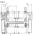
- the strand guide segment shown in Figure 1 for Slab caster has one between guide rollers (1) loose side frame (3) and guide rollers (1 ') one fixed frame (2) an adjustable distance Guide width (F) for the casting strand (10), the Frame (2, 3) to overcome the ferrostatic pressure and for setting the desired format width of the strand (10) interact with actuators.
- adjustable pressure cylinders (4, 4 '; 5, 5') are provided and outside the radiation range at the top of the Segment arranged, the one determining the segment width Distance (A) segment center cylinder by the amount of the to the Top of the segment shifted cylinder (4, 5) on both sides is narrowed.
- FIG. 1 shows and 2 the connection of one printing cylinder (4) or (5) on the side frame (11) with the help of a universal joint (15).
- Fig. 1 shows the connection of the guide frame (2) over the subframe (8) with the Side frame (11) into a compact structural unit.
- Fig. 1 shows the connection of the guide frame (2) over the subframe (8) with the Side frame (11) into a compact structural unit.
- the Pipe guide for cooling the rollers (1, 1 ') essential simplified. Between the guide rollers (1) in Fig. 2 is the of this led casting strand (10) with dash-dotted Lines indicated.
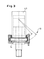
- Figure 3 shows a standard printing cylinder (4, 5), the Flange (14) in a spherical cap Guide (13) is added. But also a rigid one Attachment according to Figure 3a is when articulated Cardan double joint on the loose frame (3) expedient. With it and with the gimbal connection of the Cardan joint (15) according to FIGS. 1 and 2 and in particular Fig. 3a results in an optimal adhesion between one Cylinder (4, 4 '; 5, 5') and one of the side frames (11) without lateral constraint.
- Figure 4 shows the advantageous use of Radiation protection plates (7) on trusses (6) of the Strand guide segment.
- the illustration demonstrates in convincingly after with the radiation protection plates (7) simplification achievable compared to the invention water-cooled segment cross members.
- the invention is comparatively uncomplicated Construction very well suited to the task at the beginning realize and solve them in an optimal way.
Landscapes
- Engineering & Computer Science (AREA)
- Mechanical Engineering (AREA)
- Continuous Casting (AREA)
Abstract
Description
- der Oberrahmen bei biegungs- und verwindungssteifer Ausführung in allen Achsen schwenkbar ist, wobei
- eine Anstellung des Oberrahmens mit exakter Maßhaltigkeit der gewünschten Maulweitengeometrie von Dicke und Neigung in Längs- und Breitachse möglich ist,
- die Hydraulikzylinder als Druckzylinder mit vergleichsweise kleinem Durchmesser ausbildbar sind, um bei dadurch verkürztem Hebelarm das Lastmoment zu reduzieren, wobei
- die Zylinder einschließlich ihrer Mess- und Regelorgane außerhalb der Kühlkammer liegen, und wobei
- die äußeren Segmentrollen infolge der geänderten Bauweise antreibbar sind,
- wodurch zugleich mit optimaler Funktionserfüllung ein kostengünstiger Segmenttyp entsteht, der dem konventionellen Typ mit Zugzylindern überlegen ist und ihn ersetzt.
- dass als Stellmittel vier unabhängig einstellbare Druckzylinder vorgesehen und außerhalb des Strahlungsbereiches an der Oberseite des Segmentes angeordnet sind, wobei der die Segmentbreite bestimmende Abstand Segmentmitte-Zylinder um das Maß des an die Oberseite des Segmentes verlagerten Zylinders beidseitig verschmälert ist, und
- dass die Segmenttraversen anstelle von Wasserkühlung mit Strahlenschutzblechen versehen sind, sowie
- dass seitlich an den Unterrahmen gekühlte Seitenrahmen angeflanscht sind.
- dass ein kastenförmiges Rahmen-Seitenteil als wasserführender Kanal ausgebildet ist, und
- dass Wasseranschlüsse für die Rollenkühlung an einer Seite des Strangführungselementes angeordnet sind. Hiermit werden signifikante Vereinfachungen der Leitungsführung und ihrer Anschlüsse für die Rollenkühlung erzielt. Weitere Vorteile ergeben sich dadurch,
- dass der Oberrahmen biegungs- und verwindungssteif ausgebildet und durch seine kardanische Anlenkung an die Hydraulikzylinder in allen drei Achsen schwenkbar ist,
- dass die Hydraulikzylinder als Druckzylinder im Durchmesser vergleichsweise klein sind, wodurch das Lastmoment infolge Verkürzung des Hebelarms reduziert wird,
- dass mit Ausbildung und starrer Anordnung des Seitenrahmens die Möglichkeit gegeben ist, die Rahmen auf Distanzstücke zu fahren und somit die Rollendistanz beispielsweise entsprechend der Segmentdicke einzustellen,
- dass die Hydraulikzylinder sich außerhalb der Kühlkammer befinden, so dass für diese einschließlich der Mess- und Regelorgane zulässige Temperaturen gegeben sind,
- dass dies auch für die komplett außerhalb der Kühlkammer liegenden Hydraulikverrohrungen und deren Kupplungselemente gilt,
- dass bei Lagerung der Zylinder in den Seitenrahmen bei dynamischer Anstellung des Oberrahmens gegen den Warmstrangdruck (pferro) der Oberrahmen in seinen drei Achsen frei verstellbar und neigbar ist, und zwar mit exakt maßgerechter Positionierung durch dessen kardanische Lagerung, ohne dass hierbei horizontale Zwangskräfte in den Lagerungen bei Anstellvorgängen entstehen.
- Verwendung von vier Druckzylindern oberhalb des Segmentes, d. h. außerhalb des Strahlungsbereiches,
- geringere Segmentbreite durch Verringerung des Abstandes Segmentmitte-Zylinder,
- Verwendung von Strahlenschutzblechen für die Traversen,
- gekühlte Seitenrahmen, seitlich an den Unterrahmen angeflanscht,
- Minimierung der Rohrleitungen durch Nutzung des kastenförmigen Seitenteils zur Wasserführung, Wasseranschlüsse nur auf einer Seite des Segmentes sowie Ersatz der Traversenkühlung durch Strahlenschutzbleche.
- Fig. 1
- in Frontansicht ein Strangführungssegment, teilweise im Schnitt,
- Fig. 2
- das Strangführungssegment gemäß Fig. 1 in Seitenansicht, ebenfalls teilweise im Schnitt,
- Fig. 3
- in Seitenansicht und teilweise im Schnitt einen hydraulischen Druckzylinder mit Lagerung seines Flansches nach Art einer Kugelkalotte,
- Fig. 3a
- in Seitenansicht und teilweise im Schnitt einen hydraulischen Druckzylinder mit unbeweglicher Lagerung und Anbindung an den losseitigen Rahmen über eine Kardan-Doppelgelenkanordnung mit allseitig schwenkbarem Freigang,
- Fig. 4
- in Seitenansicht einen Teil des Strangführungssegmentes mit Segmenttraversen und an diesen angeordneten Strahlenschutzblechen.
Claims (4)
- Strangführungssegment für Brammengießanlagen mit zwischen Führungsrollen (1) eines festseitigen und eines losseitigen Rahmens (2, 3) abstandseinstellbarer Führungsbreite (F) für den Gießstrang (10), wobei die Rahmen (2, 3) zur Überwindung des ferrostatischen Druckes und zur Einstellung der gewünschten Formatbreite des Stranges (10) mit Stellmitteln zusammenwirken, gekennzeichnet durch die Merkmale,dass als Stellmittel vier unabhängig einstellbare Druckzylinder (4, 4'; 5, 5') vorgesehen und außerhalb des Strahlungsbereiches an der Oberseite des Segmentes angeordnet sind, wobei der die Segmentbreite bestimmende Abstand (A) Segmentmitte - Zylinder beidseitig um das Maß des an die Oberseite des Segmentes verlagerten Zylinders (4, 5) verschmälert ist, unddass die Segmenttraversen (6) mit Strahlenschutzblechen (7) versehen sind, sowiedass seitlich an den Unterrahmen (8) wassergekühlte Seitenrahmen (11) angeflanscht sind.
- Strangführungssegment nach Anspruch 1, gekennzeichnet durch die weiteren Merkmale,dass ein kastenförmiges Rahmen-Seitenteil (11) als wasserführender Kanal ausgebildet ist, unddass Wasseranschlüsse (12) für die Rollenkühlung an einer Seite des Strangführungselementes angeordnet sind.
- Strangführungselement nach Anspruch 1 oder 2, dadurch gekennzeichnet, dass Druckzylinder (4, 5) mit ihren Flanschen (14) in einer kugelkalottenförmig ausgebildeten Lagerung (13) angeordnet und an seitlichen Rahmenelementen (11) des Segmentes mittels Kardangelenken (15) angelenkt sind.
- Strangführungselement nach Anspruch 1 oder 2, dadurch gekennzeichnet, dass Druckzylinder (4, 5) an diesem unbeweglich gelagert und über eine Kardan-Doppelgelenkanordnung (15) mit seitlichem Freigang am losseitigen Rahmen (11) angelenkt sind.
Applications Claiming Priority (2)
| Application Number | Priority Date | Filing Date | Title |
|---|---|---|---|
| DE19824366 | 1998-05-30 | ||
| DE19824366A DE19824366A1 (de) | 1998-05-30 | 1998-05-30 | Strangführungssegment für Brammengießanlagen |
Publications (3)
| Publication Number | Publication Date |
|---|---|
| EP0960671A2 true EP0960671A2 (de) | 1999-12-01 |
| EP0960671A3 EP0960671A3 (de) | 2000-11-08 |
| EP0960671B1 EP0960671B1 (de) | 2003-06-25 |
Family
ID=7869496
Family Applications (1)
| Application Number | Title | Priority Date | Filing Date |
|---|---|---|---|
| EP99110206A Expired - Lifetime EP0960671B1 (de) | 1998-05-30 | 1999-05-26 | Strangführungssegment für Brammengiessanlagen |
Country Status (5)
| Country | Link |
|---|---|
| US (1) | US6328093B1 (de) |
| EP (1) | EP0960671B1 (de) |
| JP (1) | JP4298057B2 (de) |
| DE (2) | DE19824366A1 (de) |
| RU (1) | RU2219014C2 (de) |
Families Citing this family (9)
| Publication number | Priority date | Publication date | Assignee | Title |
|---|---|---|---|---|
| DE102005055530A1 (de) * | 2005-11-22 | 2007-05-24 | Sms Demag Ag | Verfahren und Vorrichtung zum Anstellen von mindestens einem Rollensegment einer Strangführungseinrichtung an einen Strang |
| DE102005062854A1 (de) * | 2005-12-23 | 2007-07-05 | Salzgitter Flachstahl Gmbh | Verfahren und Einrichtung zum Erzeugen von metallischen Warmbändern insbesondere aus Leichtbaustahl |
| US7451804B2 (en) * | 2006-11-22 | 2008-11-18 | Peterson Oren V | Method and apparatus for horizontal continuous metal casting in a sealed table caster |
| RU2350426C1 (ru) * | 2007-06-22 | 2009-03-27 | Закрытое акционерное общество "Новокраматорский машиностроительный завод" | Секция роликовая машины непрерывного литья слябовых заготовок |
| DE102008009136A1 (de) * | 2008-02-14 | 2009-10-15 | Sms Siemag Aktiengesellschaft | Strangführung, insbesondere für eine Stahlbrammen-Stranggießanlage |
| JP5217719B2 (ja) * | 2008-07-16 | 2013-06-19 | 新日鐵住金株式会社 | 連続鋳造設備におけるロールセグメント装置 |
| CN105642858A (zh) * | 2016-04-05 | 2016-06-08 | 中国重型机械研究院股份公司 | 铸坯在线调整装置 |
| IT201700032906A1 (it) * | 2017-03-24 | 2018-09-24 | Danieli Off Mecc | Apparato e metodo di cambio di unita' di guida in una macchina di colata continua |
| DE102017219740A1 (de) * | 2017-11-07 | 2019-05-09 | Sms Group Gmbh | Strangführungssegment und Stranggießanlage |
Family Cites Families (17)
| Publication number | Priority date | Publication date | Assignee | Title |
|---|---|---|---|---|
| SU639424A3 (ru) * | 1975-02-04 | 1978-12-25 | Маннесманн Аг, (Фирма) | Способ непрерывной отливки стального слитка |
| GB1584625A (en) * | 1976-07-16 | 1981-02-18 | Concast Ag | Roller guide frame for an installation for the continous casting of steel |
| AT370656B (de) * | 1981-09-17 | 1983-04-25 | Voest Alpine Ag | Stuetz- und fuehrungsbogen fuer gussstraenge |
| DE3303386A1 (de) * | 1983-02-02 | 1984-08-09 | SMS Schloemann-Siemag AG, 4000 Düsseldorf | Stuetzfuehrung in einer stranggiessanlage |
| SU1509171A1 (ru) * | 1987-08-03 | 1989-09-23 | Днепропетровский филиал Всесоюзного научно-исследовательского и проектного института систем автоматизации и управления | Устройство контрол настройки технологического оборудовани машины непрерывного лить заготовок |
| JPH01218756A (ja) * | 1988-02-26 | 1989-08-31 | Sumitomo Metal Ind Ltd | 連続鋳造機のロール間隔制御方法 |
| DE3907905C2 (de) * | 1988-07-04 | 1999-01-21 | Mannesmann Ag | Stranggießverfahren |
| US5152334A (en) * | 1990-05-02 | 1992-10-06 | Mesta International | Guide roll assembly and method of guiding cast strand |
| DE4022871A1 (de) * | 1990-07-18 | 1992-01-23 | Voest Alpine Ind Anlagen | Strangfuehrung an einer stranggiessanlage |
| DE69209656T2 (de) * | 1991-09-12 | 1996-08-29 | Arvedi, Giovanni, Cremona | Verfahren und vorrichtung zur herstellung von stahlstraengen oder-knueppeln durch stranggiessen mit hoher bzw. exzelenter qualitaet |
| ATE138835T1 (de) * | 1991-09-19 | 1996-06-15 | Schloemann Siemag Ag | Verfahren und anlage zur herstellung von stahlband |
| DE4138740A1 (de) * | 1991-11-26 | 1993-05-27 | Schloemann Siemag Ag | Verfahren und vorrichtung zum stranggiessen von brammen oder bloecken |
| JPH05285616A (ja) * | 1992-04-07 | 1993-11-02 | Kobe Steel Ltd | 連続鋳造法における鋳片圧下方法 |
| RU2015826C1 (ru) * | 1992-08-20 | 1994-07-15 | Производственное объединение "Южуралмаш" | Устройство для непрерывной разливки металлов |
| DE4306853C2 (de) * | 1993-02-26 | 1996-03-21 | Mannesmann Ag | Strangführungsgerüst |
| DE19627336C1 (de) | 1996-06-28 | 1997-09-18 | Mannesmann Ag | Verfahren zum Führen eines Stranges und Strangführung |
| JP4219405B2 (ja) * | 1996-08-05 | 2009-02-04 | エスエムエス デマグ インコーポレイテッド | 連続鋳造法のためのガイドセグメント支持システム |
-
1998
- 1998-05-30 DE DE19824366A patent/DE19824366A1/de not_active Withdrawn
-
1999
- 1999-05-26 DE DE59906060T patent/DE59906060D1/de not_active Expired - Fee Related
- 1999-05-26 EP EP99110206A patent/EP0960671B1/de not_active Expired - Lifetime
- 1999-05-26 US US09/320,437 patent/US6328093B1/en not_active Expired - Fee Related
- 1999-05-27 JP JP14803099A patent/JP4298057B2/ja not_active Expired - Fee Related
- 1999-05-27 RU RU99111067/02A patent/RU2219014C2/ru not_active IP Right Cessation
Also Published As
| Publication number | Publication date |
|---|---|
| DE59906060D1 (de) | 2003-07-31 |
| EP0960671B1 (de) | 2003-06-25 |
| JP4298057B2 (ja) | 2009-07-15 |
| DE19824366A1 (de) | 1999-12-02 |
| JP2000000649A (ja) | 2000-01-07 |
| RU2219014C2 (ru) | 2003-12-20 |
| EP0960671A3 (de) | 2000-11-08 |
| US6328093B1 (en) | 2001-12-11 |
Similar Documents
| Publication | Publication Date | Title |
|---|---|---|
| EP1478479B1 (de) | Verfahren zum stranggiessen und unmittelbaren verformen eines metall-, insbesondere eines giessstrangs aus stahlwerkstoffen | |
| EP0960671B1 (de) | Strangführungssegment für Brammengiessanlagen | |
| DE4306853C2 (de) | Strangführungsgerüst | |
| DE1558220C3 (de) | Lagerung von Walzen für die Formänderung eines aus einer Stranggießkokille kommenden metallischen Stranges | |
| EP2285511A1 (de) | Strangführung, insbesondere für eine stahlbrammen-stranggiessanlage | |
| EP3256276B1 (de) | Giessanlage | |
| DE102008010689B4 (de) | Zwei-Walzen-Gießmaschine zum Herstellen von aus einer Metallschmelze gegossenem Band | |
| DE2552969A1 (de) | Fuehrungsrolle fuer stranggussanlagen, mit auf einer mehrfach gelagerten achse angeordneten rollenabschnitten | |
| DE29980239U1 (de) | Walzwerk mit zweidimensional gesteuerter Walzendurchbiegung | |
| DE3117500C2 (de) | Transport- und Richtmaschine einer Stranggießanlage | |
| DE19843038B4 (de) | Vorrichtung zum Kühlen von Walzgut innerhalb der Kühlstrecke einer Walzanlage zur laminarern Bandkühlung | |
| EP2525928B2 (de) | Strangführungselement zum führen und stützen eines metallischen strangs in einer stranggiessmaschine | |
| AT405253B (de) | Stranggiesskokille | |
| AT341129B (de) | Stranggiessanlage | |
| EP3097995B2 (de) | Segment einer strangführung einer stranggiessanlage und stranggiessanlage | |
| EP4489928B1 (de) | Bogensegment einer strangführungseinrichtung | |
| DE3706720A1 (de) | Stranggiessanlage mit zwei nebeneinander angeordneten druchlaufkokillen | |
| EP1337365B1 (de) | Strangführung einer stranggiessanlage mit einer einrichtung zur sekundärkühlung | |
| EP3706933B1 (de) | Strangführungssegment und stranggiessanlage | |
| DE69001260T2 (de) | Verfahren zur abstuetzung und zur regelung der position eines oberriegels in einer form zum druckgiessen von metallischen platten produkten oder brammen. | |
| EP0879106A1 (de) | Stützrollengerüst für metall-, insbesondere stahlstranggiessanlagen | |
| DE2226733A1 (de) | Walzgeruest fuer eine anordnung in kurzen abstaenden hintereinander und/oder nebeneinander, insbesondere im anschluss an eine mehrfachstrangiess-anlage | |
| DE2754405A1 (de) | Strangfuehrung fuer eine stahlstranggiessanlage | |
| DE10118524A1 (de) | Kokille für eine Stranggießanlage für Metall sowie Verfahren zur Beeinflussung der Konizität der Seitenwände der Kokille | |
| DE4316050A1 (de) | Dünnbrammen-Stranggießanlage |
Legal Events
| Date | Code | Title | Description |
|---|---|---|---|
| PUAI | Public reference made under article 153(3) epc to a published international application that has entered the european phase |
Free format text: ORIGINAL CODE: 0009012 |
|
| 17P | Request for examination filed |
Effective date: 19990608 |
|
| AK | Designated contracting states |
Kind code of ref document: A2 Designated state(s): DE |
|
| AX | Request for extension of the european patent |
Free format text: AL;LT;LV;MK;RO;SI |
|
| RAP1 | Party data changed (applicant data changed or rights of an application transferred) |
Owner name: SMS DEMAG AG |
|
| PUAL | Search report despatched |
Free format text: ORIGINAL CODE: 0009013 |
|
| AK | Designated contracting states |
Kind code of ref document: A3 Designated state(s): AT BE CH CY DE DK ES FI FR GB GR IE IT LI LU MC NL PT SE |
|
| AX | Request for extension of the european patent |
Free format text: AL;LT;LV;MK;RO;SI |
|
| AKX | Designation fees paid |
Free format text: DE |
|
| GRAH | Despatch of communication of intention to grant a patent |
Free format text: ORIGINAL CODE: EPIDOS IGRA |
|
| GRAH | Despatch of communication of intention to grant a patent |
Free format text: ORIGINAL CODE: EPIDOS IGRA |
|
| GRAA | (expected) grant |
Free format text: ORIGINAL CODE: 0009210 |
|
| AK | Designated contracting states |
Designated state(s): DE |
|
| REF | Corresponds to: |
Ref document number: 59906060 Country of ref document: DE Date of ref document: 20030731 Kind code of ref document: P |
|
| PLBE | No opposition filed within time limit |
Free format text: ORIGINAL CODE: 0009261 |
|
| STAA | Information on the status of an ep patent application or granted ep patent |
Free format text: STATUS: NO OPPOSITION FILED WITHIN TIME LIMIT |
|
| 26N | No opposition filed |
Effective date: 20040326 |
|
| PGFP | Annual fee paid to national office [announced via postgrant information from national office to epo] |
Ref country code: DE Payment date: 20090525 Year of fee payment: 11 |
|
| PG25 | Lapsed in a contracting state [announced via postgrant information from national office to epo] |
Ref country code: DE Free format text: LAPSE BECAUSE OF NON-PAYMENT OF DUE FEES Effective date: 20101201 |