EP0960759B1 - Heizung für einen Kraftfahrzeug-Fahrgastraum - Google Patents
Heizung für einen Kraftfahrzeug-Fahrgastraum Download PDFInfo
- Publication number
- EP0960759B1 EP0960759B1 EP98109504A EP98109504A EP0960759B1 EP 0960759 B1 EP0960759 B1 EP 0960759B1 EP 98109504 A EP98109504 A EP 98109504A EP 98109504 A EP98109504 A EP 98109504A EP 0960759 B1 EP0960759 B1 EP 0960759B1
- Authority
- EP
- European Patent Office
- Prior art keywords
- coolant
- heat exchanger
- heating
- lubricant
- combustion engine
- Prior art date
- Legal status (The legal status is an assumption and is not a legal conclusion. Google has not performed a legal analysis and makes no representation as to the accuracy of the status listed.)
- Expired - Lifetime
Links
Images




Classifications
-
- F—MECHANICAL ENGINEERING; LIGHTING; HEATING; WEAPONS; BLASTING
- F01—MACHINES OR ENGINES IN GENERAL; ENGINE PLANTS IN GENERAL; STEAM ENGINES
- F01M—LUBRICATING OF MACHINES OR ENGINES IN GENERAL; LUBRICATING INTERNAL COMBUSTION ENGINES; CRANKCASE VENTILATING
- F01M5/00—Heating, cooling, or controlling temperature of lubricant; Lubrication means facilitating engine starting
- F01M5/001—Heating
-
- B—PERFORMING OPERATIONS; TRANSPORTING
- B60—VEHICLES IN GENERAL
- B60H—ARRANGEMENTS OF HEATING, COOLING, VENTILATING OR OTHER AIR-TREATING DEVICES SPECIALLY ADAPTED FOR PASSENGER OR GOODS SPACES OF VEHICLES
- B60H1/00—Heating, cooling or ventilating devices
- B60H1/02—Heating, cooling or ventilating devices the heat being derived from the propulsion plant
- B60H1/03—Heating, cooling or ventilating devices the heat being derived from the propulsion plant and from a source other than the propulsion plant
-
- B—PERFORMING OPERATIONS; TRANSPORTING
- B60—VEHICLES IN GENERAL
- B60H—ARRANGEMENTS OF HEATING, COOLING, VENTILATING OR OTHER AIR-TREATING DEVICES SPECIALLY ADAPTED FOR PASSENGER OR GOODS SPACES OF VEHICLES
- B60H1/00—Heating, cooling or ventilating devices
- B60H1/02—Heating, cooling or ventilating devices the heat being derived from the propulsion plant
- B60H1/14—Heating, cooling or ventilating devices the heat being derived from the propulsion plant other than from cooling liquid of the plant
-
- F—MECHANICAL ENGINEERING; LIGHTING; HEATING; WEAPONS; BLASTING
- F01—MACHINES OR ENGINES IN GENERAL; ENGINE PLANTS IN GENERAL; STEAM ENGINES
- F01P—COOLING OF MACHINES OR ENGINES IN GENERAL; COOLING OF INTERNAL-COMBUSTION ENGINES
- F01P3/00—Liquid cooling
- F01P3/20—Cooling circuits not specific to a single part of engine or machine
-
- F—MECHANICAL ENGINEERING; LIGHTING; HEATING; WEAPONS; BLASTING
- F01—MACHINES OR ENGINES IN GENERAL; ENGINE PLANTS IN GENERAL; STEAM ENGINES
- F01P—COOLING OF MACHINES OR ENGINES IN GENERAL; COOLING OF INTERNAL-COMBUSTION ENGINES
- F01P7/00—Controlling of coolant flow
- F01P7/14—Controlling of coolant flow the coolant being liquid
- F01P2007/143—Controlling of coolant flow the coolant being liquid using restrictions
-
- F—MECHANICAL ENGINEERING; LIGHTING; HEATING; WEAPONS; BLASTING
- F01—MACHINES OR ENGINES IN GENERAL; ENGINE PLANTS IN GENERAL; STEAM ENGINES
- F01P—COOLING OF MACHINES OR ENGINES IN GENERAL; COOLING OF INTERNAL-COMBUSTION ENGINES
- F01P2037/00—Controlling
- F01P2037/02—Controlling starting
-
- F—MECHANICAL ENGINEERING; LIGHTING; HEATING; WEAPONS; BLASTING
- F01—MACHINES OR ENGINES IN GENERAL; ENGINE PLANTS IN GENERAL; STEAM ENGINES
- F01P—COOLING OF MACHINES OR ENGINES IN GENERAL; COOLING OF INTERNAL-COMBUSTION ENGINES
- F01P2060/00—Cooling circuits using auxiliaries
- F01P2060/04—Lubricant cooler
-
- F—MECHANICAL ENGINEERING; LIGHTING; HEATING; WEAPONS; BLASTING
- F01—MACHINES OR ENGINES IN GENERAL; ENGINE PLANTS IN GENERAL; STEAM ENGINES
- F01P—COOLING OF MACHINES OR ENGINES IN GENERAL; COOLING OF INTERNAL-COMBUSTION ENGINES
- F01P2060/00—Cooling circuits using auxiliaries
- F01P2060/08—Cabin heater
-
- F—MECHANICAL ENGINEERING; LIGHTING; HEATING; WEAPONS; BLASTING
- F01—MACHINES OR ENGINES IN GENERAL; ENGINE PLANTS IN GENERAL; STEAM ENGINES
- F01P—COOLING OF MACHINES OR ENGINES IN GENERAL; COOLING OF INTERNAL-COMBUSTION ENGINES
- F01P7/00—Controlling of coolant flow
- F01P7/14—Controlling of coolant flow the coolant being liquid
- F01P7/16—Controlling of coolant flow the coolant being liquid by thermostatic control
Definitions
- the invention relates to a method for heating a Motor vehicle passenger compartment, especially one Cold start or under similar conditions, as well as on cooling and heating circuits therefor, the motor vehicle being a cooled with coolant and lubricated with lubricant Internal combustion engine and a heating heat exchanger and has a switchable cooler heat exchanger.
- the coolant For heating the passenger compartment of a motor vehicle usually that used to cool the internal combustion engine and from this heated coolant to a heating heat exchanger performed in which heat from the coolant Air is transmitted, which is then introduced into the passenger compartment becomes.
- the coolant can flow from the heating heat exchanger either directly or through a cooler which is the coolant withdraws further heat, returned to the internal combustion engine become. If heating of the passenger compartment is not desired is, the coolant from the internal combustion engine directly to the radiator and from there back to the internal combustion engine be directed.
- the coolant is conveyed by means of a coolant pump.
- a heating device is known, the one cooled with coolant and lubricated with lubricant Internal combustion engine and a heating heat exchanger and has a radiator heat exchanger. Cooler heat exchanger and heating and heat exchangers are connected in parallel, the inflow to the heating heat exchanger by means of of a control valve completely or partially prevented can be. There is also a bypass line to the radiator heat exchanger placed, the flow rate by means of a thermostatic valve is regulated. That the cooler heat exchanger, flowing through the bypass line and the heating heat exchanger Coolant runs through a common return line first to a lubricant / coolant heat exchanger, is heated in this and then continues to coolant inlet the internal combustion engine.
- the lubricant / coolant heat exchanger becomes lubricant from the Internal combustion engine supplied, in this for Lubricant a high pressure feed pump and a pressure relief element are provided to increase the lubricant Heating temperature. Using a bypass line the lubricant on the lubricant / coolant heat exchanger be directed past.
- This previously known heating device on the one hand that to achieve effective heating with the high pressure feed pump and the subsequent pressure reduction element a high technical Effort is required, and on the other hand that at Switching to heating or not heating the coolant in the Lubricant / coolant heat exchanger relatively long reaction times occur.
- the object of the present invention in the effective heating of a motor vehicle passenger, space, especially during a cold start or similar Conditions to enable with simpler means and at the same time the reaction times when switching from Shorten heating to non-heating or vice versa.
- the measures according to the invention make it effective Heating the passenger compartment of a motor vehicle too then achieved when the coolant is not yet normal Has reached operating temperature.
- the invention makes itself take advantage of the knowledge that during the warm-up phase a Internal combustion engine the coolant significantly warmer than that Is lubricant. Only in the warmed up state is against it the lubricant is warmer than the coolant. As a result of that the coolant in the heating heat exchanger to a temperature is cooled, which is lower than that of the lubricant is a considerable amount of heat for heating the Passenger compartment provided, especially when Cold start or in very cool weather conditions for one ensures that the passenger compartment heats up quickly.
- a lubricant / coolant heat exchanger is connected downstream, the lubricant from the internal combustion engine is returned, the coolant is again heated.
- the cooling water will run through again by the engine from a higher input temperature level warms up and leaves the engine at elevated temperature.
- the friction power of the engine increases. This compensates for the engine control through additional fuel, in return the available waste heat for the cooling water is increased again.
- a additional electrical or fuel-operated heating device for the passenger compartment can be omitted.
- the heating heat exchanger is preferably of countercurrent construction educated.
- the flow rate through a counterflow heating heat exchanger is compared to cross-flow heating heat exchangers reduced, so that the counterflow heating heat exchanger coolant flowing through a large one even at a relatively low inlet temperature Amount of heat can be withdrawn. So even with little Coolant throughput achieved good efficiency.
- the coolant pump is an advantageous development of the invention in a main line in the flow direction between Heater heat exchanger and internal combustion engine arranged and branches between the coolant pump and the internal combustion engine a switchable secondary line to the lubricant / coolant heat exchanger starting in the direction of flow before the coolant pump flows back into the main line.
- This can result in a high coolant flow rate through the lubricant / coolant heat exchanger and thus good heat transfer can be achieved so that the temperature of the coolant entering the internal combustion engine is as high as possible.
- the secondary line through an in is particularly preferred Flow direction upstream of the lubricant / coolant heat exchanger arranged closing valve can be switched off.
- thermoelectric heat exchanger In a further advantageous embodiment of the invention is the heating heat exchanger and the lubricant / coolant heat exchanger containing circuit for a related to low to medium engine speeds Coolant flow rate designed. This is one cost-effective option in which no further throttle or control devices for the coolant flow necessary are.
- a throttle valve is arranged his. This makes it easy to adjust the flow rate reached.
- the coolant outlet of the heating heat exchanger is over a branch on the one hand with the coolant inlet of the Lubricant / coolant heat exchanger and on the other hand with connected to the coolant inlet of the internal combustion engine, wherein to connect the heating heat exchanger with the Lubricant / coolant heat exchanger is a three-way valve is provided, the second inlet with the coolant outlet the internal combustion engine is connected.
- This can also the flow rate of the coolant through the heating heat exchanger be reduced or increased.
- Further alternative embodiments are conceivable here. For example could, instead of bypassing the heater core, a bypass to the lubricant / coolant heat exchanger become.
- a second heating heat exchanger parallel to the first heating heat exchanger and to the lubricant / coolant heat exchanger switched and the flow rate of the coolant is through the second heating heat exchanger larger than that through the first heating heat exchanger. This will be a second coolant flow created, the temperature at Re-entry into the internal combustion engine is still relatively high is and therefore for faster heating of the internal combustion engine can contribute.
- a second heating heat exchanger parallel to the first heating heat exchanger and switched to the lubricant / coolant heat exchanger and the flow rate of the second heater heat exchanger flowing coolant is adjustable. This is advantageous if the pressure drop in the first heating heat exchanger is not too high. In this case the Flow rate through the second heater heat exchanger high be set if a passenger compartment heater deficit is present and set low if there is no heating deficit is present.
- a coolant pump with variable flow rate in the flow direction before a branching of the coolant line on the one hand the heating heat exchanger and on the other hand a bypass line arranged to a coolant heat exchanger and is A pressure relief valve is provided in the bypass line, which only if a specified delivery pressure coolant is exceeded directly to the radiator heat exchanger and back from there leads to coolant entering the internal combustion engine.
- the pressure relief valve is preferably a thermostatically controlled one Pressure relief valve. In this way, one under Under certain circumstances undesirably high necessary delivery pressure and thus unnecessary energy consumption can be avoided.
- Coolant outlet and the coolant inlet adjacent to each other are arranged, which are required for heat control Components such as the variable coolant pump Bypass line with the pressure relief valve, the lubricant / coolant heat exchanger and the coolant entry into summarized a heat control module that to the Internal combustion engine in the area of its coolant outlet and - inlet is attachable. This makes assembly and maintenance considerably simplified.
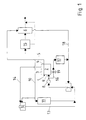
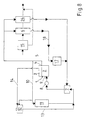
- the cooling and heating circuits shown in the figures for motor vehicles initially have an internal combustion engine 1 with a water-cooled cylinder block 2 and one as well water-cooled cylinder head 3. That in the internal combustion engine 1 circulating in the cylinder block 2 and in the cylinder head 3 Cooling water or coolant becomes a coolant outlet 4 out, on which a coolant line 5 followed.
- the coolant line leads 5 to a heating heat exchanger 6 and a thermostat 7 and a coolant pump 8 back to a coolant inlet 9 of the internal combustion engine 1.
- a heating heat exchanger 6 a counterflow heating heat exchanger is used. This shows a good one even with a low coolant throughput Efficiency.
- a coolant line 10 From the coolant line leading to the heating heat exchanger 6 5 branches a coolant line 10 to the coolant inlet a radiator heat exchanger 11, the coolant outlet is connected to the thermostat 7, through the circulation of the coolant through the radiator heat exchanger 11 can be prevented.
- the radiator heat exchanger 11 and the coolant chamber in the cylinder head 3 is an expansion tank 12 via corresponding lines 13, 14 connected.
- the heating heat exchanger 6 Controlled on the air side via a control valve 15.
- a water-side Regulation of the passenger compartment temperature is also possible.
- the internal combustion engine 1 branches off to a coolant line 16 a lubricant / coolant heat exchanger 17, which with Lubricant is supplied from the internal combustion engine 1.
- the coolant outlet of the lubricant / coolant heat exchanger is upstream of the thermostat 7 to the coolant line coming from the heating heat exchanger 6 18 connected so that a short circuit "coolant pump - Lubricant / coolant heat exchanger - coolant pump " is available.
- a closing valve 19 is arranged, the amount of the lubricant / coolant heat exchanger To control 17 flowing coolant.
- the lubricant / coolant heat exchanger 17 serves in this case to cool the coolant, d. H. to heat the lubricant, causing this reaches operating temperature faster.
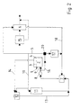
- a three-way valve 20 can be interposed.
- An inlet of the three-way valve is with the coolant pump 8 connected, while the second inlet via a branch the coolant line 5 with the coolant outlet 4 of the internal combustion engine 1 is connected.
- the outlet of the Three-way valve 20 is at the coolant inlet of the Lubricant / coolant heat exchanger 17 connected.
- the branch line 16 When using a three-way valve 20, if a maximum Passenger compartment heating is desired, the branch line 16 open, on the other hand, if heating up as quickly as possible of the lubricant is desired, the secondary line 16 is closed and the line 5 to the coolant outlet 4 of the Internal combustion engine 1 opened, causing the warm, from the Internal combustion engine 1 leaking coolant into the lubricant / coolant heat exchanger 17 occurs.
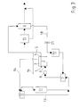
- the throttle valve 21 opened and thus the coolant flow rate set high. In this case the temperature drop of the coolant in the heating heat exchanger 6 less so that the coolant in the lubricant / coolant heat exchanger 17 heated the lubricant.
- the actuation of the throttle valve 21 can change the engine speed and the load profile with reference to FIG based on the ambient temperature. An easier one and possibly more effective way can in the Arrangement of a temperature sensor for the outflow temperature of the passenger compartment heating air. If the temperature not a given temperature limit after a given Throttle valve 21 is reached partially closed and thus the increased passenger compartment heating output activated.
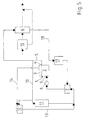
- a three-way valve 22 may be provided.
- the Coolant outlet of the heating heat exchanger 6 via a Branch 23 of the coolant line 18 with an inlet of the three-way valve 22 connected.
- the other inlet of the Three-way valve 22 is with the coolant outlet 4 of Internal combustion engine 1 connected.
- the coolant inlet of the lubricant / coolant heat exchanger 17 is connected.
- Coolant lines 18 designed from the outset for low designed for medium engine speeds, so that no special facilities for reducing the Flow rate are necessary.
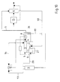
- FIGS. 3 to 5 Embodiments with the addition that parallel to the first Heater heat exchanger 6 and to the lubricant / coolant heat exchanger 17 another heating heat exchanger 24 switched is.
- the operating states of the first heating heat exchanger 6 correspond to those with reference to FIGS. 3 to 5 described.
- the flow rate for the second heater heat exchanger 24 is always set high, so the temperature accordingly of the exiting from the second heating heat exchanger 24 Coolant is high and for faster heating the internal combustion engine 1 contributes.
- Fig. 9 The embodiment shown in Fig. 9 is for the case provided that the pressure drop in the first heater core 6 is relatively low.
- a throttle valve 25 is then preferably in that of the second heating heat exchanger 24 outgoing coolant line arranged.
- the operation of the throttle valve 25 is in this case opposite to the case of FIG. 6.
- the throttle valve 25 is opened in the event of a heating deficit and partially or completely closed if there is no heating deficit is.
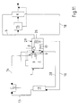
- the coolant pump 8 as a regulated pump with a variable delivery rate and at the coolant outlet 4 of the internal combustion engine 1 is arranged.
- the coolant pump 8 acts on a coolant line 5 and a bypass line 10.
- the coolant line 5 leads to a heating heat exchanger 6 and the bypass line 10 to a cooler heat exchanger 11.
- a pressure relief valve 26 turned on, only when exceeding one predetermined delivery pressure of the coolant pump 8 opens.
- a coolant line 18 leads from the heating heat exchanger 6 via a lubricant / coolant heat exchanger 17 and via a coolant line 27 to the coolant inlet 9 of the internal combustion engine 1. From the radiator heat exchanger 11 a coolant line 28 also to the coolant inlet 9 on the internal combustion engine 1.
- This embodiment can be of four different types Operating states are operated.
- coolant flows from the coolant pump 8 via the coolant line 5 to the heating heat exchanger 6 and from this back over the lubricant / coolant heat exchanger 17 to coolant inlet 9 on the internal combustion engine 1.
- Die Coolant pump 8 is relatively small Delivery pressure work so that the pressure relief valve 26 in the Bypass line 10 to the radiator heat exchanger 11 does not open. The coolant gets into the lubricant / coolant heat exchanger 17 with a lower temperature as the lubricant of the internal combustion engine 1 and takes from this heat on.
- the coolant pump 8 In an operating state in which there is no heat deficit for the Passenger compartment is present, the coolant pump 8 with operated at a higher delivery pressure, but still is less than that at which the pressure relief valve 26 open would.
- the heating heat exchanger 6 is on the control valve 15 controlled on the air side. Because the water side temperature drop with high coolant throughput in the heating heat exchanger 6 is low, the coolant in the Lubricant / coolant heat exchanger 17 the lubricant hardly any more heat.
- the coolant pump 8 With an even higher Delivery pressure operated, which leads to a faster flow of the heating heat exchanger 6 leads.
- the coolant Accordingly, it loses less heat, thereby the temperature of the coolant is higher than that of the lubricant is so that it is in the lubricant / coolant heat exchanger 17 More likely to heat the lubricant comes.
- the coolant pump 8 In an operating state in which excess heat for Is available, the coolant pump 8 is so high Delivery pressure operated that the pressure relief valve 26 opens and applied to the radiator heat exchanger 11 so that the Excess heat in the coolant is dissipated to the ambient air can be.
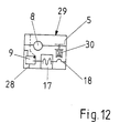
- the required ones Control components by the controllable Coolant pump 8, the pressure relief valve 26, the lubricant / coolant heat exchanger 17 and the coolant inlet 9 are formed on the internal combustion engine 1 in a heat control module 29 summarized that on the internal combustion engine 1 can be arranged.
- a thermostatic controller 30 is also added can to meet all operating conditions. In particular, direct control of the Coolant pump 8 with a variable delivery rate through a temperature sensitive Control possible.
Landscapes
- Engineering & Computer Science (AREA)
- Mechanical Engineering (AREA)
- Chemical & Material Sciences (AREA)
- Combustion & Propulsion (AREA)
- General Engineering & Computer Science (AREA)
- Physics & Mathematics (AREA)
- Thermal Sciences (AREA)
- Air-Conditioning For Vehicles (AREA)
- Lubrication Of Internal Combustion Engines (AREA)
Description
- Fig. 1
- eine schematische Darstellung einer ersten Ausführungsform eines erfindungsgemäßen Kühl- und Heizungskreislaufes, bei dem ein Schmiermittel/Kühlmittel-Wärmetauscher in einer durch ein Schließventil wegschaltbaren Nebenleitung angeordnet ist;
- Fig. 2
- eine der Fig. 1 ähnliche Darstellung einer weiteren Ausführungsform, bei der der Schmiermittel/Kühlmittel-Wärmetauscher in einer durch ein Dreiwegeventil wegschaltbaren Nebenleitung angeordnet ist;
- Fig. 3
- eine der Fig. 1 ähnliche Darstellung einer weiteren Ausführungsform, bei der zwischen Heizungs-Wärmetauscher und Schmiermittel/Kühlmittel-Wärmetauscher ein Drosselventil angeordnet ist;
- Fig. 4
- eine der Fig. 1 ähnliche Darstellung einer weiteren Ausführungsform, bei der ein Dreiwegeventil vorgesehen ist, dessen zwei Einlässe mit dem Kühlmittelaustritt des Heizungs-Wärmetauschers und dem der Brennkraftmaschine und dessen Auslaß mit dem Schmiermittel/Kühlmittel-Wärmetauscher verbunden sind;
- Fig. 5
- eine der Fig. 1 ähnliche Darstellung einer weiteren Ausführungsform, bei der die Strömungsrate des Kühlmittels durch den Heizungs-Wärmetauscher mittels der Kühlmittelleitung selbst eingestellt ist;
- Fig. 6
- bis 8 den Fig. 3 bis 5 entsprechende Ausführungsformen, wobei ein zweiter Heizungs-Wärmetauscher vorgesehen ist;
- Fig. 9
- eine der Fig. 6 ähnliche Ausführungsform, bei der statt dem ersten dem zweiten Heizungs-Wärmetauscher ein Drosselventil nachgeschaltet ist;
- Fig. 10
- eine der Fig. 1 ähnliche Darstellung einer weiteren Ausführungsform, bei der die zum Kühler-Wärmetauscher führende Leitung durch eine Kühlmittelpumpe mit variabler Fördermenge und ein Überdruckventil wegschaltbar ist;
- Fig. 11
- eine der Fig. 10 entsprechende Ausführungsform, bei der mehrere Bauteile zu einem Modul zusammengefaßt sind; und
- Fig. 12
- eine schematische Darstellung einer alternativen Ausführungsform des Überdruckventils aus den Figuren 10 und 11.
Claims (14)
- Verfahren zum Heizen eines Kraftfahrzeug-Fahrgastraumes, insbesondere bei einem Kaltstart oder bei ähnlichen Bedingungen, wobei das Kraftfahrzeug eine mit Kühlmittel gekühlte und mit Schmiermittel geschmierte Brennkraftmaschine (1) sowie einen Kühl- und Heizungskreislauf mit mindestens einem Heizungs-Wärmetauscher (6, 24) und einem Kühler-Wärmetauscher (11) aufweist, und wobei aus der Brennkraftmaschine (1) austretendes Kühlmittel in dem Heizungs-Wärmetauscher (6, 24) auf eine Temperatur abgekühlt wird, die niedriger als die des Schmiermittels ist, anschließend zumindest teilweise in einem Schmiermittel/Kühlmittel-Wärmetauscher (17) wieder erwärmt und dann, ohne den Kühler-Wärmetauscher (11) zu durchströmen, der Brennkraftmaschine (1) wieder zugeführt wird,
dadurch gekennzeichnet, daß in Betriebszuständen mit Fahrgastraum-Heizungsdefizit das gesamte aus der Brennkraftmaschine (1) austretende Kühlmittel zu dem Heizungs-Wärmetauscher (6, 24) und dann zumindest teilweise zu dem Schmiermittel/Kühlmittel-Wärmetauscher geleitet wird, ohne den Kühler-Wärmetauscher (11) zu durchströmen, und
daß in Betriebszuständen ohne Fahrgastraum-Heizungsdefizit das den Kühler-Wärmetauscher (11) durchströmende Kühlmittel zumindest teilweise der Brennkraftmaschine (1) zugeführt wird, ohne den Schmiermittel/Kühlmittel-Wärmetauscher (17) zu durchströmen. - Kühl- und Heizungskreislauf für Kraftfahrzeuge mit einer durch Kühlmittel gekühlten und durch Schmiermittel geschmierten Brennkraftmaschine (1), deren von einer Kühlmittelpumpe (8) gefördertes Kühlmittel über mindestens einen Heizungs-Wärmetauscher (6, 24) und einen Kühler-Wärmetauscher (11) zirkuliert, wobei in Strömungsrichtung hinter dem Heizungs-Wärmetauscher (6, 24) ein Schmiermittel/Kühlmittel-Wärmetauscher (17) angeordnet ist, welchem Schmiermittel aus der Brennkraftmaschine (1) zugeführt wird, und die Strömungsrate des durch den Heizungs-Wärmetauscher (6, 24) strömenden Kühlmittels soweit reduzierbar ist, daß die Kühlmittelaustrittstemperatur aus dem Heizungs-Wärmetauscher (6, 24) niedriger ist als die Schmiermitteltemperatur,
dadurch gekennzeichnet, daß der Kühler-Wärmetauscher (11) wegschaltbar ist und im nicht weggeschalteten Zustand sein Kühlmittelaustritt ohne Einbindung des Schmiermittel/Kühlmittel-Wärmetauschers (17) mit dem Kühlmitteleintritt (9) der Brennkraftmaschine (1) verbindbar ist, wobei
in Betriebszuständen mit Fahrgastraum-Heizungsdefizit das gesamte aus der Brennkraftmaschine (1) austretende Kühlmittel den Heizungs-Wärmetauscher (6, 24) und dann zumindest teilweise den Schmiermittel/Kühlmittel-Wärmetauscher (17) durchströmt, ohne den Kühler-Wärmetauscher (11) zu durchlaufen, und
in Betriebszuständen ohne Fahrgastraum-Heizungsdefizit zumindest ein Teil des den Kühler-Wärmetauscher (11) durchströmenden Kühlmittels zur Brennkraftmaschine (1) strömt, ohne den Schmiermittel/Kühlmittel-Wärmetauscher (17) zu durchlaufen. - Kühl- und Heizungskreislauf nach Anspruch 2, dadurch gekennzeichnet, daß der Heizungs-Wärmetauscher (6) in Gegenstrombauweise ausgebildet ist.
- Kühl- und Heizungskreislauf nach Anspruch 2 oder 3, dadurch gekennzeichnet, daß die Kühlmittelpumpe (8) in einer Hauptleitung (18) in Strömungsrichtung zwischen Heizungs-Wärmetauscher (6) und Brennkraftmaschine (1) angeordnet ist und zwischen Kühlmittelpumpe (8) und Brennkraftmaschine (1) eine wegschaltbare Nebenleitung (16) zum Schmiermittel/Kühlmittel-Wärmetauscher (17) abzweigt, die in Strömungsrichtung vor der Kühlmittelpumpe (8) wieder in die Hauptleitung (18) einmündet.
- Kühl- und Heizungskreislauf nach Anspruch 4, dadurch gekennzeichnet, daß die Nebenleitung (16) durch ein in Strömungsrichtung vor dem Schmiermittel/Kühlmittel-Wärmetauscher (17) angeordnetes Schließventil (19) wegschaltbar ist.
- Kühl- und Heizungskreislauf nach Anspruch 4, dadurch gekennzeichnet, daß die Nebenleitung (16) durch ein in Strömungsrichtung vor dem Schmiermittel/Kühlmittel-Wärmetauscher (17) angeordnetes Dreiwegeventil (20) wegschaltbar ist, dessen dritter Anschluß mit dem Kühlmittelaustritt (4) der Brennkraftmaschine (1) verbunden ist.
- Kühl- und Heizungskreislauf nach Anspruch 2 oder 3, dadurch gekennzeichnet, daß der den Heizungs-Wärmetauscher (6) und den Schmiermittel/Kühlmittel-Wärmetauscher (17) enthaltende Kreislauf (5, 18) für eine auf niedrige bis mittlere Brennkraftmaschinen-Drehzahlen bezogene Kühlmittel-Strömungsrate ausgelegt ist.
- Kühl- und Heizungskreislauf nach Anspruch 2 oder 3, dadurch gekennzeichnet, daß zwischen Heizungs-Wärmetauscher (6) und Schmiermittel/Kühlmittel-Wärmetauscher (17) ein Drosselventil (21) angeordnet ist.
- Kühl- und Heizungskreislauf nach Anspruch 2 oder 3, dadurch gekennzeichnet, daß der Kühlmittelaustritt des Heizungs-Wärmetauschers (6) über eine Verzweigung einerseits mit dem Kühlmitteleintritt des Schmiermittel/Kühlmittel-Wärmetauschers (17) und andererseits mit dem Kühlmitteleintritt (9) der Brennkraftmaschine (1) verbunden ist, wobei zur Verbindung des Heizungs-Wärmetauschers (6) mit dem Schmiermittel/Kühlmittel-Wärmetauscher (17) ein Dreiwegeventil (22) vorgesehen ist, dessen zweiter Einlaß mit dem Kühlmittelaustritt (4) der Brennkraftmaschine (1) verbunden ist.
- Kühl- und Heizungskreislauf nach einem der Ansprüche 7 bis 9, dadurch gekennzeichnet, daß ein zweiter Heizungs-Wärmetauscher (24) parallel zum ersten Heizungs-Wärmetauscher (6) und zum Schmiermittel/Kühlmittel-Wärmetauscher (17) geschaltet und die Strömungsrate des Kühlmittels durch den zweiten Heizungs-Wärmetauscher (24) größer als die durch den ersten Heizungs-Wärmetauscher (6) ist.
- Kühl- und Heizungskreislauf nach Anspruch 2 oder 3, dadurch gekennzeichnet, daß ein zweiter Heizungs-Wärmetauscher (24) parallel zum ersten Heizungs-Wärmetauscher (6) und zum Schmiermittel/Kühlmittel-Wärmetauscher (17) geschaltet ist und die Strömungsrate des den zweiten Heizungs-Wärmetauscher (24) durchströmenden Kühlmittels einstellbar ist.
- Kühl- und Heizungskreislauf nach Anspruch 2, dadurch gekennzeichnet, daß eine Kühlmittelpumpe (8) mit variabler Fördermenge in Strömungsrichtung vor einer Verzweigung der Kühlmittelleitung (5) zu einerseits dem Heizungs-Wärmetauscher (6) und zu andererseits einer Bypassleitung (10) zu dem Kühler-Wärmetauscher (11) angeordnet ist, und daß in der Bypassleitung (10) ein Überdruckventil (26) vorgesehen ist, das nur bei Überschreiten eines vorgegebenen Förderdruckes Kühlmittel unmittelbar zum Kühler-Wärmetauscher (11) und von dort zurück zu einem Kühlmitteleintritt (9) an der Brennkraftmaschine (1) führt.
- Kühl- und Heizungskreislauf nach Anspruch 12, dadurch gekennzeichnet, daß das Überdruckventil (26) ein thermostatisch gesteuertes Überdruckventil ist.
- Kühl- und Heizungskreislauf nach Anspruch 12 oder 13, jeweils in Verbindung mit einem der Ansprüche 2 bis 11, dadurch gekennzeichnet, daß bei einer Brennkraftmaschine (1), deren Kühlmittelauslaß und deren Kühlmitteleinlaß zueinander benachbart angeordnet sind, die für die Wärme-Steuerung erforderlichen Bauteile, wie die variable Kühlmittelpumpe (8), die Bypassleitung (10) mit dem Überdruckventil (26), der Schmiermittel/Kühlmittel-Wärmetauscher (17) und der Kühlmitteleintritt (9) in einem Wärme-Steuerungsmodul (29) zusammengefaßt sind, das an die Brennkraftmaschine (1) im Bereich deren Kühlmittelauslasses und -einlasses anfügbar ist.
Priority Applications (2)
| Application Number | Priority Date | Filing Date | Title |
|---|---|---|---|
| EP98109504A EP0960759B1 (de) | 1998-05-26 | 1998-05-26 | Heizung für einen Kraftfahrzeug-Fahrgastraum |
| DE59803065T DE59803065D1 (de) | 1998-05-26 | 1998-05-26 | Heizung für einen Kraftfahrzeug-Fahrgastraum |
Applications Claiming Priority (1)
| Application Number | Priority Date | Filing Date | Title |
|---|---|---|---|
| EP98109504A EP0960759B1 (de) | 1998-05-26 | 1998-05-26 | Heizung für einen Kraftfahrzeug-Fahrgastraum |
Publications (2)
| Publication Number | Publication Date |
|---|---|
| EP0960759A1 EP0960759A1 (de) | 1999-12-01 |
| EP0960759B1 true EP0960759B1 (de) | 2002-02-13 |
Family
ID=8232002
Family Applications (1)
| Application Number | Title | Priority Date | Filing Date |
|---|---|---|---|
| EP98109504A Expired - Lifetime EP0960759B1 (de) | 1998-05-26 | 1998-05-26 | Heizung für einen Kraftfahrzeug-Fahrgastraum |
Country Status (2)
| Country | Link |
|---|---|
| EP (1) | EP0960759B1 (de) |
| DE (1) | DE59803065D1 (de) |
Families Citing this family (4)
| Publication number | Priority date | Publication date | Assignee | Title |
|---|---|---|---|---|
| GB0220521D0 (en) | 2002-09-04 | 2002-10-09 | Ford Global Tech Inc | A motor vehicle and a thermostatically controlled valve therefor |
| FR2846715B1 (fr) * | 2002-11-04 | 2006-06-23 | Valeo Climatisation | Dispositif d'apport calorifique a une boucle de refroidissement d'un moteur de vehicule automobile |
| DE102005063707B4 (de) | 2005-07-23 | 2026-08-20 | Att Automotivethermotech Gmbh | Verfahren und Vorrichtung zur verbesserten Nutzung der Motorabwärme bei Kraftfahrzeugen mit und ohne Betrieb der Kabinenbeheizung |
| DE102005063692B4 (de) * | 2005-07-23 | 2025-05-28 | Att Automotivethermotech Gmbh | Vorrichtungen zur Kraftstoffeinsparung bei Kraftfahrzeugen mit und ohne Betrieb der Kabinenheizung |
Family Cites Families (7)
| Publication number | Priority date | Publication date | Assignee | Title |
|---|---|---|---|---|
| DE3118167A1 (de) * | 1981-05-08 | 1982-11-25 | Klöckner-Humboldt-Deutz AG, 5000 Köln | Heizeinrichtung |
| FR2571431B1 (fr) * | 1984-10-09 | 1989-04-21 | Renault Vehicules Ind | Dispositif de refroidissement pour moteur a combustion interne |
| JPH061136A (ja) * | 1992-06-19 | 1994-01-11 | Toyota Autom Loom Works Ltd | 車両用空調装置 |
| US5419287A (en) * | 1992-09-18 | 1995-05-30 | Evans; John W. | Engine cooling system and heater circuit therefor |
| JPH07228132A (ja) | 1994-02-18 | 1995-08-29 | Toyota Autom Loom Works Ltd | 車両用暖房装置 |
| DE19508102C1 (de) | 1995-03-08 | 1996-07-25 | Volkswagen Ag | Verfahren zur Regelung eines Kühlkreislaufes eines Verbrennungskraftmotors, insbesondere für Kraftfahrzeuge |
| JPH0979020A (ja) | 1995-09-12 | 1997-03-25 | Ngk Spark Plug Co Ltd | 内燃機関用の潤滑油加熱装置及びその潤滑油の適温保持方法 |
-
1998
- 1998-05-26 EP EP98109504A patent/EP0960759B1/de not_active Expired - Lifetime
- 1998-05-26 DE DE59803065T patent/DE59803065D1/de not_active Expired - Lifetime
Also Published As
| Publication number | Publication date |
|---|---|
| DE59803065D1 (de) | 2002-03-21 |
| EP0960759A1 (de) | 1999-12-01 |
Similar Documents
| Publication | Publication Date | Title |
|---|---|---|
| DE3433370C2 (de) | ||
| EP1947308B1 (de) | Integriertes Motorkühlsystem | |
| DE19608748B4 (de) | Kühlwasser-Umwälzsystem für den Verbrennungsmotor eines Fahrzeugs | |
| DE19954327B4 (de) | Verfahren und Vorrichtung zum Transport von in einem Kraftfahrzeug entstehender Wärmeenergie | |
| DE102014215074B4 (de) | Temperieranordnung für Getriebeöl eines Kraftfahrzeugs sowie Verfahren zum Temperieren von Getriebeöl eines Kraftfahrzeugs | |
| EP1319815A2 (de) | Kühlkreislauf einer flüssigkeitsgekühlten Brennkraftmaschine | |
| DE102011053591A1 (de) | Vorrichtung zur Wiedergewinnung und Kühlung von Abwärme für einen Motor | |
| EP4171977B1 (de) | Thermomanagementsystem für ein elektrofahrzeug und verfahren zu dessen betrieb | |
| EP1108572B1 (de) | Wärmetauschsystem für die Heizung eines Fahrzeugs mit Hybridantrieb | |
| DE10332949A1 (de) | Vorrichtung zum Kühlen und Vorwärmen | |
| EP1923549B1 (de) | Kühlsystem für ein Kraftfahrzeug | |
| WO2014177513A1 (de) | Kühlkreislauf | |
| DE10146313A1 (de) | Kühlkreislauf einer flüssigkeitsgekühlten Brennkraftmaschine | |
| EP3530899A1 (de) | Kühlsystem und brennkraftmaschine | |
| DE10319762A1 (de) | Kreislauf zur Kühlung von Ladeluft und Verfahren zum Betreiben eines derartigen Kreislaufs | |
| DE112018004425T5 (de) | Aktives Aufheizsystem und Aufheizverfahren | |
| DE10301448A1 (de) | Vorrichtung zur Temperierung von Schmieröl eines Kraftfahrzeugs | |
| DE10047081B4 (de) | Verfahren und Vorrichtung zur Kühlung einer Brennkraftmaschine | |
| DE102004061426A1 (de) | System und Verfahren zum Temperieren eines Motoröls einer Brennkraftmaschine eines Kraftfahrzeugs | |
| DE10302170A1 (de) | Kühlmittelkreislauf für eine Brennkraftmaschine | |
| DE4131357C1 (en) | IC engine cooling installation with engine-driven pump - has electrically driven second pump with external line contg. two thermostatic valves | |
| EP0960759A1 (de) | Heizung für einen Kraftfahrzeug-Fahrgastraum | |
| EP1536961B1 (de) | System und verfahren zur regulierung des wärmehaushalts eines fahrzeugs | |
| DE10143109B4 (de) | Verfahren und Vorrichtung zur Einstellung definierter Kühlmittelströme in Kühlsystemen von Brennkraftmaschinen in Kraftfahrzeugen | |
| DE102012019091A1 (de) | Kurbelgehäuse für eine Verbrennungskraftmaschine sowie Verbrennungskraftmaschine mit einem solchen Kurbelgehäuse |
Legal Events
| Date | Code | Title | Description |
|---|---|---|---|
| PUAI | Public reference made under article 153(3) epc to a published international application that has entered the european phase |
Free format text: ORIGINAL CODE: 0009012 |
|
| 17P | Request for examination filed |
Effective date: 19981221 |
|
| AK | Designated contracting states |
Kind code of ref document: A1 Designated state(s): DE FR GB |
|
| AX | Request for extension of the european patent |
Free format text: AL;LT;LV;MK;RO;SI |
|
| 17Q | First examination report despatched |
Effective date: 20000404 |
|
| AKX | Designation fees paid |
Free format text: DE FR GB |
|
| GRAG | Despatch of communication of intention to grant |
Free format text: ORIGINAL CODE: EPIDOS AGRA |
|
| GRAG | Despatch of communication of intention to grant |
Free format text: ORIGINAL CODE: EPIDOS AGRA |
|
| GRAH | Despatch of communication of intention to grant a patent |
Free format text: ORIGINAL CODE: EPIDOS IGRA |
|
| GRAH | Despatch of communication of intention to grant a patent |
Free format text: ORIGINAL CODE: EPIDOS IGRA |
|
| GRAA | (expected) grant |
Free format text: ORIGINAL CODE: 0009210 |
|
| REG | Reference to a national code |
Ref country code: GB Ref legal event code: IF02 |
|
| AK | Designated contracting states |
Kind code of ref document: B1 Designated state(s): DE FR GB |
|
| REF | Corresponds to: |
Ref document number: 59803065 Country of ref document: DE Date of ref document: 20020321 |
|
| GBT | Gb: translation of ep patent filed (gb section 77(6)(a)/1977) |
Effective date: 20020417 |
|
| ET | Fr: translation filed | ||
| PLBE | No opposition filed within time limit |
Free format text: ORIGINAL CODE: 0009261 |
|
| STAA | Information on the status of an ep patent application or granted ep patent |
Free format text: STATUS: NO OPPOSITION FILED WITHIN TIME LIMIT |
|
| 26N | No opposition filed |
Effective date: 20021114 |
|
| REG | Reference to a national code |
Ref country code: GB Ref legal event code: 732E |
|
| REG | Reference to a national code |
Ref country code: FR Ref legal event code: TP |
|
| REG | Reference to a national code |
Ref country code: GB Ref legal event code: 746 Effective date: 20060405 |
|
| PGFP | Annual fee paid to national office [announced via postgrant information from national office to epo] |
Ref country code: DE Payment date: 20120531 Year of fee payment: 15 |
|
| PGFP | Annual fee paid to national office [announced via postgrant information from national office to epo] |
Ref country code: GB Payment date: 20120426 Year of fee payment: 15 Ref country code: FR Payment date: 20120510 Year of fee payment: 15 |
|
| GBPC | Gb: european patent ceased through non-payment of renewal fee |
Effective date: 20130526 |
|
| PG25 | Lapsed in a contracting state [announced via postgrant information from national office to epo] |
Ref country code: DE Free format text: LAPSE BECAUSE OF NON-PAYMENT OF DUE FEES Effective date: 20131203 |
|
| REG | Reference to a national code |
Ref country code: DE Ref legal event code: R119 Ref document number: 59803065 Country of ref document: DE Effective date: 20131203 |
|
| REG | Reference to a national code |
Ref country code: FR Ref legal event code: ST Effective date: 20140131 |
|
| PG25 | Lapsed in a contracting state [announced via postgrant information from national office to epo] |
Ref country code: GB Free format text: LAPSE BECAUSE OF NON-PAYMENT OF DUE FEES Effective date: 20130526 |
|
| PG25 | Lapsed in a contracting state [announced via postgrant information from national office to epo] |
Ref country code: FR Free format text: LAPSE BECAUSE OF NON-PAYMENT OF DUE FEES Effective date: 20130531 |