EP0960766B1 - Kraftfahrzeugsitz mit einer elektrisch betägtigten Beinstütze - Google Patents
Kraftfahrzeugsitz mit einer elektrisch betägtigten Beinstütze Download PDFInfo
- Publication number
- EP0960766B1 EP0960766B1 EP99304193A EP99304193A EP0960766B1 EP 0960766 B1 EP0960766 B1 EP 0960766B1 EP 99304193 A EP99304193 A EP 99304193A EP 99304193 A EP99304193 A EP 99304193A EP 0960766 B1 EP0960766 B1 EP 0960766B1
- Authority
- EP
- European Patent Office
- Prior art keywords
- frame
- pivotally connected
- bridge portion
- base structure
- pbs
- Prior art date
- Legal status (The legal status is an assumption and is not a legal conclusion. Google has not performed a legal analysis and makes no representation as to the accuracy of the status listed.)
- Expired - Lifetime
Links
- 230000007246 mechanism Effects 0.000 claims description 17
- 230000009467 reduction Effects 0.000 claims description 4
- 230000004044 response Effects 0.000 description 4
- 238000010276 construction Methods 0.000 description 1
- 238000006073 displacement reaction Methods 0.000 description 1
- 230000004048 modification Effects 0.000 description 1
- 238000012986 modification Methods 0.000 description 1
Images


Classifications
-
- B—PERFORMING OPERATIONS; TRANSPORTING
- B60—VEHICLES IN GENERAL
- B60N—SEATS SPECIALLY ADAPTED FOR VEHICLES; VEHICLE PASSENGER ACCOMMODATION NOT OTHERWISE PROVIDED FOR
- B60N2/00—Seats specially adapted for vehicles; Arrangement or mounting of seats in vehicles
- B60N2/90—Details or parts not otherwise provided for
- B60N2/995—Lower-leg-rests, e.g. calf-rests
Definitions
- the present invention relates in general to automotive seats. More specifically, the present invention relates to an automotive seat having a leg-rest or footstool (referred to as an ottoman) that is moved by an electric actuator between an in-use or projected position and a non-use or retracted position.
- a leg-rest or footstool referred to as an ottoman
- the present invention provides an electrically actuated ottoman which, when assuming a projected position, becomes large in size to provide a seat occupant with a larger foot supporting area, and when assuming a retracted position, becomes compact in size to provide the seat occupant with a larger foot space of the vehicle cabin.
- US 5, 507, 562 describes a known extensible foot rest for a seat for use with a van, motor home or other motor vehicle, and discloses the features of the preamble of claim 1.
- an automotive seat according to claim 1.
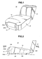
- FIGs. 1 and 2 of the drawings there is shown an automotive seat 10 equipped with an ottoman 12, which is an embodiment of the present invention.
- the automotive seat 10 comprises generally a seat cushion 14 mounted on a vehicle floor VF (see Fig. 2 ) through a seat slider SS , a seatback 16 pivotally mounted on a rear portion of the seat cushion 14 though a reclining mechanism RM and the ottoman 12 pivotally connected to a front portion of the seat cushion 14.
- the ottoman 12 is arranged to move between a projected position wherein, as is seen from Fig. 5 , the ottoman 12 is projected forward from the seat cushion 14 for allowing the seat occupant to put his lower leg thereon and a retracted position wherein, as is seen from Figs. 1, 2 , and 4 , the ottoman 12 is neatly received in a recess 14a formed in the front portion of the seat cushion 14.
- the seat cushion 14 comprises a rectangular frame 18 (only front part of which is shown). Although not shown in the drawing, springs, cushion pads and an outer skin member are incorporated with the rectangular frame 18 to constitute the seat cushion 14.
- the rectangular frame 18 is mounted on sliding rails of the seat slider SS .
- a so-called position stopper (not shown) is associated with the slider SS to lock the seat cushion 14 at a desired fore-and-aft position.
- a height adjuster (not shown) may be arranged between the rectangular frame 18 and the seat slider SS to adjust the height of the seat cushion 14.
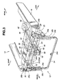
- the ottoman 12 comprises two brackets 20 and 22 which are fixed to front lateral ends of the rectangular frame 18, each being projected forward, as shown.
- Each bracket 20 or 22 has first and second links 24a and 24b or 26a and 26b which have lower ends pivotally connected to the bracket 20 or 22.
- the first and second links 24a and 24b or 26a and 26b have substantially equal length.
- Upper ends of the first and second links 24a and 24b or 26a and 26b are pivotally connected to an L-shaped bracket 28 or 30.
- These L-shaped brackets 28 and 30 are secured to lateral ends of a generally U-shaped supporting frame 32.
- the U-shaped supporting frame 32 comprises a laterally extending bridge portion 32a and right and left channel arm portions 32b and 32c each extending at generally right angles from one end of the bridge portion 32a. It is to be noted that each L-shaped bracket 28 or 30 is secured to the junction between the bridge portion 32a and the channel arm portion 32b or 32c. Thus, the U-shaped supporting frame 32 is pivotally supported by the two brackets 20 and 22 through the two pairs of pivotal links 24a, 24b, 26a, and 26b.
- the second links 24b and 26b stand substantially vertical causing the ottoman 12 to incline about 60 degrees relative to the horizontal line, as is seen from Fig. 4 .
- the distance between the upper pivoted ends of the first and second links 24a and 24b or 26a and 26b is determined smaller than the distance between the lower pivoted ends of the first and second links 24a and 24b or 26a and 26b .
- the U-shaped supporting frame 32 slidably supports a generally rectangular sliding frame 34.
- the rectangular sliding frame 34 comprises a laterally extending front bridge portion 34a, right and left rod portions 34b and 34c and a laterally extending rear bridge portion 34d.
- the right and left rod portions 34b and 34c of the rectangular sliding frame 34 are slidably received in the right and left channel arm portions 32b and 32c of the U-shaped supporting frame 32.
- the rectangular sliding frame 34 can slide relative to the U-shaped supporting frame 32 between a retracted position as shown in Fig. 4 and a projected position as shown in Fig. 5 .
- the supporting frame 32 is equipped with cushion pads and an outer skin member (no numeral) to constitute a pivotal base structure PBS
- the sliding frame 34 is equipped with cushion pads and an outer skin member (no numeral) to constitute a sliding board structure SBS.
- a bracket 36 is secured to a lower surface of a front bridge portion of the rectangular frame 18.
- An elongate case 38 is secured to the bracket 36 and extends obliquely relative to the seat slider SS.
- Within the elongate case 38 there is installed a driving mechanism for driving the ottoman 12.
- the driving mechanism comprises an electric motor 40, a speed reduction gear 42 operatively connected to an output shaft of the electric motor 40, and an elongate threaded shaft 44 connected at its rear end to an output shaft 42a of the speed reduction gear 42.
- the threaded shaft 44 is of a double spiral type.
- a front end of the threaded shaft 44 is rotatably supported by a front end portion of the elongate case 38 through a bearing member.
- a nut member 46 is operatively engaged with the elongate threaded shaft 44. From the nut member 46, there extend forward two link members 48 and 50. As is seen from Fig. 3 , the two link members 48 and 50 are pivotally connected at their front ends to a pivot member 52. The pivot member 52 is pivotally connected to a middle portion of the rear bridge portion 34d of the rectangular sliding frame 34. As will be seen from Fig. 4 , when the ottoman 12 assumes the retracted position, the pivot member 52 extends in parallel with the right and left rod portions 34b and 34c of the rectangular sliding frame 34.
- the bridge portion 32a of the U-shaped supporting frame 32 is provided at its lower surface with a supporting bracket 54 to which the two link members 48 and 50 are pivotally connected through a pivot pin 56.
- the nut member 46 takes a deeper position of the threaded shaft 44 near the speed reduction gear 42, so that the two link members 48 and 50 pull the ottoman 12 to the retracted position, that is, into the recess 14a of the seat cushion 14.
- the ottoman 12 is kept inclined about 60 degrees relative to the horizontal line.
- the sliding board structure SBS is fully received by the pivotal base structure PBS . More specifically, an extended cover portion "sbs" of the sliding board structure SBS is fully received in a recessed portion "pbs" formed on the pivotal base structure PBS .
- the electric motor 40 When now the electric motor 40 is energized to run in a first direction, the threaded shaft 44 is rotated about its axis in a so-called ottoman projecting direction. With this, the nut member 46 is forced to run forward on the threaded shaft 44 pushing the ottoman 12 through the two link members 48 and 50 and the supporting bracket 54. In response to the forward movement of the two link members 48 and 50, the ottoman 12 is moved forward while being raised, as is seen from Fig. 5 .
- first and second links 24a and 24b are pivoted forward about the pivoted lower ends thereof and the locus L2 described by the pivoted upper end of the second link 24b (or 26b) goes across the locus L1 described by the pivoted upper end of the first link 24a (or 26a).
- the sliding board structure SBS is gradually moved away from the pivotal base structure PBS increasing the foot placing area of the ottoman 12.
- a position sensor (not shown) senses the reach of the nut member 46 and stops the energization of the electric motor 40. Upon this, the ottoman 12 stops its projecting movement and keeps the projected position thereof.
- the threaded shaft44 When now the electric motor 40 is energized to run in a second direction, the threaded shaft44 is rotated about its axis in a so-called ottoman retracting direction. With this, the nut member 46 is forced to run rearward on the threaded shaft 44 pulling the ottoman 12 through the two link members 48 and 50 and th supporting bracket 54. In response to the rearward movement of the two link members 48 and 50, the ottoman 12 is moved rearward while being retracted, as is seen from Fig. 4 .
- first and second links 24a and 24b are pivoted rearward about the pivoted lower ends thereof and the locus L1 described by the pivoted upper end of the first link 24a (or 26a) goes across the locus L2 described by the pivoted upper end of the second link 24b (or 26b).
- the sliding board structure SBS is gradually moved toward the pivotal base structure PBS reducing the foot placing area of the ottoman 12.
- the foot supporting area defined by the ottoman 12 is increased, which provides a seat occupant with comfortable foot supporting.
- the foot space defined in front of the seat is not so limited.
- the sliding board structure SBS is compactly combined with the pivotal base structure PBS, which promotes the compact retraction of the ottoman 12.
Landscapes
- Engineering & Computer Science (AREA)
- Aviation & Aerospace Engineering (AREA)
- Transportation (AREA)
- Mechanical Engineering (AREA)
- Passenger Equipment (AREA)
- Seats For Vehicles (AREA)
Claims (9)
- Automobilsitz, der Folgendes umfasst:ein Sitzkissen (14), das einen Rahmen (18) einschließt, undeine Beinstütze (12), die Folgendes einschließt:eine Schwenkbasisstruktur (PBS, 32), die schwenkbar mit dem Rahmen (18) verbunden ist, wobei die Schwenkbasisstruktur bewegt werden kann zwischen einer eingezogenen Stellung, in der sie nahe dem Rahmen (18) angeordnet ist, und einer ausgefahrenen Stellung, in der sie entfernt von dem Rahmen (18) angeordnet ist, gekennzeichnet durch:eine Gleitplattenstruktur (SBS, 34), die verschiebbar durch die Schwenkbasisstruktur (PBS, 32) getragen wird, wobei die Gleitplattenstruktur bewegt werden kann zwischen einer eingezogenen Stellung, in der sie kompakt an der Schwenkbasisstruktur angebracht ist, und einer ausgefahrenen Stellung, in der sie entfernt von der Schwenkbasisstruktur angeordnet ist, undeinen elektrischen Antriebsmechanismus (40, 42, 44, 46, 48, 50, 52) zum synchronen Bewegen sowohl der Schwenkbasisstruktur (PBS, 32) als auch der Gleitplattenstruktur (SBS, 34) zwischen den eingezogenen und den ausgefahrenen Stellungen mit Hilfe von Elektroenergie.
- Automobilsitz nach Anspruch 1, wobei das Sitzkissen (14) mit einer Aussparung (14a) versehen ist, in der die Schwenkbasisstruktur (PBS, 32) sauber aufgenommen wird, wenn sie die eingezogene Stellung einnimmt.
- Automobilsitz nach Anspruch 1 oder 2, wobei die Schwenkbasisstruktur (PBS, 32) schwenkbar mit dem Rahmen (18) verbunden ist durch ein Paar von Doppellenker-Schwenkmechanismen, die jeweils Folgendes umfassen:eine erste Stütze (20; 22), die an dem Rahmen (18) befestigt ist,eine zweite Stütze (28; 30), die an der Schwenkbasisstruktur (PBS, 32) befestigt ist,einen ersten Lenker (24a; 26a), der ein oberes und ein unteres Ende hat, die schwenkbar mit der zweiten bzw. der ersten Stütze verbunden sind, undeinen zweiten Lenker (24b; 26b), der ein oberes und ein unteres Ende hat, die schwenkbar mit der zweiten bzw. der ersten Stütze verbunden sind.
- Automobilsitz nach Anspruch 3, wobei der Abstand zwischen den schwenkbaren oberen Enden des ersten und des zweiten Lenkers kleiner ist als zwischen den schwenkbaren unteren Enden des ersten und des zweiten Lenkers.
- Automobilsitz nach Anspruch 3 oder 4, wobei der elektrische Antriebsmechanismus Folgendes umfasst:einen länglichen Gewindeschaft (44), der durch den Rahmen (18) drehbar getragen und durch einen Elektromotor (40) angetrieben wird,ein Mutternelement (46), das wirksam mit dem Gewindeschaft (44) in Eingriff steht,ein Verknüpfungselement (48, 50), das sich von dem Mutternelement (46) aus erstreckt,eine erste Schwenkstruktur (54, 56), durch die das Verknüpfungselement (48; 50) schwenkbar mit der Schwenkbasisstruktur (PBS, 32) verbunden ist, undeine zweite Schwenkstruktur (52), durch die das Verknüpfungselement (48; 50) schwenkbar mit der Gleitplattenstruktur (SBS, 34) verbunden ist.
- Automobilsitz nach Anspruch 5, wobei der elektrische Antriebsmechanismus ferner ein Untersetzungsgetriebe (42) umfasst, durch das eine Abtriebswelle des Elektromotors (40) und der Gewindeschaft (44) verbunden sind.
- Automobilsitz nach Anspruch 5 oder 6, wobei die erste Schwenkstruktur einen Stützträger (54), der an der Schwenkbasisstruktur (PBS, 32) befestigt ist, und einen Drehzapfen (56), durch den das Verknüpfungselement (48; 50) schwenkbar mit dem Stützträger (54) verbunden ist, umfasst und wobei die zweite Schwenkstruktur ein Schwenkelement (52) umfasst, dessen eines Ende schwenkbar mit der Gleitplattenstruktur (SBS, 34) verbunden ist und dessen anderes Ende schwenkbar mit einem vorderen Ende des Verknüpfungselement (48; 50) verbunden ist.
- Automobilsitz nach einem der vorhergehenden Ansprüche, wobei die Schwenkbasisstruktur (PBS) einen im Allgemeinen U-förmigen Stützrahmen (32) umfasst, der einen sich seitlich erstreckenden Brückenabschnitt (32a) und einen rechten und einen linken Kanalarmabschnitt (32b, 32c), die sich im Allgemeinen im rechten Winkel von beiden Enden des Brückenabschnitts aus erstrecken, einschließt, und wobei die Gleitplattenstruktur (SBS) einen im Allgemeinen rechteckigen Gleitrahmen (34) umfasst, der einen sich seitlich erstreckenden vorderen Brückenabschnitt (34a), einen rechten und einen linken Stangenabschnitt (34b, 34c) und einen sich seitlich erstreckenden hinteren Brückenabschnitt (34d) einschließt, wobei die Stangenabschnitte (34b, 34c) verschiebbar in den jeweiligen Kanalarmabschnitten (32b, 32c) aufgenommen werden.
- Automobilsitz nach Anspruch 1, wobei:die schwenkbare Basisstruktur einen im Allgemeinen U-förmigen Stützrahmen (32) umfasst, der einen sich seitlich erstreckenden Brückenabschnitt (32a) und einen rechten und einen linken Kanalarmabschnitt (32b, 32c), die sich im Allgemeinen im rechten Winkel von beiden Enden des Brückenabschnitts (32a) aus erstrecken, einschließt,die Gleitplattenstruktur einen im Allgemeinen rechteckigen Gleitrahmen (34) umfasst, der einen sich seitlich erstreckenden vorderen Brückenabschnitt (34a), einen rechten und einen linken Stangenabschnitt (34b, 34c) und einen sich seitlich erstreckenden hinteren Brückenabschnitt (34d) einschließt, wobei die Stangenabschnitte (34b, 34c) verschiebbar in den jeweiligen Kanalarmabschnitten (32b, 32c) aufgenommen werden, undder elektrische Antriebsmechanismus Folgendes umfasst:wobei das System ferner Folgendes umfasst:einen länglichen Gewindeschaft (44), der durch einen Elektromotor (40) angetrieben wird, um sich um seine Achse zu drehen,Mittel zum Unterdrücken der Axialbewegung des Gewindeschafts (44), während seine Drehung gestattet ist,ein Mutternelement (46), das wirksam mit dem Gewindeschaft (44) in Eingriff steht, undein Verknüpfungselement (48, 50), das sich von dem Mutternelement (46) aus erstreckt,ein Paar von Doppellenker-Schwenkmechanismen (24a, 24b; 26a, 26b), durch die der Brückenabschnitt (32a) schwenkbar mit dem Sitzkissenrahmen (18) verbunden ist,eine erste Schwenkstruktur (54, 56), durch die das Verknüpfungselement (48; 50) schwenkbar mit dem Brückenabschnitt (32a) des Stützrahmens (32) verbunden ist, undeine zweite Schwenkstruktur (52), durch die das Verknüpfungselement (48; 50) schwenkbar mit dem hinteren Brückenabschnitt (34d) des Gleitrahmens verbunden ist.
Applications Claiming Priority (2)
| Application Number | Priority Date | Filing Date | Title |
|---|---|---|---|
| JP16430498 | 1998-05-28 | ||
| JP16430498A JP3323989B2 (ja) | 1998-05-28 | 1998-05-28 | 電動オットマン装置 |
Publications (3)
| Publication Number | Publication Date |
|---|---|
| EP0960766A2 EP0960766A2 (de) | 1999-12-01 |
| EP0960766A3 EP0960766A3 (de) | 2001-02-21 |
| EP0960766B1 true EP0960766B1 (de) | 2009-01-07 |
Family
ID=15790589
Family Applications (1)
| Application Number | Title | Priority Date | Filing Date |
|---|---|---|---|
| EP99304193A Expired - Lifetime EP0960766B1 (de) | 1998-05-28 | 1999-05-28 | Kraftfahrzeugsitz mit einer elektrisch betägtigten Beinstütze |
Country Status (3)
| Country | Link |
|---|---|
| US (1) | US6095610A (de) |
| EP (1) | EP0960766B1 (de) |
| JP (1) | JP3323989B2 (de) |
Cited By (1)
| Publication number | Priority date | Publication date | Assignee | Title |
|---|---|---|---|---|
| CN102991383A (zh) * | 2012-10-29 | 2013-03-27 | 天津博信汽车零部件有限公司 | 一种便于拆装的多功能汽车座椅调节手柄 |
Families Citing this family (75)
| Publication number | Priority date | Publication date | Assignee | Title |
|---|---|---|---|---|
| JP3323989B2 (ja) * | 1998-05-28 | 2002-09-09 | ジョンソン コントロールズ オートモーティブ システムズ株式会社 | 電動オットマン装置 |
| EP1116653B1 (de) * | 2000-01-14 | 2006-03-15 | Be Aerospace, Inc. | Fahrgastsitz mit Fussstütze aus Stoff |
| DE10003407A1 (de) * | 2000-01-27 | 2001-08-09 | Recaro Aircraft Seating Gmbh | Fahrzeugsitz für Flug-oder Kraftfahrzeuge |
| IT1318407B1 (it) * | 2000-03-17 | 2003-08-25 | C I A R S R L Ora C I A R S P | Pediera estensibile, particolarmente per poltrone, divani e simili. |
| FR2806674B1 (fr) * | 2000-03-24 | 2002-09-27 | Labinal | Procede de gestion du fonctionnement d'un siege et siege mettant en oeuvre ce procede |
| JP2001292860A (ja) * | 2000-04-17 | 2001-10-23 | Johnson Controls Automotive Systems Corp | 電動オットマン装置 |
| US20010048239A1 (en) * | 2000-04-17 | 2001-12-06 | Masaaki Kogure | Motor-driven footrest device of seat |
| US6758520B2 (en) * | 2001-01-05 | 2004-07-06 | Ford Global Technologies, Inc. | Adjustable height automotive seat |
| JP2002240616A (ja) * | 2001-02-15 | 2002-08-28 | Minebea Co Ltd | 乗物用シートのフットレスト装置 |
| DE10107195A1 (de) * | 2001-02-16 | 2002-09-12 | Recaro Aircraft Seating Gmbh | Fahrzeugsitz, insbesondere Fluggastsitz |
| JP2002248971A (ja) * | 2001-02-22 | 2002-09-03 | Minebea Co Ltd | 電動座席 |
| CA2359985A1 (en) * | 2001-10-12 | 2003-04-12 | Viet Pham | Low profile articulated footrests unit and glider armchair using same |
| US7427102B2 (en) * | 2002-02-08 | 2008-09-23 | Recaro Aircraft Seating Gmbh & Co. | Vehicle seat with seating components adjustable within a spatial constraint |
| DE10209234B4 (de) * | 2002-03-04 | 2005-06-09 | Daimlerchrysler Ag | Fahrzeugsitz mit Unterschenkelstütze |
| DE10314709A1 (de) * | 2002-04-07 | 2003-11-20 | Erker Christian | Mechanismus zur Umlenkung von Stützflächen |
| US6698836B1 (en) * | 2002-08-26 | 2004-03-02 | Aviointeriors S.P.A. | Mechanism to obtain the complete reclining of a seat, particularly for an aircraft seat |
| BE1015145A4 (nl) * | 2002-10-14 | 2004-10-05 | De Vroe Nv | Mechanisme voor het uitklappen en uitschuiven van een extensiedeel, en zetel met een uitklapbare en uitschuifbare voetensteun met een dergelijk mechanisme. |
| JP4211515B2 (ja) * | 2003-07-16 | 2009-01-21 | アイシン精機株式会社 | シート装置 |
| US6926366B2 (en) * | 2003-10-15 | 2005-08-09 | Midmark Corporation | Universal power table |
| DE102004011954A1 (de) * | 2004-03-11 | 2005-09-29 | Bayerische Motoren Werke Ag | Sitz für ein Fahrzeug |
| US7676862B2 (en) | 2004-09-13 | 2010-03-16 | Kreg Medical, Inc. | Siderail for hospital bed |
| US7779494B2 (en) | 2004-09-13 | 2010-08-24 | Kreg Therapeutics, Inc. | Bed having fixed length foot deck |
| US7743441B2 (en) | 2004-09-13 | 2010-06-29 | Kreg Therapeutics, Inc. | Expandable width bed |
| US7757318B2 (en) | 2004-09-13 | 2010-07-20 | Kreg Therapeutics, Inc. | Mattress for a hospital bed |
| US7121627B2 (en) * | 2004-10-08 | 2006-10-17 | B/E Aerospace, Inc. | Leg-rest extension |
| JP2006171683A (ja) | 2004-11-18 | 2006-06-29 | Olympus Corp | センサーユニット及び画像表示装置 |
| US7695059B1 (en) | 2005-04-12 | 2010-04-13 | Lane Furniture Industries, Inc. | Adjustable leg rest assembly |
| JP4635835B2 (ja) * | 2005-11-10 | 2011-02-23 | アイシン精機株式会社 | 車両用シートの電動伸縮装置 |
| US20100194169A1 (en) * | 2006-07-07 | 2010-08-05 | Katsuhiko Shinozuka | Ottoman for vehicle seat |
| US20080252116A1 (en) * | 2006-10-02 | 2008-10-16 | Vbpm, Limited Liability Corporation (Llc) | Therapeutic Device For Inducing Blood Pressure Modulation |
| US7621599B2 (en) * | 2007-09-04 | 2009-11-24 | Honda Motor Co., Ltd | Vehicle seat having an integral, retractable step |
| JP2009066180A (ja) * | 2007-09-13 | 2009-04-02 | Nhk Spring Co Ltd | オットマン装置 |
| KR100914140B1 (ko) | 2007-12-27 | 2009-08-28 | 쌍용자동차 주식회사 | 차량용 시트 풋레스트 장치 |
| JP5343363B2 (ja) * | 2008-01-31 | 2013-11-13 | アイシン精機株式会社 | シートクッション調整装置 |
| US20090224584A1 (en) * | 2008-03-04 | 2009-09-10 | Gm Global Technology Operations, Inc. | Active material actuated seat base extender |
| KR100936331B1 (ko) * | 2008-04-30 | 2010-01-12 | 현대자동차주식회사 | 오토만 장치 |
| WO2009158018A1 (en) | 2008-06-27 | 2009-12-30 | Kreg Medical, Inc. | Bed with modified foot deck |
| JP5414226B2 (ja) * | 2008-09-30 | 2014-02-12 | テイ・エス テック株式会社 | レッグレスト装置及びシート |
| NZ600989A (en) * | 2009-12-11 | 2014-08-29 | Air New Zealand Ltd | A seat and related leg rest and mechanism and method therefor |
| JP5447139B2 (ja) * | 2010-04-23 | 2014-03-19 | トヨタ紡織株式会社 | 車両用シート |
| JP5573382B2 (ja) * | 2010-06-08 | 2014-08-20 | トヨタ紡織株式会社 | クッション長可変シートのオットマン装置 |
| FR2985464B1 (fr) * | 2012-01-06 | 2014-01-24 | Peugeot Citroen Automobiles Sa | Agencement de siege et plancher de vehicule integrant un repose mollet a stabilite ameliore |
| US8746802B1 (en) * | 2012-03-22 | 2014-06-10 | Fabio G. Delmestri | Chair base with retractable foot platform |
| JP5949096B2 (ja) * | 2012-04-25 | 2016-07-06 | アイシン精機株式会社 | オットマン装置 |
| JP5906933B2 (ja) * | 2012-05-09 | 2016-04-20 | アイシン精機株式会社 | オットマン装置の固定構造 |
| CN103419691B (zh) * | 2012-05-25 | 2015-10-14 | 李宛豫 | 翻转式脚托 |
| JP5884640B2 (ja) * | 2012-05-28 | 2016-03-15 | トヨタ紡織株式会社 | 車両用シート |
| DE102012012849B4 (de) * | 2012-06-26 | 2020-02-20 | Adient Luxembourg Holding S.À R.L. | Fahrzeugsitz |
| GB2506665A (en) * | 2012-10-05 | 2014-04-09 | Careflex Ltd | A leg rest with a moving axis of rotation |
| AU2014239599B2 (en) * | 2013-03-15 | 2018-08-09 | Stryker Corporation | Medical support apparatus |
| DE102013208562A1 (de) * | 2013-05-08 | 2014-11-13 | Kintec-Solution Gmbh | Sitzmöbelstruktur sowie Sitzmöbel |
| US9204729B2 (en) * | 2013-08-06 | 2015-12-08 | Zenithen USA, LLC | Matched footrest rack for folding seat |
| US10179077B2 (en) | 2014-04-18 | 2019-01-15 | Kreg Medical, Inc. | Patient support with stand-up and sit features |
| US9295333B2 (en) * | 2014-06-25 | 2016-03-29 | Wan-Yu Li | Foldable leg rest |
| KR101601545B1 (ko) * | 2014-11-25 | 2016-03-08 | 현대자동차주식회사 | 시트쿠션 익스텐션 장치 |
| JP2016215823A (ja) * | 2015-05-20 | 2016-12-22 | アイシン精機株式会社 | シートクッション調整装置 |
| DE102015107988A1 (de) * | 2015-05-20 | 2016-11-24 | Recaro Aircraft Seating Gmbh & Co. Kg | Fluggastsitzvorrichtung |
| US9668579B2 (en) * | 2015-06-05 | 2017-06-06 | Sauder Manufacturing Co. | Reclining chair |
| CN105150898B (zh) * | 2015-08-17 | 2017-07-11 | 高玉友 | 电动桌板 |
| KR101725414B1 (ko) * | 2015-12-24 | 2017-04-12 | 현대다이모스(주) | 차량 시트용 레그 레스트 장치 |
| KR101738062B1 (ko) | 2016-05-09 | 2017-05-19 | 현대자동차주식회사 | 레그레스트의 구조 |
| JP6421365B2 (ja) * | 2017-02-10 | 2018-11-14 | 本田技研工業株式会社 | 車両シート制御システム、車両シートの制御方法、およびプログラム |
| JP6794905B2 (ja) * | 2017-04-06 | 2020-12-02 | トヨタ紡織株式会社 | 乗物用シート |
| KR101924179B1 (ko) * | 2017-04-20 | 2019-02-22 | 대원산업 주식회사 | 차량용 레그레스트 |
| JP6822318B2 (ja) * | 2017-05-25 | 2021-01-27 | トヨタ紡織株式会社 | 乗物用シート |
| CN107499211B (zh) * | 2017-08-15 | 2023-06-27 | 安道拓鱼复(重庆)汽车部件有限公司 | 大腿腿托调节机构及带有该机构的汽车座椅坐盆 |
| US10632037B2 (en) * | 2018-02-01 | 2020-04-28 | Medical Technology Industries, Inc. | Programmable examination and procedure tables and chairs |
| US10604261B2 (en) * | 2018-04-09 | 2020-03-31 | B/E Aerospace, Inc. | Movable ottoman for an aircraft seat |
| US10479250B2 (en) * | 2018-04-19 | 2019-11-19 | Dae Won San Up Co., Ltd. | Structure of leg-rest |
| FR3091216B1 (fr) * | 2019-01-02 | 2021-07-09 | Faurecia Sieges Dautomobile | siège multi positions équipé d’un support de jambes |
| DE102019124570A1 (de) * | 2019-09-12 | 2021-03-18 | Bayerische Motoren Werke Aktiengesellschaft | Kraftfahrzeugsitz mit Liegefunktion |
| DE102020205480B4 (de) * | 2020-04-30 | 2025-01-23 | Lear Corporation | Beinstützmechanismus für einen Sitz |
| CN111559293A (zh) * | 2020-05-29 | 2020-08-21 | 广州弘艺智车科技有限公司 | 汽车座椅电动多功能后桌板 |
| KR102440701B1 (ko) * | 2020-08-12 | 2022-09-05 | 현대자동차주식회사 | 자동차용 파워 레그레스트 |
| US12162392B2 (en) * | 2022-01-21 | 2024-12-10 | Magna Seating Research & Development (Chongqing) Co., Ltd. | Seamless leg rest device for automobile seats |
Family Cites Families (10)
| Publication number | Priority date | Publication date | Assignee | Title |
|---|---|---|---|---|
| US3794381A (en) * | 1971-10-26 | 1974-02-26 | D Caldemeyer | Footrest for reclining chair |
| US5098158A (en) * | 1989-08-17 | 1992-03-24 | Palarski Timothy D | Articulated relaxation chair |
| US5352020A (en) * | 1992-07-10 | 1994-10-04 | Weber Aircraft, Inc. | Hydraulic extendable legrest |
| US5507562A (en) * | 1994-07-28 | 1996-04-16 | Wieland Designs Inc. | Extensible foot rest |
| US5560681A (en) * | 1995-03-21 | 1996-10-01 | Burns Aerospace Corporation | Seat bottom extension mechanism for passenger seats |
| FR2732201B1 (fr) * | 1995-03-29 | 1997-06-13 | Holding B Marly Sa | Dispositif de deploiement d'un repose-jambes |
| US5651587A (en) * | 1995-06-09 | 1997-07-29 | P.L. Porter Co. | Vehicle seat and system for controlling the same |
| JP3662329B2 (ja) * | 1996-01-31 | 2005-06-22 | デルタ工業株式会社 | 椅子の足載せ台構造 |
| JPH10164304A (ja) | 1996-11-25 | 1998-06-19 | Ricoh Co Ltd | 画像形成システム |
| JP3323989B2 (ja) * | 1998-05-28 | 2002-09-09 | ジョンソン コントロールズ オートモーティブ システムズ株式会社 | 電動オットマン装置 |
-
1998
- 1998-05-28 JP JP16430498A patent/JP3323989B2/ja not_active Expired - Fee Related
-
1999
- 1999-05-28 EP EP99304193A patent/EP0960766B1/de not_active Expired - Lifetime
- 1999-05-28 US US09/321,826 patent/US6095610A/en not_active Expired - Lifetime
Cited By (2)
| Publication number | Priority date | Publication date | Assignee | Title |
|---|---|---|---|---|
| CN102991383A (zh) * | 2012-10-29 | 2013-03-27 | 天津博信汽车零部件有限公司 | 一种便于拆装的多功能汽车座椅调节手柄 |
| CN102991383B (zh) * | 2012-10-29 | 2015-07-01 | 天津博信汽车零部件有限公司 | 一种便于拆装的多功能汽车座椅调节手柄 |
Also Published As
| Publication number | Publication date |
|---|---|
| EP0960766A3 (de) | 2001-02-21 |
| JP3323989B2 (ja) | 2002-09-09 |
| JPH11332687A (ja) | 1999-12-07 |
| EP0960766A2 (de) | 1999-12-01 |
| US6095610A (en) | 2000-08-01 |
Similar Documents
| Publication | Publication Date | Title |
|---|---|---|
| EP0960766B1 (de) | Kraftfahrzeugsitz mit einer elektrisch betägtigten Beinstütze | |
| US5203608A (en) | Seat assembly with articulating cushion and seat back recliner | |
| EP1558459B1 (de) | Klappbarer dünnprofilsitz für fahrzeuge | |
| EP1387779B1 (de) | Fahrzeugsitz | |
| EP1358088B1 (de) | Fahrzeugsitzanordnung mit einer nockengetriebener, selbstpositionierender kopfstütze | |
| US5145232A (en) | Seat for vehicles, particularly motor cars | |
| CN111216606B (zh) | 车辆座椅的高度调节装置 | |
| CN101130344B (zh) | 车辆用座椅装置 | |
| EP1533177B1 (de) | Klappsitz | |
| CA2725779A1 (en) | Tip slide stow seat | |
| US6776454B1 (en) | Seat | |
| MX2011004024A (es) | Montaje de cabecera ajustable para miembro de mueble. | |
| CN109987006B (zh) | 用于车辆座椅的可调节大腿支撑件 | |
| KR20230093584A (ko) | 자동차용 레그레스트 자동 팝업 장치 | |
| CN108725272B (zh) | 用于h点举升的可折叠举升机构 | |
| JP3415209B2 (ja) | 車両のシ−ト構造 | |
| JPH08266370A (ja) | スイングシートの連動式フットレスト | |
| JP3300166B2 (ja) | パワーコンフォートシート構造 | |
| JPH0948271A (ja) | 自動車用シート昇降装置 | |
| EP1945477A1 (de) | Sitzanordnung für zweite reihe mit flachausklappmechanismus mit vorwärtskissenbewegung | |
| JPH115479A (ja) | 車両用シート | |
| JP3086785B2 (ja) | 乗物用の座席装置 | |
| CN222629156U (zh) | 座垫可高调和前移的前排座椅 | |
| JP2951081B2 (ja) | シ−トの格納式フットレスト | |
| CN223340485U (zh) | 用于车辆的座椅组件及车辆 |
Legal Events
| Date | Code | Title | Description |
|---|---|---|---|
| PUAI | Public reference made under article 153(3) epc to a published international application that has entered the european phase |
Free format text: ORIGINAL CODE: 0009012 |
|
| 17P | Request for examination filed |
Effective date: 19990623 |
|
| AK | Designated contracting states |
Kind code of ref document: A2 Designated state(s): FR GB |
|
| AX | Request for extension of the european patent |
Free format text: AL;LT;LV;MK;RO;SI |
|
| PUAL | Search report despatched |
Free format text: ORIGINAL CODE: 0009013 |
|
| AK | Designated contracting states |
Kind code of ref document: A3 Designated state(s): AT BE CH CY DE DK ES FI FR GB GR IE IT LI LU MC NL PT SE |
|
| AX | Request for extension of the european patent |
Free format text: AL;LT;LV;MK;RO;SI |
|
| AKX | Designation fees paid |
Free format text: FR GB |
|
| REG | Reference to a national code |
Ref country code: DE Ref legal event code: 8566 |
|
| 17Q | First examination report despatched |
Effective date: 20070727 |
|
| GRAP | Despatch of communication of intention to grant a patent |
Free format text: ORIGINAL CODE: EPIDOSNIGR1 |
|
| GRAS | Grant fee paid |
Free format text: ORIGINAL CODE: EPIDOSNIGR3 |
|
| GRAA | (expected) grant |
Free format text: ORIGINAL CODE: 0009210 |
|
| AK | Designated contracting states |
Kind code of ref document: B1 Designated state(s): FR GB |
|
| REG | Reference to a national code |
Ref country code: GB Ref legal event code: FG4D |
|
| PLBE | No opposition filed within time limit |
Free format text: ORIGINAL CODE: 0009261 |
|
| STAA | Information on the status of an ep patent application or granted ep patent |
Free format text: STATUS: NO OPPOSITION FILED WITHIN TIME LIMIT |
|
| 26N | No opposition filed |
Effective date: 20091008 |
|
| PGFP | Annual fee paid to national office [announced via postgrant information from national office to epo] |
Ref country code: GB Payment date: 20140521 Year of fee payment: 16 |
|
| PGFP | Annual fee paid to national office [announced via postgrant information from national office to epo] |
Ref country code: FR Payment date: 20140527 Year of fee payment: 16 |
|
| GBPC | Gb: european patent ceased through non-payment of renewal fee |
Effective date: 20150528 |
|
| REG | Reference to a national code |
Ref country code: FR Ref legal event code: ST Effective date: 20160129 |
|
| PG25 | Lapsed in a contracting state [announced via postgrant information from national office to epo] |
Ref country code: GB Free format text: LAPSE BECAUSE OF NON-PAYMENT OF DUE FEES Effective date: 20150528 |
|
| PG25 | Lapsed in a contracting state [announced via postgrant information from national office to epo] |
Ref country code: FR Free format text: LAPSE BECAUSE OF NON-PAYMENT OF DUE FEES Effective date: 20150601 |