EP0960981A2 - Engin mobile de travail et kit d'assemblage pour un bras de travail pour un engin mobile de travail - Google Patents
Engin mobile de travail et kit d'assemblage pour un bras de travail pour un engin mobile de travail Download PDFInfo
- Publication number
- EP0960981A2 EP0960981A2 EP99106190A EP99106190A EP0960981A2 EP 0960981 A2 EP0960981 A2 EP 0960981A2 EP 99106190 A EP99106190 A EP 99106190A EP 99106190 A EP99106190 A EP 99106190A EP 0960981 A2 EP0960981 A2 EP 0960981A2
- Authority
- EP
- European Patent Office
- Prior art keywords
- machine part
- arm
- demolition
- telescopically extendable
- mobile working
- Prior art date
- Legal status (The legal status is an assumption and is not a legal conclusion. Google has not performed a legal analysis and makes no representation as to the accuracy of the status listed.)
- Withdrawn
Links
- 230000008878 coupling Effects 0.000 claims description 8
- 238000010168 coupling process Methods 0.000 claims description 8
- 238000005859 coupling reaction Methods 0.000 claims description 8
- 230000005540 biological transmission Effects 0.000 claims description 6
- 238000009412 basement excavation Methods 0.000 claims 1
- 239000002689 soil Substances 0.000 description 4
- 230000003014 reinforcing effect Effects 0.000 description 2
- 230000015572 biosynthetic process Effects 0.000 description 1
- 239000003795 chemical substances by application Substances 0.000 description 1
- 230000001419 dependent effect Effects 0.000 description 1
- 239000012530 fluid Substances 0.000 description 1
- 230000005484 gravity Effects 0.000 description 1
- 238000009420 retrofitting Methods 0.000 description 1
Images





Classifications
-
- E—FIXED CONSTRUCTIONS
- E02—HYDRAULIC ENGINEERING; FOUNDATIONS; SOIL SHIFTING
- E02F—DREDGING; SOIL-SHIFTING
- E02F3/00—Dredgers; Soil-shifting machines
- E02F3/04—Dredgers; Soil-shifting machines mechanically-driven
- E02F3/96—Dredgers; Soil-shifting machines mechanically-driven with arrangements for alternate or simultaneous use of different digging elements
- E02F3/965—Dredgers; Soil-shifting machines mechanically-driven with arrangements for alternate or simultaneous use of different digging elements of metal-cutting or concrete-crushing implements
-
- E—FIXED CONSTRUCTIONS
- E02—HYDRAULIC ENGINEERING; FOUNDATIONS; SOIL SHIFTING
- E02F—DREDGING; SOIL-SHIFTING
- E02F3/00—Dredgers; Soil-shifting machines
- E02F3/04—Dredgers; Soil-shifting machines mechanically-driven
- E02F3/28—Dredgers; Soil-shifting machines mechanically-driven with digging tools mounted on a dipper- or bucket-arm, i.e. there is either one arm or a pair of arms, e.g. dippers, buckets
- E02F3/30—Dredgers; Soil-shifting machines mechanically-driven with digging tools mounted on a dipper- or bucket-arm, i.e. there is either one arm or a pair of arms, e.g. dippers, buckets with a dipper-arm pivoted on a cantilever beam, i.e. boom
- E02F3/304—Dredgers; Soil-shifting machines mechanically-driven with digging tools mounted on a dipper- or bucket-arm, i.e. there is either one arm or a pair of arms, e.g. dippers, buckets with a dipper-arm pivoted on a cantilever beam, i.e. boom with the dipper-arm slidably mounted on the boom
-
- E—FIXED CONSTRUCTIONS
- E02—HYDRAULIC ENGINEERING; FOUNDATIONS; SOIL SHIFTING
- E02F—DREDGING; SOIL-SHIFTING
- E02F3/00—Dredgers; Soil-shifting machines
- E02F3/04—Dredgers; Soil-shifting machines mechanically-driven
- E02F3/28—Dredgers; Soil-shifting machines mechanically-driven with digging tools mounted on a dipper- or bucket-arm, i.e. there is either one arm or a pair of arms, e.g. dippers, buckets
- E02F3/30—Dredgers; Soil-shifting machines mechanically-driven with digging tools mounted on a dipper- or bucket-arm, i.e. there is either one arm or a pair of arms, e.g. dippers, buckets with a dipper-arm pivoted on a cantilever beam, i.e. boom
- E02F3/306—Dredgers; Soil-shifting machines mechanically-driven with digging tools mounted on a dipper- or bucket-arm, i.e. there is either one arm or a pair of arms, e.g. dippers, buckets with a dipper-arm pivoted on a cantilever beam, i.e. boom with telescopic dipper-arm or boom
-
- E—FIXED CONSTRUCTIONS
- E02—HYDRAULIC ENGINEERING; FOUNDATIONS; SOIL SHIFTING
- E02F—DREDGING; SOIL-SHIFTING
- E02F3/00—Dredgers; Soil-shifting machines
- E02F3/04—Dredgers; Soil-shifting machines mechanically-driven
- E02F3/28—Dredgers; Soil-shifting machines mechanically-driven with digging tools mounted on a dipper- or bucket-arm, i.e. there is either one arm or a pair of arms, e.g. dippers, buckets
- E02F3/36—Component parts
- E02F3/38—Cantilever beams, i.e. booms;, e.g. manufacturing processes, forms, geometry or materials used for booms; Dipper-arms, e.g. manufacturing processes, forms, geometry or materials used for dipper-arms; Bucket-arms
Definitions
- the invention relates to a mobile implement, particularly for demolition work suitable is.
- Demolition excavators which have a demolition tool, e.g. a Demolition shears, wear.
- the boom has two or more against each other swiveling sections to the height at which the demolition tool works, is determined by the angular position of the two sections: Demolition tools work at great heights, then the upper section of the Outrigger with the swung up lower section an obtuse angle. Should the demolition tool work at a lower height, then the upper section pivoted downwards relative to the lower section. But that’s how it works Tool tipping moment increased. This creates the risk that the Tool tipped over. This danger can be caused by swiveling the lower one back Section of the boom can only be counteracted to a limited extent. Such demolition excavators therefore have only a limited working area in which they work stably can. You need a heavy chassis that can prevent tipping.
- DE-U-296 06 337.1 describes a telescopically extendable machine part (Boom) that can be attached to an arm of a mobile implement such as an excavator is.
- the machine part consists of three telescoping sections an outer, a middle and an inner section.
- the sections are by means of extendable with a hydraulic actuating cylinder. It is attached using a Adapter that is attached to the outer section.
- Adapters can be telescopically extendable Machine parts can be attached to different types of mobile work equipment. Sitting at the end of the inner section protruding from the middle section a tool, e.g. a clamshell bucket.
- DE-A-196 13 700 describes a telescopically extendable machine part an outer, a middle and an inner section.
- the machine part will extended by means of a hydraulic cylinder and a cable.
- the hydraulic cylinder is arranged off-center in the machine part.
- Inside the machine part is further an energy transmission line for supplying energy to one on the machine part seated tool.
- Excavators with extendable booms are known, in which the boom with a Clamshell buckets are lowered into a deep pit to dig soil from that pit to dig out.
- mobile working devices in which a extendable boom for demolition work on tall buildings with one Demolition tools such as demolition shears are extended very far up. For these different applications each become specialized, mobile work tools used. For each of the above tasks, therefore, there must be an individual The task of specialized work equipment.
- the invention has for its object an improved and simplified mobile To create work equipment for demolition work.
- this object is achieved by a mobile working device for Demolition purposes with an upright, supported on the implement telescopically extendable machine part, the demolition means at its upper end wearing.
- a demolition device is a mobile work tool with a Telescopic arm is used, which has a demolition agent at its end Demolition tool, e.g. demolition shears.
- a demolition agent at its end Demolition tool, e.g. demolition shears.
- the telescopic arm with the telescopically extendable machine part in Extended lengthwise. When working at a lower height, it becomes telescopic extendable machine part retracted straight. It is not required as with usual demolition excavators an upper section of the boom against the lower Swing section out of the stretched position so that the entire Height range can be covered in which the demolition equipment should work.
- Fig.1 with 10 as part of the kit is a telescopic machine part in Shape of a boom with three sections.
- the machine part 10 contains an outer section 12, a middle section 14 and an inner section 16.
- the kit also contains an adapter 18 extendable machine part 10, as will be described, on the arm of a mobile Working tools such as an excavator can be attached.
- the kit still contains one Support module 20.
- the support module 20 is at the implement end of the outer Section 12 of the telescopically extendable machine part 10 attached.
- the telescopically extendable machine part 10 can be pivoted on the be supported on mobile work equipment.
- a support body 22 can be telescoped to the extendable machine part 10 are attached.
- the kit of FIG. 1 contains a further support module 24.
- the support module 24 is like this formed that it is the telescopically extendable machine part 10 by another, considerable distance extended.
- the kit contains two adapter pieces 26 and 28.
- the adapter pieces 26 and 28 are attached to the inner portion 16 of the telescopically extendable machine part 10 on the implement facing away from flanged front end of section 16. Allow the adapter pieces 26 and 28 the attachment of a tool, e.g. demolition shears or a gripper (Clamshell grab).
- the adapter pieces are also compatible with the inside or outside of the Machine part 10 led power lines connected to actuate the tools.
- the extendable machine part 10 is of the type above mentioned DE-A-196 13 700 built.
- the middle section 14 is opposite the outer section 12 by a Hydraulic cylinder 36 moved.
- the cylinder case 38 of the hydraulic cylinder 36 is firmly connected to the central section 14.
- the cylinder 40 of the hydraulic cylinder 36 is connected to the outer section 12 at a pivot point 42.
- the (not visible) piston rod of the hydraulic cylinder 36 runs in the cylinder box 38.
- the inner section 16 is opposite the middle section 14 by a double Cable can be moved.
- a first rope 40 of the double rope pull runs from a first Attachment point 42 on the outer portion 12 via a on the tool side, 2 and 3 left end of the middle section 14 fastened first deflection roller 44 a second attachment point 46 at the central portion. 14.
- a second rope 48 the double cable runs from a third attachment point 50 to the inner one Section 16 on an on the implement side, in Fig.2 and 3 right end of middle section 14 attached second guide roller 52 to a second Attachment point 54 to the outer portion 12.
- FIGS. 4 and 5 show in detail an adapter as part of the kit of Fig.1.
- Adapter is used to attach the telescopically extendable machine part 10 to the Arm of a mobile working device like an excavator.
- the adapter is of a similar type like the adapter in DE-U-296 06 337.1.
- the adapter 18 has a U-profile 56 with a base plate 58 and two side cheeks 60 and 62 on. Are between base plate 58 and side walls 60 and 62 Reinforced corners 64 and 66 welded.
- the U-profile 56 engages around the box-shaped outer section 12 of the telescopically extendable Machine part 10 around. Between the side walls 68 and 70 of the section 14 and the side walls 60 and 62 sit reinforcing plates 72 and 74, respectively, with the Side walls 68 and 70 are welded.
- the side walls 60 and 62 are with the Reinforcing plates 72 and 74 screwed by bolts 76.
- With the base plate 58 is an adapter foot 78 screwed.
- the adapter foot 78 has a base plate 80.
- the Base plate 80 of adapter foot 78 is connected to base plate 58 by bolts 82 screwed. With the base plate 80 of the adapter foot 78 are two parallel ones Welded, perpendicular to the base plate 80, profiled plates 84 and 86. In Bores of the plates 84 and 86 sits a tubular pivot bearing bush 88. Die Plates 84 and 86 also have aligned bores 90 (FIG. 5).
- the swivel bearing bushing 88 can be the adapter 18 on an arm of a mobile implement be pivoted.
- a hydraulic Actuating cylinders are articulated with a pin. Through this actuator the Position of the adapter 18 and thus the telescopically extendable held therein Machine part determined relative to the arm of the implement. That is also in that described above DE-U-296 06 337.1.
- Fig. 6 shows an application of the kit for excavating soil in a deep Pit.
- Adapter 18 On the arm 92 of a mobile implement 94 in the form of an excavator is by means of Adapter 18, the telescopically extendable machine part 10 in the manner described appropriate.
- the figure shows arm 92 and machine part 10 in two states: one is the arm 92 is raised and the machine part is retracted.
- To the front end of the inner portion 16 is the adapter piece 28 for one Excavator flanged in the form of a two-neck gripper 96.
- the adapter piece 28 carries such a clamshell bucket 96.
- the arm 92 In the second state, the arm 92 lowered.
- the machine part 10 is held on the arm 92 in a vertical position.
- the Machine part 10 is then extended downwards in a telescopic manner and projects into a depth Pit 98 into it.
- FIG. 7 Another application is shown in Fig. 7.
- the application of Fig. 7 is about Demolition work at great heights e.g. using demolition shears.
- the telescopically extendable machine part 10 on the implement-side end of the outer section 12 with the support module 20 of the Kit of Fig.1 provided.
- the arm of the implement 94 is disassembled. Instead, the support module 20 is mounted on the implement 94.
- the outer portion 12 of the telescopically extendable machine part 10 of the Support body 22 of the kit of Fig.1 attached.
- On the support body 22 is the hydraulic actuating cylinder 100 articulated, the arm in the operation of Fig.7 92 pivoted.
- the telescopically extendable machine part 10 now simulates one boom projecting above, which is supported directly on the mobile working device 94.
- the adapter piece 26 At the upper end of this boom is the adapter piece 26 on the inner section 16 flanged for a demolition tool.
- the adapter piece 26 carries one Demolition shear 102.
- the support module 24 can be used instead of the lintel module 20.
- the Support module 24 permits a further, considerable one in addition to the support function Extension of the boom.
- the outer section of the telescopically extendable Mesh part 10 is longitudinally displaceable in the tubular or box-shaped support module 24 guided. This can be done by means of a hydraulic actuating cylinder 104 or more actuating cylinders telescopically extendable machine part 10 in a guide of the support module 24 from the Support module 24 are extended.
- the support module 24 itself has a pivot bearing 106 for articulating the hydraulic actuating cylinder 100.
- the support body 22 is then not mandatory.
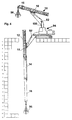
- FIG. 9 shows an implement with the telescopic support on a support module 20 extendable machine part 10.
- the machine part 10 carries over on the inner Section 16 attached adapter 110 a boom arm 112.
- the boom arm 112 is pivotally mounted on the adapter piece 110 in a pivot bearing 114.
- a hydraulic cylinder 116 is also articulated to the adapter piece 110.
- the demolition tool 102 is in turn on the boom arm 112 a pivot bearing 118 hinged.
- On a pivot bearing 120 of the A boom arm 112 is articulated to a hydraulic cylinder 122. Hydraulic cylinder 122 attacks demolition tool 102. As a result, the demolition tool 102 is opposite the boom arm 112 pivotable.
- the boom arm 112 and the demolition tool 102 can in this case be retracted Machine part 10 can be pivoted almost completely around the pivot bearing 114, so that the boom arm 122 and the demolition tool substantially over the Machine part 10 are "folded". Then it is by gravity on machine part 10, boom arm 112 and demolition tool 102 torque exerted if possible low. Overcoming this torque, the telescopically extendable Machine part 10 are pivoted upwards from the actuating cylinder 100, as in FIG. 9 is shown.
- the machine part 10 can then be extended telescopically from this position. This is also shown in Fig.9. So that the boom arm 112 with the Demolition tool 102 moved straight up. The demolition tool 102 can then operate at high altitude. The demolition tool 102 can be reaching around obstacles. To a limited extent, the demolition tool 102, such as is indicated in Fig.9, also work at different heights without this Machine part 10 needs to be retracted.
- the telescopically extendable machine part 10 can for structural reasons often only a smaller number of pressure medium hoses than functions to be controlled are available. For example, there are only two Pressure medium hoses for flow and return are available. However, there are four to control various functions, namely the pivoting of the boom arm 112 by means of the actuating cylinder 116, the pivoting of the demolition tool 102 by means of of the actuating cylinder 122, a rotation of the demolition tool 102 relative to the Boom arm 112 about an axis 126 and the opening and closing of the Demolition tool, e.g. a demolition shear 102. To control these four functions two remote-controllable valve units 128 and 130 are provided.
- Valve units 128 and 130 are located on the boom arm 112. This is shown in FIG. 10 shown.
- the valve unit 128 is connected via two pressure medium hoses 132 and 134 the flow or return connected.
- the valve unit 130 is over two Pressure fluid hoses 136 and 138 are also connected to the flow and return lines. The connection is established via the adapter piece 110.
- the valve unit 128 controls the two pressure medium hoses 140 and 142 Actuating cylinder 116, which pivots the boom arm 112.
- the valve unit 128 controls continue via two pressure medium hoses 144 and 146 the actuating cylinder 122, which the Demolition tool 102 pivoted.
- the demolition tool 102 is controlled via the valve unit 130.
- the valve unit 130 is via two pressure medium hoses 148 and 150 with an actuating unit 152 connected, which rotates the demolition tool 102 about the axis 126.
- the Valve unit 130 is also connected to a pressure medium hose 154 and 156 Actuator 158 connected by which the opening and closing of the Demolition tool 102 e.g. the demolition shear.
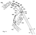
- Fig. 11 The embodiment of Fig. 11 is similar to the embodiment of Figs. 9 and 10. Corresponding parts have the same reference numerals as there.
- a boom arm 112 in a pivot bearing 170 pivoted On the adapter piece 110 at the end of the inner section 16 of the telescopic extendable machine part 10 is a boom arm 112 in a pivot bearing 170 pivoted.
- the formation of the adapter piece 110 and the boom arm 112 and the arrangement of the pivot bearing 170 is such that the boom arm 112 by one large angle of about 180 ° to the telescopically extendable machine part 10 is pivotable.
- a swing arm 172 is also in the adapter piece 110 a pivot bearing 174 is pivotally mounted.
- the rocker arm 172 is via a coupling 176 connected to the boom arm 112.
- a hydraulic actuator in the form of a hydraulic actuating cylinder 178 acts between a pivot bearing 180 on the Boom arm 112 and rocker arm 172.
- Fig.11 the boom arm 112 is in two Positions shown.
- the actuating cylinder 178 is only in the for the sake of clarity pivoted position of the boom arm 112 drawn.
- the kinematic transmission with the rocker arm 172 can optionally be omitted. Then the actuating cylinder attacks directly on the boom arm.
- boom arm 112 in turn is telescopically extendable.
- the demolition tool 102 which is pliers-like here, faces each other the boom arm 112 movable.
- the demolition tool 102 is in a pivot bearing 180 articulated to the free end of the boom arm 112.
- a rocker 184 is pivotally mounted in a pivot bearing 182.
- the swingarm 184 is connected to the demolition tool 102 via a coupling 186.
- a hydraulic actuating cylinder 188 At the Swing arm 184 attacks a hydraulic actuating cylinder 188.
- the actuating cylinder 188 is on the boom arm 112 articulated in a pivot bearing 190. It can also be seen here that by adjusting the demolition tool 102 on the swing arm 184 and Coupling 186 existing kinematic gears a much larger swivel angle is achievable than in the arrangement according to FIG. 10, in which the hydraulic Actuating cylinder 122 directly between boom arm 112 and demolition tool 102 is effective.
- FIG. 12 shows an embodiment with a mobile working device 194, the one has two-part arm 196, wherein a support module 198 for a telescopic extendable machine part 10 instead of the upper section 200, indicated by dashed lines of arm 196 is releasably attached to lower portion 202 of arm 196.
Landscapes
- Engineering & Computer Science (AREA)
- Mechanical Engineering (AREA)
- Structural Engineering (AREA)
- Mining & Mineral Resources (AREA)
- Civil Engineering (AREA)
- General Engineering & Computer Science (AREA)
- Forklifts And Lifting Vehicles (AREA)
- Jib Cranes (AREA)
Applications Claiming Priority (2)
| Application Number | Priority Date | Filing Date | Title |
|---|---|---|---|
| DE1998124282 DE19824282A1 (de) | 1998-05-29 | 1998-05-29 | Mobiles Arbeitsgerät und Bausatz für einen ausfahrbaren Arbeitsarm für ein mobiles Arbeitsgerät |
| DE19824282 | 1998-05-29 |
Publications (2)
| Publication Number | Publication Date |
|---|---|
| EP0960981A2 true EP0960981A2 (fr) | 1999-12-01 |
| EP0960981A3 EP0960981A3 (fr) | 2000-07-19 |
Family
ID=7869441
Family Applications (1)
| Application Number | Title | Priority Date | Filing Date |
|---|---|---|---|
| EP99106190A Withdrawn EP0960981A3 (fr) | 1998-05-29 | 1999-04-09 | Engin mobile de travail et kit d'assemblage pour un bras de travail pour un engin mobile de travail |
Country Status (2)
| Country | Link |
|---|---|
| EP (1) | EP0960981A3 (fr) |
| DE (1) | DE19824282A1 (fr) |
Cited By (5)
| Publication number | Priority date | Publication date | Assignee | Title |
|---|---|---|---|---|
| DE10210694A1 (de) * | 2002-03-12 | 2003-10-09 | Schaeff Terex Gmbh & Co Kg | Baumaschine, insbesondere Kompakt-Baumaschine |
| FR2845405A1 (fr) * | 2002-10-07 | 2004-04-09 | Bernard Coeuret | Mat combine pour un engin de chantier |
| ITTO20091029A1 (it) * | 2009-12-23 | 2011-06-24 | Simone Costamagna | Braccio da demolizione intercambiabile per escavatore idraulico |
| EP2426265A1 (fr) | 2010-09-02 | 2012-03-07 | Demlone | Bras de démolition du type destiné à être relié par une liaison articulée au porteur d'un engin de démolition et engin de démolition équipé d'un tel bras |
| FR2967426A1 (fr) * | 2010-11-17 | 2012-05-18 | Colas Sa | Fleche a benne d'excavation grande profondeur pour pelle mecanique a commande hydraulique et pelle avec une telle fleche |
Families Citing this family (1)
| Publication number | Priority date | Publication date | Assignee | Title |
|---|---|---|---|---|
| ITTO20040053A1 (it) * | 2004-02-03 | 2004-05-03 | Fiat Kobelco Construction Mach | Metodo per configurare il braccio operativo di una macchina movimento terra, macchina provvista di un braccio operativo configurabile, e gruppo adattatore per configurare un braccio operativo |
Family Cites Families (9)
| Publication number | Priority date | Publication date | Assignee | Title |
|---|---|---|---|---|
| US3346300A (en) * | 1966-08-08 | 1967-10-10 | Louis A Grant | Blast furnace lining removing machine |
| US3586113A (en) * | 1969-03-19 | 1971-06-22 | Grant Inc Louis A | Demolition and scooping machine |
| SE402753B (sv) * | 1977-03-21 | 1978-07-17 | Jonsereds Fabrikers Ab | Anordning av slangforing och hydroulkoppling vid hydrauliskt manovrerad kran |
| US4274796A (en) * | 1979-04-04 | 1981-06-23 | Alexander Shand Services Limited | Machine comprising a rotatable boom assembly |
| NL8003248A (nl) * | 1979-07-03 | 1981-01-06 | Liebherr Hydraulikbagger | Uithouder met beweegbaar daaraan verbonden lepelsteel voor hydraulisch baggerwerktuig of dergelijke. |
| JPS5972327A (ja) * | 1982-10-19 | 1984-04-24 | Hitachi Constr Mach Co Ltd | 伸縮ア−ム付クラムシエルの油圧回路 |
| US5486084A (en) * | 1993-06-07 | 1996-01-23 | Raymond F. Pitman | Multiple purpose material handling and working apparatus |
| DE4498218T1 (de) * | 1993-10-27 | 1996-12-05 | Komatsu Mfg Co Ltd | Arbeitsmaschine eines hydraulischen Tiefbaggers |
| CH693222A5 (de) * | 1997-07-15 | 2003-04-30 | Robert Schnyder | Greifer für einen Bagger, Baggersowie Verwendungen derselben insbesondere imForstbereich. |
-
1998
- 1998-05-29 DE DE1998124282 patent/DE19824282A1/de not_active Withdrawn
-
1999
- 1999-04-09 EP EP99106190A patent/EP0960981A3/fr not_active Withdrawn
Cited By (7)
| Publication number | Priority date | Publication date | Assignee | Title |
|---|---|---|---|---|
| DE10210694A1 (de) * | 2002-03-12 | 2003-10-09 | Schaeff Terex Gmbh & Co Kg | Baumaschine, insbesondere Kompakt-Baumaschine |
| FR2845405A1 (fr) * | 2002-10-07 | 2004-04-09 | Bernard Coeuret | Mat combine pour un engin de chantier |
| EP1408162A1 (fr) * | 2002-10-07 | 2004-04-14 | Bernard Coeuret | Mât combiné pour un engin de chantier |
| ITTO20091029A1 (it) * | 2009-12-23 | 2011-06-24 | Simone Costamagna | Braccio da demolizione intercambiabile per escavatore idraulico |
| EP2426265A1 (fr) | 2010-09-02 | 2012-03-07 | Demlone | Bras de démolition du type destiné à être relié par une liaison articulée au porteur d'un engin de démolition et engin de démolition équipé d'un tel bras |
| FR2964397A1 (fr) * | 2010-09-02 | 2012-03-09 | Demlone | Bras de demolition du type destine a etre relie par une liaison articulee au porteur d'un engin de demolition et engin de demolition equipe d'un tel bras |
| FR2967426A1 (fr) * | 2010-11-17 | 2012-05-18 | Colas Sa | Fleche a benne d'excavation grande profondeur pour pelle mecanique a commande hydraulique et pelle avec une telle fleche |
Also Published As
| Publication number | Publication date |
|---|---|
| EP0960981A3 (fr) | 2000-07-19 |
| DE19824282A1 (de) | 2000-01-13 |
Similar Documents
| Publication | Publication Date | Title |
|---|---|---|
| DE3517853A1 (de) | Ausfahrbare vorrichtung | |
| DE69203917T2 (de) | Werkzeugwechselvorrichtung einer Erdbaumaschine. | |
| EP2781682B1 (fr) | Petite foreuse | |
| DE3142100A1 (de) | "gelenk-ausleger fuer bagger" | |
| EP0960981A2 (fr) | Engin mobile de travail et kit d'assemblage pour un bras de travail pour un engin mobile de travail | |
| DE4233730A1 (de) | Maschine für Erdarbeiten | |
| DE3014664A1 (de) | Hydraulischer schubloeffelbagger | |
| DE60007227T2 (de) | Selbstangetriebener Wagen mit teleskopischem Arm und Hebungsarm | |
| DE1634733C3 (de) | Hochlöffelbagger | |
| DE4120584A1 (de) | Anbaugeraet an einem auslegerarm, insbesondere eines mobilbaggers | |
| DE19806057A1 (de) | Baumaschinenadapter | |
| DE102005027596B4 (de) | Eisenbahnkran | |
| DE2424486A1 (de) | Baumaschine | |
| DE60310207T2 (de) | Arbeitsbühne | |
| DE2501780A1 (de) | Hydraulikbagger | |
| DE102006004207B4 (de) | Gegabelter Ausleger für einen Bagger | |
| DE102008026173A1 (de) | Arbeitsausleger für ein Vielzweckfahrzeug | |
| DE3227136A1 (de) | Lade- und baggergeraet | |
| DE4139379A1 (de) | Arbeitsmaschine fuer abbruch-, lade- und grabearbeiten | |
| EP4056763B1 (fr) | Machine de travail mobile, en particulier pelle excavatrice, comportant un châssis de véhicule et un bras de levage | |
| EP3575497A1 (fr) | Drague aspiratrice | |
| EP0117261A1 (fr) | Bras de travail pour engins de terrassement et de fondations | |
| DE3905596A1 (de) | Fahrbares bohrgeraet | |
| DE2612879A1 (de) | Fahrbarer loeffelbagger | |
| DE102016011579A1 (de) | "Vorrichtung zur Führung wenigstens eines Werkzeuges" - kombiniert mit einer Schürfzugeinheit |
Legal Events
| Date | Code | Title | Description |
|---|---|---|---|
| PUAI | Public reference made under article 153(3) epc to a published international application that has entered the european phase |
Free format text: ORIGINAL CODE: 0009012 |
|
| AK | Designated contracting states |
Kind code of ref document: A2 Designated state(s): AT BE CH CY DE DK ES FI FR GB GR IE IT LI LU MC NL PT SE |
|
| AX | Request for extension of the european patent |
Free format text: AL;LT;LV;MK;RO;SI |
|
| PUAL | Search report despatched |
Free format text: ORIGINAL CODE: 0009013 |
|
| AK | Designated contracting states |
Kind code of ref document: A3 Designated state(s): AT BE CH CY DE DK ES FI FR GB GR IE IT LI LU MC NL PT SE |
|
| AX | Request for extension of the european patent |
Free format text: AL;LT;LV;MK;RO;SI |
|
| RIC1 | Information provided on ipc code assigned before grant |
Free format text: 7E 02F 3/38 A, 7E 02F 3/96 B, 7E 02F 3/30 B |
|
| AKX | Designation fees paid | ||
| STAA | Information on the status of an ep patent application or granted ep patent |
Free format text: STATUS: THE APPLICATION IS DEEMED TO BE WITHDRAWN |
|
| 18D | Application deemed to be withdrawn |
Effective date: 20010120 |
|
| REG | Reference to a national code |
Ref country code: DE Ref legal event code: 8566 |