EP0961128A2 - Modulare Einrichtung zur mechanischen Befestigung und automatischen Handhabung von Leiterplattenbaugruppen für eine automatische Testeinrichtung - Google Patents
Modulare Einrichtung zur mechanischen Befestigung und automatischen Handhabung von Leiterplattenbaugruppen für eine automatische Testeinrichtung Download PDFInfo
- Publication number
- EP0961128A2 EP0961128A2 EP98123648A EP98123648A EP0961128A2 EP 0961128 A2 EP0961128 A2 EP 0961128A2 EP 98123648 A EP98123648 A EP 98123648A EP 98123648 A EP98123648 A EP 98123648A EP 0961128 A2 EP0961128 A2 EP 0961128A2
- Authority
- EP
- European Patent Office
- Prior art keywords
- assembly
- testing
- modular
- press
- primary frame
- Prior art date
- Legal status (The legal status is an assumption and is not a legal conclusion. Google has not performed a legal analysis and makes no representation as to the accuracy of the status listed.)
- Granted
Links
Images



Classifications
-
- G—PHYSICS
- G01—MEASURING; TESTING
- G01R—MEASURING ELECTRIC VARIABLES; MEASURING MAGNETIC VARIABLES
- G01R31/00—Arrangements for testing electric properties; Arrangements for locating electric faults; Arrangements for electrical testing characterised by what is being tested not provided for elsewhere
- G01R31/28—Testing of electronic circuits, e.g. by signal tracer
- G01R31/2801—Testing of printed circuits, backplanes, motherboards, hybrid circuits or carriers for multichip packages [MCP]
- G01R31/2806—Apparatus therefor, e.g. test stations, drivers, analysers, conveyors
- G01R31/2808—Holding, conveying or contacting devices, e.g. test adapters, edge connectors, extender boards
Definitions
- the present invention relates generally to testing of printed circuit boards for use in electronic products and, specifically, to a press for engaging a printed circuit board to a probe card assembly.
- testers utilize a "bed-of-nails" design, which includes a probe surface having plural (thousands) of sockets that are interconnected to test equipment, such as a computer wit the appropriate software.
- Test probes are insertable in these sockets and protrude upwardly from the probe surface. These probes are configured to match the input/output connection points of the electronic components, such as integrated circuits, resident on the printed circuit board (PCB) being tested. Further, the probes are biased upwardly such that, to ensure proper alignment, a card must be placed over the probes and sufficient downward force must be provided to the PCB such that proper electrical connection is made between the inputs/outputs of the electronic components and the test equipment, via the biased test probes.
- PCB printed circuit board
- Fixturing systems have been developed for purposes of handling printed circuit boards for testing.
- the most common of such fixturing systems is a vacuum fixture.
- vacuum fixturing atmospheric pressure acts directly on a PCB with a vacuum beneath it, forcing the board against spring loaded testing probes. Problems rise from the need to maintain a seal around and across the board. Maintaining a vacuum seal in an automated environment is even more troublesome.
- Warped printed circuit boards are commonly encountered and require a separate effort or effect to push and seat them in the fixture gasketing material. PCBs with holes or apertures generally complicate vacuum fixturing techniques because of the difficulty associated with maintaining a proper seal.
- probe density is limited by atmospheric pressure.
- vacuum fixtures generally do not provide sufficiently forceful contact between the probes and PCBs to displace contaminants present on the board surfaces, thereby necessitating additional costs and chemical disposal issues associated with pre-cleaning the boards before testing.
- the typical pneumatic fixturing system incorporates a flat plate attached to a cylinder. Pneumatic pressure is applied to the cylinder which in turn forces the plate against the printed circuit board disposed on the probes. Testing problems arise from the fact that the center of the plate receives the majority of the force applied by the cylinder. Accordingly, the periphery of the board may not sufficiently contact and be tested by the probes. This is especially true with large and/or thin PCBs. Further, such pneumatic systems are not height adjustable relative the probes and thus are unable to accommodate boards of varying thicknesses and/or component heights.
- a printed circuit board testing system that enables rapid and evenly distributed pressing of the boards to the test probes, allows adjustability of the press height so as to accommodate differently sized boards, and is modifiable to multiple configurations so as to enable multiple modes of operation.
- a modular multi-configuration upgradeable testing system for quickly and accurately testing printed circuit boards in conjunction with a conventional probe card testing assembly is disclosed.
- a testing system incorporating a modular primary frame having multiple mounting surfaces and mounted on a conventional probe card testing assembly.
- At least one modular press assembly is attached to the primary frame.
- the press assembly is height adjustable relative the testing assembly and has a plurality of synchronized force-applying members.
- a modular conveyor assembly comprising at least one conveyor rail pair may be attached to at least one primary frame mounting surface.
- the rail pair is configured to deliver a printed circuit board (PCB) to the testing assembly and to withdraw a printed circuit board from the testing assembly.
- a modular interface assembly comprising a bar code reader, a PCB marker or other similar devices may be disposed within the primary frame and is height adjustable relative the testing assembly.
- a modular secondary frame attached to at least one primary frame mounting surface may house the interface.
- a controller controls and coordinates the testing functions of the testing assembly in addition to controlling and coordinating the delivery and withdrawal functions of the conveyor rail pair and the functions associated with the modular interface assembly.
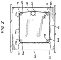
- a PCB press 10 includes a stationary frame 20 having flanges 50, which are attached to a conventional probe card testing assembly 30.
- Probe card testing assembly 30 includes a conventional probe card 40 used for testing a printed circuit board 160.
- PCB press 10 comprises press assembly 100, which is a fast-acting press tat moves press plate 150 rapidly through a fixed stroke.
- Press assembly 100 is height adjustable within frame 20 by means of lead screw assemblies 70A, 70B, 70C, and 70D disposed substantially proximal the peripheral corners of press assembly 100.
- lead screw assemblies 70A are described in detail, however, lead screw assemblies 70B-70D comprise substantially identical elements.
- Lead screw assembly 70A comprises an upper bearing portion 86A that rotates within but is constrained in the axial direction by bearing journal 88A disposed in press mount 60 of frame 20.
- Lower portion 90A of lead screw assembly 70A is threaded into a threaded boss 92A in press assembly upper plate 110 such that, when lead screw 70A is rotated, upper plate 110 (and with it press assembly 100) are drawn toward or forced away from press mount 60 of frame 20.
- a driving member 80A Disposed atop lead screw assembly 70 is a driving member 80A, which preferably comprises a gear, chain sprocket, timing belt pulley or similar apparatus for receiving synchronized power transmission.
- lead screw assemblies 70A-70D are disposed proximal the peripheral corners 72,73,74 75 of press assembly upper plate 110 (shown in dashed lines in FIG. 2).
- a conventional link-and-roller chain 170 engages driving members 80A-80D in conventional fashion to cause the rotation of all of lead screw assemblies 70A-70D to be synchronized.
- upper plate 110 can be moved toward or away from press mount 60 of frame 20 while maintaining upper plate 110 in a precisely horizontal attitude.
- stabilizer rail 210 is rigidly mounted in press mount 60 so as to slidingly engage a stabilizer bushing 212 in press assembly upper plate 110. Additional stabilizer rails may be added as required for the particular application.
- Lead screw assemblies 70A-70D may be manually adjusted or, as shown in FIG. 2, a drive motor 190 may be coupled via sprocket 210 to chain 170 thereby providing a power-adjustment feature.
- a conventional link-and-roller chain is disclosed in the illustrative embodiment, a timing belt, gear train, flexible shafting, or any other conventional means of synchronously driving a plurality of parallel shafts is contemplated within the present invention.
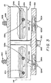
- FIG. 3 is a partial cross-section of FIG. 1 along line 3-3 with the press plate 150 near the fully extended position (press plate 150 is shown fully refracted in FIG. 1).
- press assembly 100 comprises side plates 101A and 101B, which are rigidly attached to opposite sides of press assembly upper plate 110.
- Each of side plates 101A and 101B support substantially equivalent actuator mechanisms 120A (FIG. 3) and 120B (not shown). Accordingly, for the sake of brevity, only the actuator mechanism supported by side plate 101A is discussed in detail herein.
- Side plate 101A has a channel 102A formed therein. Disposed within channel 102A is a linear gear, also known as a rack, 104A.
- Rack 104A engages driven pinions 106A and 108A and also engages a drive pinion 112A.
- Driven pinions 106A and 108A are coupled to bell crank arms 116A and 118A, respectively.
- Crank pins 122A and 124A, respectively, are disposed transversely in bell crank arms 116A and 118A, respectively, such that the distance from the center of pinion 106A to crank pin 122A is equal to the distance from the center of pinion 108A to crank pin 124A.
- Crank pin 122A engages a corresponding slot 132A in press plate 150 and crank pin 124A engages a corresponding slot 134A in press plate 150.
- rotary actuator 114 rotates drive pinion 112A, which in turn causes rack 104A to translate along channel 102A.
- Translation of rack 104A causes pinions 106A and 108A to rotate in unison, which causes bell crank arms 116A and 118A also to rotate in unison, thereby extending press plate 150 downward.
- Guide rail 300 is rigidly mounted to press assembly upper plate 110 such that it engages a guide bushing 310 in press plate 150.
- Guide rail 300 thereby constrains press plate 150 to move vertically along guide 300 as bell crank arms 116A and 118A rotate. Because bell crank arms 116A and 118A move in unison, press plate 150 is extended downward with equal downward pressure at both ends.
- the vertical force exerted by bell crank arms 116A and 118A is a function of 1/sin of the angle between bell crank arms 116A and 118A and the horizontal. Since 1/sin approaches infinity as the angle approaches 90 degrees, the vertical force multiplication exerted by bell crank arms 116A and 118A is highest at the beginning and end of the stroke. Thus, the actuator mechanism 120A moves rapidly through most of the stroke yet is able to exert a substantial downward force on the PCB being tested at the end of the stroke, with a modest torque exerted at pinions 106A and 108A. In the illustrative embodiment, the distance between the center of pinions 106A and 108A is two inches. Thus, the total stroke of press plate 150 with bell crank arms 116A and 118A moving through 180 degrees is four inches.
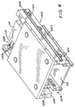
- FIG. 4 is an isometric perspective view of press assembly 100.
- side plate 101B supports an actuator mechanism 120B, which is a functionally identical, mirror image of actuator mechanism 120A discussed herein.
- rotary actuator 114 comprises a conventional double-ended actuator having a common shaft 115 that drives both driven pinion 112A of actuator mechanism 120A and a corresponding driven pinion 112B of actuator mechanism 120B.
- rack 104A and rack 104B are translated synchronously within corresponding channels 102A and 102B. This in turn ensures tat actuator mechanism 120A and 120B are synchronized and, therefore, that equal pressure is applied to all four corners of press plate 150.
- Rotary actuator may 114 may be electrically or vacuum operated, but is preferably a conventional pneumatic rotary actuator.
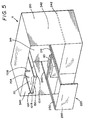
- dual bay PCB press 11 is shown with press assembly 100 disposed within stationary frame 210, which comprises a dual-bay version of frame 20 including removable panels 340, 341 and 342. Any of panels 340, 341, 342 and 343 may be removed to facilitate automated conveyor rail operation as is more fully described hereinafter.
- an optional shuttle system 220 enabling mechanical placement of circuit board 160 upon testing assembly 30.
- Shuffle system 220 consists of at least one drawer 230 and a drawer support that may take the form of a set of rails 240, 241 and 242. Rails 240, 241 and 242 allow drawer 230 to move in and out of frame 20 and to be placed in a position below press assembly 100 for circuit board 160 testing.
- Movement of drawer 230 in an out of frame 20 may be manually or automatically produced.
- Drawer 230 has a substantially open bottom surface 250 that simultaneously supports a circuit board 160 placed thereon and enables interfacing forced by press plate 150 between circuit board 160 and probe card 40.
- Shuttle system 220 protects the fragile probe card assembly by providing a bed into which the operator places the PCB remote from the probe card assembly and thus enables precise regulation of the extent to which the PCB contacts the probe card assembly.
- Conveyor rail 350A which, when combined with similarly constructed elements, may be employed to convey PCBs to PCB press 10 or PCB press 11 to facilitate automated PCB testing.
- Conveyor rail 350A includes drive wheels 360 and 361, each of which is bi-directionally rotatably mounted on rail frame 370 at opposite ends of conveyor rail 350A.
- a continuous conveyor belt 380 having a substantially flat outer surface 381 is stretched between and engaged by drive wheels 360 and 361 such that rotation of wheels 360 and 361 causes corresponding rotation of conveyor belt 380.
- Belt 380 is caused to move by incorporating a motor to drive at least one of wheels 360 and 361 or by use of a driven snubbing roller 383 that engages the underside 385 of belt 380.
- belt 380 may be self-propelled by incorporating a drive motor into frame 370 itself.
- successive conveyor rails may be placed in series in order to transport the PCBs a relatively large distance.
- FIG. 7 is a cross-section of FIG. 6 taken along line 7-7 and shows an illustrative means of attaching modular conveyor rail 350A to any one of panels 340, 341, 342 or 343.
- Rail frame 370 incorporates a dovetail fixture 400 that is slidably and securely engaged by dovetail groove 390.
- Dovetail groove 390 is attached to panel 340 by screws, welds or any of a number of other fastening means known in the art.
- Belt 380 extends beyond innermost edge 371 of rail frame 370 by a clearance distance X to form a lip 382 on which a PCB may ride as disclosed hereinafter.
- X is equal to three millimeters but may vary depending on PCB specifications and system tolerances.
- FIG. 8 shows a PCB 160 being transported by cooperating conveyor rails 350A and 350B.
- the outer surfaces 381 and 383 of conveyor belts 380 and 385 support and contact only opposing edges of PCB 160 thereby leaving circuitry disposed along the bottom of PCB 160 exposed for testing.
- FIG. 9 is a perspective view of dual bay PCB press 11 wherein removable panels 341 and 343 have been removed from stationary frame 210 while removable panels 340 and 342 have been attached thereto.
- dual bay automated PCB testing may be conducted through the installation and use of functionally identical modular conveyor rail pair 350 comprising conveyor rails 350A and 350B and conveyor rail pair 351 comprising conveyor rails 351A and 351B.
- Conveyor rail 350A is attached to panel 340 and conveyor rail 351A is attached to panel 342 in the manner illustrated in FIG. 7.
- Conveyor rails 350B and 351B are attached to and supported by a conventional support means (not shown) disposed within press 11 such that rail pairs 350 and 351 are cooperatively configured as illustrated in FIG. 8.
- Conveyor rail pair 350 transports PCB 160 through press entry 420 and to a testing position above probe card 40 and below press assembly 100 where PCB 160 is tested. While PCB 160 is being tested, rail pair 351 may stage PCB 161 by transporting PCB 161 through press entry 420 and to a testing position above probe card 41 and below a second press assembly (not shown). Once PCB 160 has been tested, PCB 161 is then tested while rail pair 350 simultaneously transports PCB 160 out of press 11 through press exit 430 and stages a successive PCB above probe card 40 and below press assembly 100. Alternatively, rail pairs 350 and 351 may transport PCBs through press entry 420 into press 11 where the PCBs are staged and pressed and subsequently transport the tested PCBs out of press 11 through press entry 420.
- FIG. 10 shows the invention as illustrated in FIG. 9 further incorporating a modular secondary frame 440 disposed above rail pair 350 and attached by conventional means to frame 210 exterior of press 11.
- a modular interface assembly 410 is attached to and height adjustable within frame 440 by means of structure functionally identical and structurally similar to that associated with press assembly 100 and press mount 60. Accordingly, once PCB 160 has been tested and transported through press exit 430, other functions may be performed on PCB 160 by bar code scanners, board markers or other devices incorporated by interface assembly 410.
- secondary frame 440 and interface assembly 410 may also be disposed within an enlarged press frame, essentially the same width and twice as deep as press 11, without loss of optimal functional capabilities.
- FIG. 11 is a cutaway perspective view of PCB press 11 wherein removable panels 341 and 343 have been attached to stationary frame 210 while removable panels 340 and 342 have been removed therefrom.
- automated PCB testing of lower capacity and complexity than that illustrated in FIGs 9 and 10 may be conducted through the installation and use of modular conveyor rail pair 350 comprised of conveyor rail 350A attached to panel 341 and conveyor rail 350B attached to panel 343.
- Conveyor rail 350 transports PCB 160 trough press entry 450 to a testing position above probe card 40 and below press assembly 100 where PCB 160 is tested. After PCB 160 is tested, rail pair 350 transports PCB 160 out of press 11 through press exit 460.
- Modular secondary frame 440 and modular interface assembly 410 are disposed within press 11 and above a portion of rail pair 350 to enable scanning, marking or other operations to be performed on PCB 160 while present within press 11.
- secondary frame 440 and interface assembly 410 may also be disposed exterior of press 11 without loss of optimal functional capabilities.
- microcontroller 800 may be employed to coordinate the discrete functions of each invention component.
Landscapes
- Engineering & Computer Science (AREA)
- Computer Hardware Design (AREA)
- Microelectronics & Electronic Packaging (AREA)
- General Engineering & Computer Science (AREA)
- Physics & Mathematics (AREA)
- General Physics & Mathematics (AREA)
- Tests Of Electronic Circuits (AREA)
Priority Applications (1)
| Application Number | Priority Date | Filing Date | Title |
|---|---|---|---|
| EP03024875A EP1394556A3 (de) | 1998-05-29 | 1998-12-10 | Modulare Einrichtung zur mechanischen Befestigung und automatischen Handhabung von Leiterplattenbaugruppen für eine automatische Testeinrichtung |
Applications Claiming Priority (2)
| Application Number | Priority Date | Filing Date | Title |
|---|---|---|---|
| US09/087,006 US6307386B1 (en) | 1998-05-29 | 1998-05-29 | Modular mechanical fixturing and automated handling of printed circuit assemblies on automated test equipment |
| US87006 | 1998-05-29 |
Related Child Applications (1)
| Application Number | Title | Priority Date | Filing Date |
|---|---|---|---|
| EP03024875A Division EP1394556A3 (de) | 1998-05-29 | 1998-12-10 | Modulare Einrichtung zur mechanischen Befestigung und automatischen Handhabung von Leiterplattenbaugruppen für eine automatische Testeinrichtung |
Publications (3)
| Publication Number | Publication Date |
|---|---|
| EP0961128A2 true EP0961128A2 (de) | 1999-12-01 |
| EP0961128A3 EP0961128A3 (de) | 2001-03-21 |
| EP0961128B1 EP0961128B1 (de) | 2004-08-18 |
Family
ID=22202330
Family Applications (2)
| Application Number | Title | Priority Date | Filing Date |
|---|---|---|---|
| EP98123648A Expired - Lifetime EP0961128B1 (de) | 1998-05-29 | 1998-12-10 | Modulare Einrichtung zur mechanischen Befestigung und automatischen Handhabung von Leiterplattenbaugruppen für eine automatische Testeinrichtung |
| EP03024875A Withdrawn EP1394556A3 (de) | 1998-05-29 | 1998-12-10 | Modulare Einrichtung zur mechanischen Befestigung und automatischen Handhabung von Leiterplattenbaugruppen für eine automatische Testeinrichtung |
Family Applications After (1)
| Application Number | Title | Priority Date | Filing Date |
|---|---|---|---|
| EP03024875A Withdrawn EP1394556A3 (de) | 1998-05-29 | 1998-12-10 | Modulare Einrichtung zur mechanischen Befestigung und automatischen Handhabung von Leiterplattenbaugruppen für eine automatische Testeinrichtung |
Country Status (3)
| Country | Link |
|---|---|
| US (1) | US6307386B1 (de) |
| EP (2) | EP0961128B1 (de) |
| DE (1) | DE69825727T2 (de) |
Cited By (4)
| Publication number | Priority date | Publication date | Assignee | Title |
|---|---|---|---|---|
| EP1530055A1 (de) * | 2003-11-10 | 2005-05-11 | Teco GmbH | Vorrichtung zum Prüfen elektrischer Bauteile |
| CN106646194A (zh) * | 2016-12-22 | 2017-05-10 | 重庆淳祥电子科技有限公司 | 键盘电路测试设备 |
| CN108896858A (zh) * | 2018-07-16 | 2018-11-27 | 博众精工科技股份有限公司 | 随动电芯短路测试机构及电芯短路测试系统 |
| CN118566788A (zh) * | 2024-08-05 | 2024-08-30 | 国网山东省电力公司临清市供电公司 | 电力系统继电保护二次回路拆接对接校验器 |
Families Citing this family (45)
| Publication number | Priority date | Publication date | Assignee | Title |
|---|---|---|---|---|
| DE10014199C1 (de) * | 2000-03-22 | 2001-12-13 | Siemens Ag | Vorrichtung zum Transport von Leiterplatten |
| US6667631B2 (en) | 2001-12-27 | 2003-12-23 | Stmicroelectronics, Inc. | High temperature probe card |
| US6719199B1 (en) | 2003-04-29 | 2004-04-13 | International Business Machines Corporation | Credit card/smart card test device |
| US7161347B1 (en) * | 2005-07-08 | 2007-01-09 | Credence Systems Corporation | Test head for semiconductor integrated circuit tester |
| DE202006010086U1 (de) * | 2006-06-27 | 2006-08-31 | Suss Microtec Test Systems Gmbh | Adapter zur Positionierung von Kontaktspitzen |
| US7400135B1 (en) * | 2007-02-23 | 2008-07-15 | Quality One Test Fixturing, Inc. | Test fixture and method for circuit board testing |
| US7996174B2 (en) | 2007-12-18 | 2011-08-09 | Teradyne, Inc. | Disk drive testing |
| US8549912B2 (en) | 2007-12-18 | 2013-10-08 | Teradyne, Inc. | Disk drive transport, clamping and testing |
| US8238099B2 (en) | 2008-04-17 | 2012-08-07 | Teradyne, Inc. | Enclosed operating area for disk drive testing systems |
| US7945424B2 (en) | 2008-04-17 | 2011-05-17 | Teradyne, Inc. | Disk drive emulator and method of use thereof |
| US7848106B2 (en) | 2008-04-17 | 2010-12-07 | Teradyne, Inc. | Temperature control within disk drive testing systems |
| US8041449B2 (en) | 2008-04-17 | 2011-10-18 | Teradyne, Inc. | Bulk feeding disk drives to disk drive testing systems |
| US8305751B2 (en) | 2008-04-17 | 2012-11-06 | Teradyne, Inc. | Vibration isolation within disk drive testing systems |
| US8160739B2 (en) | 2008-04-17 | 2012-04-17 | Teradyne, Inc. | Transferring storage devices within storage device testing systems |
| US8102173B2 (en) | 2008-04-17 | 2012-01-24 | Teradyne, Inc. | Thermal control system for test slot of test rack for disk drive testing system with thermoelectric device and a cooling conduit |
| US8095234B2 (en) | 2008-04-17 | 2012-01-10 | Teradyne, Inc. | Transferring disk drives within disk drive testing systems |
| US20090262455A1 (en) | 2008-04-17 | 2009-10-22 | Teradyne, Inc. | Temperature Control Within Disk Drive Testing Systems |
| US8117480B2 (en) | 2008-04-17 | 2012-02-14 | Teradyne, Inc. | Dependent temperature control within disk drive testing systems |
| WO2009148942A2 (en) | 2008-06-03 | 2009-12-10 | Teradyne, Inc. | Processing storage devices |
| US7995349B2 (en) | 2009-07-15 | 2011-08-09 | Teradyne, Inc. | Storage device temperature sensing |
| US8466699B2 (en) | 2009-07-15 | 2013-06-18 | Teradyne, Inc. | Heating storage devices in a testing system |
| US8116079B2 (en) | 2009-07-15 | 2012-02-14 | Teradyne, Inc. | Storage device testing system cooling |
| US8687356B2 (en) | 2010-02-02 | 2014-04-01 | Teradyne, Inc. | Storage device testing system cooling |
| US7920380B2 (en) | 2009-07-15 | 2011-04-05 | Teradyne, Inc. | Test slot cooling system for a storage device testing system |
| US8547123B2 (en) | 2009-07-15 | 2013-10-01 | Teradyne, Inc. | Storage device testing system with a conductive heating assembly |
| US8628239B2 (en) | 2009-07-15 | 2014-01-14 | Teradyne, Inc. | Storage device temperature sensing |
| US9779780B2 (en) | 2010-06-17 | 2017-10-03 | Teradyne, Inc. | Damping vibrations within storage device testing systems |
| US8687349B2 (en) | 2010-07-21 | 2014-04-01 | Teradyne, Inc. | Bulk transfer of storage devices using manual loading |
| KR20120112648A (ko) * | 2010-08-17 | 2012-10-11 | 가부시키가이샤 아드반테스트 | 접속 장치, 그것을 구비한 반도체 웨이퍼 시험 장치 및 접속 방법 |
| US9001456B2 (en) | 2010-08-31 | 2015-04-07 | Teradyne, Inc. | Engaging test slots |
| US9459312B2 (en) | 2013-04-10 | 2016-10-04 | Teradyne, Inc. | Electronic assembly test system |
| US9726718B2 (en) * | 2014-05-30 | 2017-08-08 | Skyworks Solutions, Inc. | Modular test fixture |
| US10845410B2 (en) | 2017-08-28 | 2020-11-24 | Teradyne, Inc. | Automated test system having orthogonal robots |
| US10948534B2 (en) | 2017-08-28 | 2021-03-16 | Teradyne, Inc. | Automated test system employing robotics |
| US10725091B2 (en) | 2017-08-28 | 2020-07-28 | Teradyne, Inc. | Automated test system having multiple stages |
| US11226390B2 (en) | 2017-08-28 | 2022-01-18 | Teradyne, Inc. | Calibration process for an automated test system |
| CN107942232B (zh) * | 2017-11-28 | 2024-08-09 | 北京日扬弘创科技有限公司 | 自动测试设备 |
| US10983145B2 (en) | 2018-04-24 | 2021-04-20 | Teradyne, Inc. | System for testing devices inside of carriers |
| US10775408B2 (en) | 2018-08-20 | 2020-09-15 | Teradyne, Inc. | System for testing devices inside of carriers |
| US11754622B2 (en) | 2020-10-22 | 2023-09-12 | Teradyne, Inc. | Thermal control system for an automated test system |
| US11899042B2 (en) | 2020-10-22 | 2024-02-13 | Teradyne, Inc. | Automated test system |
| US11754596B2 (en) | 2020-10-22 | 2023-09-12 | Teradyne, Inc. | Test site configuration in an automated test system |
| US11867749B2 (en) | 2020-10-22 | 2024-01-09 | Teradyne, Inc. | Vision system for an automated test system |
| US11953519B2 (en) | 2020-10-22 | 2024-04-09 | Teradyne, Inc. | Modular automated test system |
| US12007411B2 (en) | 2021-06-22 | 2024-06-11 | Teradyne, Inc. | Test socket having an automated lid |
Family Cites Families (8)
| Publication number | Priority date | Publication date | Assignee | Title |
|---|---|---|---|---|
| US4357575A (en) * | 1980-06-17 | 1982-11-02 | Dit-Mco International Corporation | Apparatus for use in testing printed circuit process boards having means for positioning such boards in proper juxtaposition with electrical contacting assemblies |
| US4471298A (en) * | 1981-12-11 | 1984-09-11 | Cirdyne, Inc. | Apparatus for automatically electrically testing printed circuit boards |
| US4845843A (en) * | 1985-10-28 | 1989-07-11 | Cimm, Inc. | System for configuring, automating and controlling the test and repair of printed circuit boards |
| US4818933A (en) * | 1986-10-08 | 1989-04-04 | Hewlett-Packard Company | Board fixturing system |
| DE3713155A1 (de) * | 1987-04-15 | 1988-11-03 | Schmidt & Link Werkzeugbau Gmb | Einrichtung zum automatischen programmierten pruefen von prueflingen aller art |
| JPH01185455A (ja) | 1988-01-20 | 1989-07-25 | Nec Home Electron Ltd | 機能検査システム |
| US5094584A (en) * | 1989-04-06 | 1992-03-10 | Hewlett-Packard Company | Method and apparatus for automatically changing printed circuit board test fixtures |
| IT1266653B1 (it) * | 1993-11-02 | 1997-01-09 | Circuit Line Spa | Macchina per eseguire il test elettrico simultaneo, sulle due facce di una piastra con circuiti stampati |
-
1998
- 1998-05-29 US US09/087,006 patent/US6307386B1/en not_active Expired - Fee Related
- 1998-12-10 DE DE69825727T patent/DE69825727T2/de not_active Expired - Fee Related
- 1998-12-10 EP EP98123648A patent/EP0961128B1/de not_active Expired - Lifetime
- 1998-12-10 EP EP03024875A patent/EP1394556A3/de not_active Withdrawn
Cited By (4)
| Publication number | Priority date | Publication date | Assignee | Title |
|---|---|---|---|---|
| EP1530055A1 (de) * | 2003-11-10 | 2005-05-11 | Teco GmbH | Vorrichtung zum Prüfen elektrischer Bauteile |
| CN106646194A (zh) * | 2016-12-22 | 2017-05-10 | 重庆淳祥电子科技有限公司 | 键盘电路测试设备 |
| CN108896858A (zh) * | 2018-07-16 | 2018-11-27 | 博众精工科技股份有限公司 | 随动电芯短路测试机构及电芯短路测试系统 |
| CN118566788A (zh) * | 2024-08-05 | 2024-08-30 | 国网山东省电力公司临清市供电公司 | 电力系统继电保护二次回路拆接对接校验器 |
Also Published As
| Publication number | Publication date |
|---|---|
| EP0961128A3 (de) | 2001-03-21 |
| DE69825727D1 (de) | 2004-09-23 |
| EP1394556A2 (de) | 2004-03-03 |
| EP0961128B1 (de) | 2004-08-18 |
| US6307386B1 (en) | 2001-10-23 |
| EP1394556A3 (de) | 2004-05-26 |
| DE69825727T2 (de) | 2005-09-01 |
Similar Documents
| Publication | Publication Date | Title |
|---|---|---|
| EP0961128B1 (de) | Modulare Einrichtung zur mechanischen Befestigung und automatischen Handhabung von Leiterplattenbaugruppen für eine automatische Testeinrichtung | |
| US4818933A (en) | Board fixturing system | |
| EP0387332A1 (de) | Testanordnung für halbleiterschaltungen | |
| US5055779A (en) | Integrated board testing system | |
| EP0961127B1 (de) | Verstellbare, schnelle Druckeinrichtung mit einem Schlitten für eine Leiterplatte und modular erweiterbaren Fähigkeiten | |
| CN210182278U (zh) | 一种全自动键盘剪刀脚组装机 | |
| JP2011017692A (ja) | 基板収納容器、及びこれを具備した基板検査装置 | |
| CN106824829A (zh) | Ict转盘测试机 | |
| JP2000258507A (ja) | モジュールicハンドラーのキャリアハンドリング装置及びその方法 | |
| US6867579B2 (en) | Testing system in a circuit board manufacturing line for automatic testing of circuit boards | |
| CN115372789A (zh) | 一种电子元件加工用线路板测试装置 | |
| CN105775640A (zh) | 一种双轨接驳台及其运行方法、以及采用双轨接驳台的自动化生产线 | |
| US4993136A (en) | Method of converting a vacuum test fixture on a board testing apparatus to a mechanical test fixture | |
| KR102557253B1 (ko) | Pcb cnt와 ffc의 자동 체결 및 해체 시스템 | |
| GB2136140A (en) | Automatic Testing Machine for Printed Circuits | |
| US6232766B1 (en) | Test station for sequential testing | |
| IE20010536A1 (en) | A test fixture for testing a printed circuit board | |
| JP3312004B2 (ja) | 電子部品実装装置 | |
| KR100373230B1 (ko) | 회로기판 제조장치의 회로기판 이송장치 | |
| CN211180100U (zh) | 全自动电路板测试机及电路板测试线 | |
| JP3335187B2 (ja) | 被検査プリント基板の搬送機構 | |
| KR200272305Y1 (ko) | 회로기판 제조장치의 회로기판 이송장치 | |
| CN221550752U (zh) | 连接器自动插接机构及pcba板检测装置 | |
| CN217417167U (zh) | 测试装置和测试设备 | |
| CN222379740U (zh) | 一种高效全自动多工位测试设备 |
Legal Events
| Date | Code | Title | Description |
|---|---|---|---|
| PUAI | Public reference made under article 153(3) epc to a published international application that has entered the european phase |
Free format text: ORIGINAL CODE: 0009012 |
|
| AK | Designated contracting states |
Kind code of ref document: A2 Designated state(s): DE FI |
|
| AX | Request for extension of the european patent |
Free format text: AL;LT;LV;MK;RO;SI |
|
| PUAL | Search report despatched |
Free format text: ORIGINAL CODE: 0009013 |
|
| AK | Designated contracting states |
Kind code of ref document: A3 Designated state(s): AT BE CH CY DE DK ES FI FR GB GR IE IT LI LU MC NL PT SE |
|
| AX | Request for extension of the european patent |
Free format text: AL;LT;LV;MK;RO;SI |
|
| RAP1 | Party data changed (applicant data changed or rights of an application transferred) |
Owner name: AGILENT TECHNOLOGIES, INC. |
|
| 17P | Request for examination filed |
Effective date: 20010510 |
|
| RAP1 | Party data changed (applicant data changed or rights of an application transferred) |
Owner name: AGILENT TECHNOLOGIES INC. |
|
| RAP1 | Party data changed (applicant data changed or rights of an application transferred) |
Owner name: AGILENT TECHNOLOGIES INC. A DELAWARE CORPORATION |
|
| RAP1 | Party data changed (applicant data changed or rights of an application transferred) |
Owner name: AGILENT TECHNOLOGIES, INC. (A DELAWARE CORPORATION |
|
| AKX | Designation fees paid |
Free format text: DE FI |
|
| 17Q | First examination report despatched |
Effective date: 20030522 |
|
| GRAP | Despatch of communication of intention to grant a patent |
Free format text: ORIGINAL CODE: EPIDOSNIGR1 |
|
| GRAS | Grant fee paid |
Free format text: ORIGINAL CODE: EPIDOSNIGR3 |
|
| GRAA | (expected) grant |
Free format text: ORIGINAL CODE: 0009210 |
|
| AK | Designated contracting states |
Kind code of ref document: B1 Designated state(s): DE FI |
|
| PG25 | Lapsed in a contracting state [announced via postgrant information from national office to epo] |
Ref country code: FI Free format text: LAPSE BECAUSE OF FAILURE TO SUBMIT A TRANSLATION OF THE DESCRIPTION OR TO PAY THE FEE WITHIN THE PRESCRIBED TIME-LIMIT Effective date: 20040818 |
|
| REF | Corresponds to: |
Ref document number: 69825727 Country of ref document: DE Date of ref document: 20040923 Kind code of ref document: P |
|
| PLBE | No opposition filed within time limit |
Free format text: ORIGINAL CODE: 0009261 |
|
| STAA | Information on the status of an ep patent application or granted ep patent |
Free format text: STATUS: NO OPPOSITION FILED WITHIN TIME LIMIT |
|
| 26N | No opposition filed |
Effective date: 20050519 |
|
| PGFP | Annual fee paid to national office [announced via postgrant information from national office to epo] |
Ref country code: DE Payment date: 20070131 Year of fee payment: 9 |
|
| PG25 | Lapsed in a contracting state [announced via postgrant information from national office to epo] |
Ref country code: DE Free format text: LAPSE BECAUSE OF NON-PAYMENT OF DUE FEES Effective date: 20080701 |