EP0961461A1 - Terminal de telecommunications et bouton de commande rotatif - Google Patents
Terminal de telecommunications et bouton de commande rotatif Download PDFInfo
- Publication number
- EP0961461A1 EP0961461A1 EP98955974A EP98955974A EP0961461A1 EP 0961461 A1 EP0961461 A1 EP 0961461A1 EP 98955974 A EP98955974 A EP 98955974A EP 98955974 A EP98955974 A EP 98955974A EP 0961461 A1 EP0961461 A1 EP 0961461A1
- Authority
- EP
- European Patent Office
- Prior art keywords
- disc member
- thumb
- cursor
- body case
- operation key
- Prior art date
- Legal status (The legal status is an assumption and is not a legal conclusion. Google has not performed a legal analysis and makes no representation as to the accuracy of the status listed.)
- Withdrawn
Links
Images




Classifications
-
- H—ELECTRICITY
- H04—ELECTRIC COMMUNICATION TECHNIQUE
- H04M—TELEPHONIC COMMUNICATION
- H04M1/00—Substation equipment, e.g. for use by subscribers
- H04M1/26—Devices for calling a subscriber
- H04M1/27—Devices whereby a plurality of signals may be stored simultaneously
- H04M1/274—Devices whereby a plurality of signals may be stored simultaneously with provision for storing more than one subscriber number at a time, e.g. using toothed disc
-
- H—ELECTRICITY
- H04—ELECTRIC COMMUNICATION TECHNIQUE
- H04M—TELEPHONIC COMMUNICATION
- H04M1/00—Substation equipment, e.g. for use by subscribers
- H04M1/26—Devices for calling a subscriber
- H04M1/27—Devices whereby a plurality of signals may be stored simultaneously
- H04M1/274—Devices whereby a plurality of signals may be stored simultaneously with provision for storing more than one subscriber number at a time, e.g. using toothed disc
- H04M1/2745—Devices whereby a plurality of signals may be stored simultaneously with provision for storing more than one subscriber number at a time, e.g. using toothed disc using static electronic memories, e.g. chips
- H04M1/27467—Methods of retrieving data
- H04M1/2747—Scrolling on a display
-
- H—ELECTRICITY
- H01—ELECTRIC ELEMENTS
- H01H—ELECTRIC SWITCHES; RELAYS; SELECTORS; EMERGENCY PROTECTIVE DEVICES
- H01H19/00—Switches operated by an operating part which is rotatable about a longitudinal axis thereof and which is acted upon directly by a solid body external to the switch, e.g. by a hand
- H01H19/02—Details
- H01H19/10—Movable parts; Contacts mounted thereon
- H01H19/14—Operating parts, e.g. turn knob
- H01H2019/146—Roller type actuators
-
- H—ELECTRICITY
- H01—ELECTRIC ELEMENTS
- H01H—ELECTRIC SWITCHES; RELAYS; SELECTORS; EMERGENCY PROTECTIVE DEVICES
- H01H25/00—Switches with compound movement of handle or other operating part
- H01H25/008—Operating part movable both angularly and rectilinearly, the rectilinear movement being perpendicular to the axis of angular movement
-
- H—ELECTRICITY
- H04—ELECTRIC COMMUNICATION TECHNIQUE
- H04M—TELEPHONIC COMMUNICATION
- H04M1/00—Substation equipment, e.g. for use by subscribers
- H04M1/02—Constructional features of telephone sets
- H04M1/23—Construction or mounting of dials or of equivalent devices; Means for facilitating the use thereof
- H04M1/236—Construction or mounting of dials or of equivalent devices; Means for facilitating the use thereof including keys on side or rear faces
Definitions
- the present invention relates to a communication terminal device and a rotary operation key, and more particularly, is applicable to a portable telephone device.
- various functions are recently added to a portable telephone device.
- One example of various functions is as follows: For example, the telephone numbers of partners are stored in a memory together with the names of the partners and the name of a desired partner is selected from the names of the partners read out on a display unit in accordance with the read instruction, so as to read out the telephone number of the desired partner, which is so-called a telephone directory function.
- Such telephone directory function is added to the portable telephone device so that a user can read the telephone number by the name of a partner and call the partner even if the user does not remember the telephone number.
- a portable telephone device having a conventional telephone directory function it is necessary to scroll the names of a plurality of partners to select the name of a desired partner from the names of a plurality of partners displayed on the display unit. For this reason, a conventional portable telephone device includes an upward key and a downward key so as to direct that the partner's names to be displayed are scrolled upward and downward.
- operation keys are provided separately in this way, two operation keys are needed to be operated. Thus, there is a problem that the operational efficiency lowers.
- the applicant proposes a communication terminal device which can give a scroll direction upward and downward and give a direction to determine the partner with one operation key by providing a rotary operation key which can be pushed in the inner direction of the body.
- the rotary operation key is rotated in a desired direction so as to scroll the partner's names in a desired direction, and at the same time, the rotary operation key is pushed in the inner direction of the body so as to determine the partner. Therefore, all of operations can be performed with one operation key, thereby improving the operational efficiency remarkably comparing to the conventional one.
- the present invention is made to solve the above problem and its object is to provide a communication terminal device which improves the usability and has an operational efficiency superior to the conventional one.
- the present invention comprises: a body case having the outward shape which is held with one hand in the state that the thumb or the base of the thumb is put on one side of it; an operation key, which has a disc member wherein a projection being a part of the outer of the disc member slightly projected from the one side to the outside is provided at the position where the thumb is put on the one side of the body case so that the projection comes into contact with the thumb rotatively, for supporting the disc member in such a way that the disc member rotates when the thumb is bent and extended to rub the one side to give the rotative power to the disc member, or in such a way that the disc member moves in the pushed direction when the thumb is pushed into the inside of the one side to give the push power toward the inner of the body case to the disc member, or in such a way that the disc member moves in the depth direction when the thumb is slid on the one side to give the strength toward the depth direction of the body case to the disc member; operation detecting means for detecting the rotation, push,
- the operation key can be rotated, pushed, and slid and the movement direction or the movement amount of the cursor is changed when the operation key is slid.
- the cursor can reach a desired item quickly, with the result that the rotation amount to reach a desired item can be reduced comparing to the conventional one.
- this invention comprises: a body case having the outward shape which is held with one hand in the state that the thumb or the base of the thumb is put on one side of it; an operation key, which has a disc member wherein a projection being a part of the outer of the disc member slightly projected from the one side to the outside is provided at the position where the thumb is put on the one side of the body case so that the projection comes into contact with the thumb rotatively, for supporting the disc member in such a way that the disc member rotates when the thumb is bent and extended to rub the one side to give the rotative power to the disc member, or in such a way that the disc member moves in the pushed direction when the thumb is pushed into the inside of the one side to give the push power toward the inner of the body case to the disc member, or in such a way that the disc member moves in the depth direction when the thumb is slid on the one side to give the strength toward the depth direction of the body case to the disc member; operation detecting means for detecting the rotation, push, and slide of the operation
- the operation key can be rotated, pushed, and slid. Then, the cursor moves on the upper hierarchical items when the operation key is rotated, the cursor moves in a predetermined direction on the lower hierarchical items when the operation key is pushed, and the lower hierarchical item where the cursor is displayed is determined when the operation key is slid. Thereby, the selection and determination can be performed independently on the lower hierarchical items, with the result that the rotational efficiency when selecting a desired item from the hierarchical items can be improved.
- a rotary operation key provided in the body case of the electronic device which includes the body case having the outward shape held with one hand in the state that the thumb or the base of the thumb is put on one side of it, comprises: a disc member wherein a projection being a part of the outer of the disc member slightly projected from the one side to the outside is provided at the position where the thumb is put on the one side of the body case so that the projection comes into contact with the thumb rotatively; and supporting means for supporting the disc member in such a way that the disc member rotates when the thumb is bent and extended to rub the one side to give the rotative power to the disc member, or in such a way that the disc member moves in the pushed direction when the thumb is pushed into the inside of the one side to give the push power toward the inner of the body case to the disc member, or in such a way that the disc member moves in the depth direction when the thumb is slid on the one side to give the strength toward the depth direction of the body case to the sic member.
- Such rotary operation key is provided in the electronic device, so as to operate the rotary operation key in three directions in the state that the body case is held with one hand. Thereby, the operational efficiency and the usability of the electronic device can be improved.
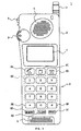
- Fig. 1 denotes a portable telephone device according to this invention as a whole, and various members are installed on a body case 2 made of synthetic resin materials.
- An antenna 3 for transmittance and reception which can be extended and retracted is installed on the top of the body case 2.
- the portable telephone device 1 transmits and receives radio waves between a base station apparatus and itself through the antenna 3.
- a power switch 4 is provided on the side of the body case 2.
- the power switch 4 is turned on to supply electric current from a battery pack (not shown) installed on the back of the body case 2 to each of electric circuits, and is started up to be in an operable state as a portable telephone device.
- a speaker 5 is provided at the upper part on the front of the body case 2 as electricity-to-sound converting means.
- the call partner's voice is output from the speaker 5 during a call.
- a microphone 6 is provided at the lowest part on the front of the body case 2 as sound-to-electricity converting means. The user's voice is collected from the microphone 6 during a call.
- a liquid crystal display (LCD) 7 is provided at the middle part on the front of the body case 2 as display means.
- the LCD 7 displays various information such as reception state of radio waves, battery capacity, telephone number when making a telephone call, telephone numbers and the names of the partners registered as a telephone directory, information of sent history, and information of various registered contents.
- various operation keys 8 are provided at the lower part on the front of the body case 2 as operation means.
- the operation keys 8 are used to input various directions.
- following nine keys are provided as the operation keys 8 concretely.
- the nine keys are: “phone” key 8A, " end” key 8B, "redial” key 8C, "0" to “9” numeral keys 8D, "*" key 8E, "#” key 8F, "memory” key 8G, "clear” key 8H, and "read” key 8I.
- a function for inputting a direction to phone at the input telephone number, the telephone number read from a telephone directory, or the telephone number read from the sent history is assigned to the "phone" key 8A.
- a function for inputting a direction to finish a talking and for inputting a direction to finish other various operation mode is assigned to the "end” key 8B.
- a function for inputting a direction to read the sent history that the telephone numbers of the partners who are telephoned by an user are displayed together with the date and time is assigned to the "redial" key 8C.
- Functions for inputting corresponding numeral information are respectively assigned to ten numeral keys 8D.
- a function for inputting "*(asterisk)" character is assigned to "*" key 8E.
- a function for inputting "#" character is assigned to "#” key 8F.
- a function for inputting a direction to register a telephone number as a telephone directory is assigned to "memory" key 8G.
- a function for inputting a direction to delete the displayed contents or registered contents is assigned to "clear” key 8H.
- a function for inputting a direction to read the telephone number registered as a telephone directory is assigned to "read" key 8I.
- a jog dial 9 is provided at the upper part on the side of the body case 2 as a rotary operation key.
- the jog dial 9 is rotated to scroll and display various display items such as the sent history list or the telephone directory list displayed on the liquid crystal display 7.
- the jog dial 9 is pushed into the inner direction of the body case 2 to determine the item being displayed.
- the jog dial 9 can be also pushed into the depth direction (perpendicular to Fig. 1) along the side of the body case 2.
- the jog dial 9 is rotated with being pushed into the depth direction to scroll and display the display items with another movement amount.
- a function for inputting a direction to phone and a function as a function key are also assigned to the pushing operation of the jog dial 9 in the inner direction.
- desired characters can be input by the operation of the jog dial 9 to make the telephone directory list.
- the body case 2 of the portable telephone device 1 is provided with circuits as shown in Fig. 2.
- the directed information input from various operation keys 8 or the jog dial 9 described above is firstly input to a CPU (Central Processing Unit) 10 which is control means.
- the CPU 10 controls a LCD driver circuit 7A based on the input directed information to display various information in accordance with the directed information (e.g., input telephone number, menu items, sent history, or telephone directory) on the liquid crystal display 7.
- the CPU 10 further controls a transmitter/receiver circuit part 11 based on the input directed information to execute such processing in accordance with the directed information as phone processing and end processing.
- the CPU 10 accesses a RAM (Random Access Memory) 12 which is a first storing means to store a predetermined information, or accesses an EEPROM (Electrically Erasable and Programmable Read Only Memory) 13 which is a second storing means to store various information which are desired to be maintained after the power is shut-off, such as the sent history and the telephone directory list.
- a RAM Random Access Memory
- EEPROM Electrical Erasable and Programmable Read Only Memory
- the transmitter/receiver circuit 11 outputs a control signal by the control from the CPU 10 through the antenna 3 to perform a phone processing, or receives a received signal from the base station apparatus through the antenna 3 to inform a reception of the CPU 10.
- the transmitter/receiver circuit 11 further performs a predetermined signal processing on an audio signal input from the microphone 6 to transmit it during a call, or performs a predetermined signal processing on a received signal to demodulate the audio signal, which is outputs to the speaker 5.
- the jog dial 9 is composed of a disc member 20, a detecting circuit 21, and a first and second switches 22, 23.
- the detecting circuit 21 detects the rotating direction and the rotated amount, and this is informed of the CPU 10.
- the first switch 22 is pushed, and when the disc member 20 is pushed in the depth direction along the side, the second switch 23 is pushed.
- the CPU 10 detects the condition of the first and second switches 22, 23.
- the CPU 10 thereby controls various operations of the jog dial 9 described above based on the condition of the first and second switches 22, 23 and based on the rotating direction and the rotated amount from the detecting circuit 21.
- the jog dial 9 is provided at the upper part on the left side of the body case 2, and is rightly positioned at the left hand's thumb position when an user holds the body 2 with the left hand. Thereby, even in the state of holding the body 2, the user can rotate the jog dial 9 by bending and extending the left hand's thumb, and push the jog dial 9 by pressing the left hand's thumb into the inner direction of the body case 2, and further push the jog dial 9 into the depth direction by slightly sliding the left hand's thumb into the depth direction along the side of the body case 2. In this way, the user can operate the jog dial 9 with one hand easily.
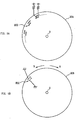
- the jog dial 9 has the disc member 20 as described above. As shown in Fig. 3, the disc member 20 is slightly projected from the side of the body case 2, so that the thumb can be put on the projection to rotate it, to push it in the inner direction of the body case 2, and to push it in the depth direction along the side.
- the disc member 20 is supported by a base part 25 made of synthetic resin materials in such a way that it can rotate in the direction shown by an arrow "A" or "B” with a rotation axis "O" being centered.
- the thumb is put on the projection to rotate the disc member 20 in the direction of the arrow "A" or "B".
- the sensation of click can be obtained.
- an user can understand sensuously the rotated amount of the disc member 20 (hereinafter, the rotated amount which can obtain the sensation of click is referred to as one click).
- the disc member 20 is not directly supported on the base part 25, but supported on the base part 25 through a slide member 26.
- the disc member 20 thereby moves in the direction shown by an arrow "D” when it is pushed in the inner direction of the body case 2 by the thumb.
- the disc member 20 is pressed in the direction shown by an arrow "C” by the slide member 26, so as to keep the disc member 20 being slightly projected from the body case 2 as shown in Fig. 3 while the disc member 20 is not pushed into the inner direction of the case (that is, in the direction of the arrow "D").
- a clamp member 27 and the first switch 22 are also provided on the base part 25.
- the clamp member 27 rotates in the direction shown by an arrow "F” with a fulcrum “E” being centered, when the disc member 20 moves in the direction shown by the arrow “D".
- a projection 27A projecting below is provided on the top of the clamp member 27. When the projection 27A rotates in the direction of the arrow "F” with the fulcrum "E” being centered, it reaches the top side of the first switch 22 as shown in Figs. 4A and 4B. In the jog dial 9, when the disc member 20 is pushed in the direction of the arrow "D", the projection 27A presses the first switch 22.
- the disc member 20 is composed of two disc members 20A and 20B actually.
- the disc member 20B is a movable member placed on the upper side of the disc member 20A, and is installed to rotate relatively to the fixed disc member 20A.
- a pair of electrodes 20C is provided on the movable disc member 20B.
- the electrodes 20C comes in contact with twenty pairs of electrodes 20D provided along the circumference of the disc member 20A when it is assembled.
- the electrodes 20D provided on the fixed disc member 20A is so formed that they are slightly shifted between the inner and the outer.
- the detecting circuit 21 uses this to detect which of the inner potential or the outer potential falls to the ground potential first, so as to detect the rotating direction of the disc member 20B. Further, the detecting circuit 21 counts up the number of pulses output from the outer electrode, so as to detect the rotated amount of the disc member 20B.
- the base part 25 in which the disc member 20 is installed is hooked and supported by a hook part 2A provided inside the body case 2 so as to be installed in the body case 2.
- the projection 25A is provided under the base part 25, and the base part 25 is supported by the projection 25A from below.
- the second switch 23 is provided slightly apart from the base part 25. In this case, since the base part 25 is supported from below by the projection 25A, when the disc member 20 is pushed in the depth direction shown by an arrow "G", the base part 25 is bent downward in the direction shown by the arrow "G" with the projection 25A being a fulcrum.
- the bottom side of the base part 25 bent downward comes into contact with the second switch 23 and presses the second switch 23.
- the base part 25 in which the disc member 20 is installed is bent so as to press the second switch 23.
- a supporting member 25B is provided and an arm member 25C is provided through the supporting member 25B.
- the arm member 25C is provided over one portion of the disc member 20.
- the typical operation examples using the jog dial 9 will be explained.
- the cursor displayed on the liquid crystal display 7 can be moved up or down.
- the jog dial 9 is pushed toward the inner direction of the body case 2 in this state, so as to make it possible to direct the CPU 10 to read the detailed information relating to the item where the cursor is positioned and the lower hierarchical items.
- the cursor can be moved up or down.
- the jog dial 9 is pushed in the inner direction of the body case 2 in the state that the cursor is matched with a desired partner, so as to phone the partner.
- the cursor can be moved up and down, or left and right. Then, the jog dial 9 is pushed in the inner direction of the body case 2 in the state that the cursor is matched with a desired character, so as to input the character.
- the jog dial 9 is rotated in the state that a registration mode is set, an user can enter the registration mode of an arbitrary item. Then, the jog dial 9 is pushed in the inner direction of the body case 2 or pushed in the depth direction along the side in this state, so as to direct to select or determine the registered content.
- the telephone directory list is scrolled for one line upward.
- the partner's names registered in the abbreviated dialing "002" and “003" are displayed in the order of number, and at the same time the partner's name registered in the abbreviated dialing "004" is newly displayed on the third line.
- the cursor K1 is also displayed at the center of the telephone directory list similarly, so that the partner of the abbreviated dialing "003" is being selected in this state.
- the cursor may be moved back one line from the current selection and the jog dial 9 is rotated for one click upward in this state. As shown in Fig. 8E, the telephone directory list is scrolled for one line downward by this operation, so that the cursor K1 can be displayed at the desired partner to select
- the jog dial 9 is pushed in the inner direction of the body case to determine the partner, and as shown in Fig. 8F, the detailed information of the selected that is the telephone number, can be displayed.
- the portable telephone device 1 phones the partner whose telephone number is being displayed (i.e., the displayed telephone number is transmitted to the base station apparatus through the transmitter/receiver circuit part 11 to connect the communication line). The user can phone in the state of touching the jog dial 9 without the operation of the "phone" key 8A.
- the push of jog dial 9 in the depth direction is assigned to the change of the scrolling amount (i.e., the change of the amount that a cursor moves).
- the movement amount of cursor is changed from one line to ten lines, so that the desired partner can be found quickly.
- the partner registered at the abbreviated dialing "050" is desired to be found in the state that the abbreviated dialing "001" is being currently selected
- the jog dial 9 is rotated for five clicks downward while pushing it in the depth direction, so that the desired partner can be found.
- the desired partner can be found quickly comparing to the conventional operation in which the user must rotate it for fifty clicks.
- the character input using the jog dial 9 will be explained with referring to Fig. 9.
- the Kana characters can be input to register a partner's name, and at the same time, the input Kana characters can be converted into the Kanji characters when the Kanji converting mode is set.
- the jog dial 9 is first pushed in the inner direction of the body case in the state that a call is not made, to read the menu prepared in the portable telephone device 1. Then, the jog dial 9 is rotated in a predetermined direction to find the character input mode among from the menu items (that is the jog dial 9 is rotated to display the cursor K1 at the item of the character input mode). In this state, the jog dial 9 is pushed in the inner direction similarly to set the character input mode.
- the character input mode picture shown in Fig. 9A is displayed on the liquid crystal display 7 by this setting operation.
- the Kanji converting mode is previously set by a predetermined operation
- representing that the Kanji converting mode is set is displayed at the top portion on the initial picture of the character input mode.
- the input character mark ">>>:” is displayed in the second line on the initial picture and the Kana characters input by the operation described below are successively displayed after the input character mark.
- the Kana characters of line and line of the Japanese syllabary are displayed one line below the mark
- the Kana characters of line and line of the Japanese syllabary are displayed one line further below the mark.
- the characters of are virtually prepared further below them, although they are not displayed in this state.
- the cursor K1 is firstly displayed at the Kana character and that character is being selected.
- the jog dial 9 is first rotated for one click downward. As shown in Fig. 9B, the cursor K1 is moved downward for one line and is displayed at the Kana character which is being selected. When the jog dial 9 is then rotated for one click upward while pushing it in the depth direction, the movement direction of the cursor K1 by the rotation is changed. As a result, as shown in Fig. 9C, the cursor K1 is moved in the right direction for one character and is displayed at the Kana character which is being selected.
- the jog dial 9 is rotated for one click downward without pushing it in the depth direction to change the movement direction of the cursor K1 according to the rotation of the jog dial 9 into the down direction again.
- the cursor K1 is moved downward for one line to be displayed at the Kana character which is being selected.
- the position where the cursor K1 is displayed on the picture is not changed, and the table of the Japanese syllabary is scrolled upward for one line as a whole so that the cursor K1 is visually moved downward for one line.
- the jog dial 9 is then pushed in the inner direction of the body case to determine the character as shown in Fig. 9E and the determined Kana character is displayed after the input character mark. Thereafter, desired characters are successively selected and determined by the same operation of the jog dial 9 described above, and a predetermined operation keys 8 is used to input the Kanji converting direction to display the Kanji corresponding to the input Kana characters. Thereby, the desired characters can be input with the Kanji.
- the push of the jog dial 9 in the depth direction is assigned to the change of the cursor movement direction.
- the jog dial 9 is simply rotated upward or downward to move the cursor K1 up or down, and the jog dial 9 is rotated upward or downward while pushing it in the depth direction to move the cursor K1 in the right or left direction.
- the cursor quickly reaches a desired character and an user can input a character quickly comparing to the conventional one.
- the cursor is only moved in the right or left direction simply.
- the pushing in the depth direction is prepared in the jog dial 9 to change the movement direction of the cursor K1 by pushing the jog dial 9 in the depth direction, so that the cursor K1 can be moved in the lines direction and the columns direction in the table of the Japanese syllabary and the desired character can be selected and input quickly.
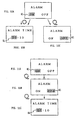
- the jog dial 9 is first pushed in the inner direction of the body case in the state that a call is not made to read out the menu prepared in the portable telephone device 1. Then, the jog dial 9 is rotated in a predetermined direction to find the alarm setting mode from the menu items (that is, the jog dial 9 is rotated to display the cursor K1 at the item of the alarm setting mode). In this state, the jog dial 9 is similarly pushed in the inner direction to set the alarm setting mode. As shown in Fig. 10A, the alarm setting mode picture is displayed on the liquid crystal display 7 by this setting operation.
- the characters “alarm” representing the alarm setting mode is displayed in the first line to show an user the alarm setting mode.
- the alarm setting mode is provided with the alarm starting and non-starting functions, and "ON" and “OFF” representing them are displayed in the second line.
- the cursor K1 is initially displayed at "ON" position and the alarm starting is being selected.
- the push of the jog dial 9 in the depth direction is assigned to the determination of the item where the cursor K1 is displayed;
- the push of the jog dial 9 in the inner direction of the body case is assigned to the movement of the cursor K1 in the right direction (after the cursor reaches the end of the line, it moves to the head of the line or the next line, and moves in the right direction similarly), that is the selection of the item;
- the rotation of the jog dial 9 is assigned to the change of the mode from the operation mode into the menu item selecting mode of the upper hierarchy (when the jog dial is rotated upward, the cursor K1 moves to the menu item above the menu item currently read, and when it is rotated downward, the cursor K1 moves to the menu item below the menu item currently read).
- the jog dial 9 is pushed in the depth direction to set the alarm to a starting condition.
- the picture proceeds to the time setting picture for setting the alarm starting time.
- the cursor K1 is displayed at the position of "hour”, and the "numeral” key 8D is used to input a desired numeral in this state.
- the cursor K1 automatically moves to the position of "minute”, and the "numeral” key 8D is similarly used to input a desired numeral. In this way, the time to start the alarm can be input.
- the jog dial 9 is pushed in the inner direction of the body case to set the alarm to a non-starting condition.
- the cursor K1 moves in the right direction to be displayed at the position of "OFF”, and the jog dial 9 is pushed in the depth direction in this state so as to set the alarm to a non-starting condition.
- the push of the jog dial 9 in the inner direction of the body case is assigned to the selection of the item, and the push of the jog dial 9 in the depth direction is assigned to the determination of the item.
- the jog dial 9 is pushed in the inner direction of the body case to move the cursor K1, and further it is pushed in the depth direction to determine the item where the cursor K1 is displayed.
- the selection and determination of the item can not be separately performed to set the operation mode.
- the jog dial is pushed in the inner direction of the body case to set the alarm to a non-starting condition once, thereafter the jog dial must be pushed in the inner direction of the body case again to move the cursor K1 to the position of "ON". Two times operations are necessary to set the alarm to a starting condition.
- the selection and determination can be performed separately to set the operation mode, and the alarm can be set by one time operation so as to perform the setting quickly.
- the first switch 22 pushed when the jog dial 9 is pushed in the inner direction of the body case and the second switch 23 pushed when the jog dial 9 is pushed in the depth direction are provided so as to add two pushing operations in addition to the rotation operation, so that the operations in three directions can be performed.
- the jog dial 9 since the jog dial 9 is provided on the left side of the body case and at the home position of the thumb when the body case is held, the jog dial 9 can be operated with the thumb easily in the state that the body case 2 is held with one hand.
- the slide operation in the depth direction of the body case 2 is selected from the slide operations along the side of the thumb, so that this operation also can be performed easily.
- the pushing operation in the depth direction newly added is used to perform the retrieval of the telephone directory list quickly. More specifically, when the jog dial 9 is simply rotated in a desired direction, one click rotation moves the cursor for one line. However, when the jog dial 9 is rotated in a desired direction while pushing in the depth direction, one click rotation moves the cursor for ten lines. Thereby, even when a desired partner is distant from the current position, these operations are combined to reach at the desired partner quickly, thereby the retrieval of the telephone directory list can be performed quickly. Also, the jog dial 9 is unnecessary to be moved many times like a conventional one so that the operational efficiency in retrieval can be improved.
- the jog dial 9 in the character input mode, is rotated in a desired direction to move the cursor K1 upward or downward, and the jog dial 9 is rotated while pushing in the depth direction to move the cursor K1 right or left.
- the cursor K1 can be moved in the lines direction or in the columns direction in the table of the Japanese syllabary, so that the cursor can reach at the desired character quickly and the character can be input quickly comparing to the conventional one.
- the cursor K1 can be moved in the lines direction or in the columns direction, so that the rotating amount of the jog dial 9 to reach at the desired character can be reduced and the operational efficiency in inputting a character can be improved.
- the jog dial 9 when the jog dial 9 is rotated to move the cursor K1, the jog dial 9 is pushed in the depth direction to change the movement amount or the movement direction of the cursor K1.
- the cursor K1 can be moved quickly comparing to the conventional one and the operational efficiency and the usability can be improved remarkably.
- the push of the jog dial 9 in the inner direction of the body case is assigned to the selection of the item, and the push of the jog dial 9 in the depth direction is assigned to the determination of the item.
- the push operation in the depth direction is added as the push operation of the jog dial 9 to change the movement amount or the movement direction of the cursor K1, so that the cursor can reach at the desired partner quickly comparing to the conventional one and the operational efficiency and the usability can be improved remarkably.
- the push operation in the depth direction is added as the push operation of the jog dial 9 to perform the selection and determination of the item independently in setting the operation mode, so that the operational efficiency and the usability can be improved remarkably comparing to the conventional one. Therefore, the portable telephone device 1 which has the remarkably superior operational efficiency and the improved usability comparing to the conventional one can be realized.
- the above described embodiment has been dealt with a case where when the jog dial 9 is rotated upward or downward while pushing it in the depth direction, the cursor K1 is moved for ten lines.
- the present invention is not limited to this, but the cursor K1 can be moved for other movement amount.
- the above described embodiment has been dealt with a case where the jog dial 9 is rotated and simultaneously pushed in the depth direction to change the movement amount of the cursor K1 into ten lines.
- the present invention is not limited to this, but after the jog dial 9 is pushed in the depth direction, the movement amount of the cursor K1 can be changed into ten lines. In short, if the movement amount of the cursor K1 is changed by pushing the jog dial 9 in the depth direction, the same effect as described above can be obtained.
- the above described embodiment has been dealt with a case where the jog dial 9 is rotated and simultaneously pushed in the depth direction to change the movement direction of the cursor K1 into the right and left direction.
- the present invention is not limited to this, but after the jog dial 9 is pushed in the depth direction, the movement direction of the cursor K1 can be changed into the right and left direction. In short, if the movement direction of the cursor K1 is changed by pushing the jog dial 9 in the depth direction, the same effect as described above can be obtained.
- the above described embodiment has been dealt with a case where this invention is applied to a portable telephone device.
- the present invention is not limited to this, but can be widely applied to other electrical devices which display a cursor to select the item.
- the above described embodiment has been dealt with a case where when the retrieval of the telephone directory list or the character input mode, the jog dial 9 is pushed in the depth direction to change the movement direction or the movement amount of the cursor K1.
- the present invention is not limited to this, but this is applicable in other operation mode.
- the device is provided with: a body case having the outward shape which is held with one hand in the state that the thumb or the base of the thumb is put on one side of it; an operation key, which has a disc member wherein a projection being a part of the outer of the disc member slightly projected from the one side to the outside is provided at the position where the thumb is put on the one side of the body case so that the projection comes into contact with the thumb rotatively, for supporting the disc member in such a way that the disc member rotates when the thumb is bent and extended to rub the one side to give the rotative power to the disc member, or in such a way that the disc member moves in the pushed direction when the thumb is pushed into the inside of the one side to give the push power toward the inner of the body case to the disc member, or in such a way that the disc member moves in the depth direction when the thumb is slid on the one side to give the strength toward the depth direction of the body case to the disc member; operation detecting
- the above described embodiment has been dealt with a case where when setting the operation mode, two push operations of the jog dial 9 is assigned to the selection and determination.
- the present invention is not limited to this, but this is applicable in other operation mode.
- the same effect described above can be obtained, if the device is provided with: a body case having the outward shape which is held with one hand in the state that the thumb or the base of the thumb is put on one side of it; an operation key, which has a disc member wherein a projection being a part of the outer of the disc member slightly projected from the one side to the outside is provided at the position where the thumb is put on the one side of the body case so that the projection comes into contact with the thumb rotatively, for supporting the disc member in such a way that the disc member rotates when the thumb is bent and extended to rub the one side to give the rotative power to the disc member, or in such a way that the disc member moves in the pushed direction when the thumb is pushed into the inside of the one side to give the push power
- the above described embodiment has been dealt with a case where the disc member 20 is supported on the base part 25 through the slide member 26.
- the present invention is not limited to this, but other constitution can be applied, if the supporting member is such a member that rotates the disc member, moves it in the inner direction of the body case, and moves it in the depth direction of the body case.
- the electronic device can be improved in the operation efficiency and the usability, since the rotary operation key can be operated in three directions in the state that the body case is held with one hand, if the rotary operation key provided in the body case of the electronic device which includes the body case having the outward shape held with one hand in the state that the thumb or the base of the thumb is put on one side of it, the rotary operation key is provided with: a disc member wherein a projection being a part of the outer of the disc member slightly projected from the one side to the outside is provided at the position where the thumb is put on the one side of the body case so that the projection comes into contact with the thumb rotatively; and supporting means for supporting the disc member in such a way that the disc member rotates when the thumb is bent and extended to rub the one side to give the rotative power to the disc member, or in such a way that the disc member moves in the pushed direction when the thumb is pushed into the inside of the one side to give the push power toward the inner of the body case to the disc member, or in
- a communication terminal device and a rotary operation key according to the present invention are applied a portable telephone device which executes various operations using, for example, a rotary operation key.
Landscapes
- Engineering & Computer Science (AREA)
- Signal Processing (AREA)
- Telephone Function (AREA)
- Input From Keyboards Or The Like (AREA)
- Telephone Set Structure (AREA)
- User Interface Of Digital Computer (AREA)
Applications Claiming Priority (3)
| Application Number | Priority Date | Filing Date | Title |
|---|---|---|---|
| JP34374897A JP3865169B2 (ja) | 1997-11-28 | 1997-11-28 | 通信端末装置及び通信端末装置の制御方法 |
| JP34374897 | 1997-11-28 | ||
| PCT/JP1998/005360 WO1999029087A1 (fr) | 1997-11-28 | 1998-11-27 | Terminal de telecommunications et bouton de commande rotatif |
Publications (2)
| Publication Number | Publication Date |
|---|---|
| EP0961461A1 true EP0961461A1 (fr) | 1999-12-01 |
| EP0961461A4 EP0961461A4 (fr) | 2003-08-27 |
Family
ID=18363939
Family Applications (1)
| Application Number | Title | Priority Date | Filing Date |
|---|---|---|---|
| EP98955974A Withdrawn EP0961461A4 (fr) | 1997-11-28 | 1998-11-27 | Terminal de telecommunications et bouton de commande rotatif |
Country Status (6)
| Country | Link |
|---|---|
| US (1) | US6546231B1 (fr) |
| EP (1) | EP0961461A4 (fr) |
| JP (1) | JP3865169B2 (fr) |
| KR (1) | KR20000070132A (fr) |
| CN (1) | CN1148086C (fr) |
| WO (1) | WO1999029087A1 (fr) |
Cited By (12)
| Publication number | Priority date | Publication date | Assignee | Title |
|---|---|---|---|---|
| EP1111879A1 (fr) * | 1999-12-21 | 2001-06-27 | Sony International (Europe) GmbH | Appareil de communication portatif avec des moyens de défilement à travers une matrice bidimensionnelle de caractères |
| EP1150243A3 (fr) * | 2000-04-27 | 2004-02-04 | Sony Corporation | Commutateur actionné par rotation et terminal de communication |
| EP1387559A1 (fr) * | 2002-07-31 | 2004-02-04 | Fujitsu Limited | Terminal de traitement de données et procédé de commande |
| GB2413920A (en) * | 2004-04-30 | 2005-11-09 | Motorola Inc | Mobile station with multi-position sliding actuator for function control |
| US6968164B2 (en) | 2003-05-19 | 2005-11-22 | Visteon Global Technologies, Inc. | Method of controlling filter bandwidth in a radio receiver for a duplicative broadcast signal |
| EP1724996A3 (fr) * | 2005-05-16 | 2007-02-07 | LG Electronics Inc. | Terminal mobile avec un dispositif de défilement et un procédé l'utilisant |
| EP1755319A3 (fr) * | 1999-12-16 | 2007-02-28 | Koninklijke Philips Electronics N.V. | Interface utilisateur avec rétroaction auditive pour un dispositif tenu a la main |
| EP1271904A3 (fr) * | 2001-06-21 | 2007-05-30 | Lg Electronics Inc. | Terminal de communication mobile et méthode d'opération associée |
| WO2008039563A1 (fr) * | 2006-09-29 | 2008-04-03 | Sony Ericsson Mobile Communications Ab | Molette peu encombrante de type 'jog dial' pour un terminal mobile |
| US7405728B2 (en) * | 2002-07-02 | 2008-07-29 | Sony Corporation | Portable information terminal, program, and recording medium having the program recorded therein |
| US8160649B2 (en) | 2006-03-31 | 2012-04-17 | Research In Motion Limited | Initiating a call from a mobile device to a number that is not hyperlinked |
| EP2086117A3 (fr) * | 2008-02-04 | 2012-07-25 | Hytera Communications Corp., Ltd. | Radio dotée d'une combinaison de touches et de boutons |
Families Citing this family (79)
| Publication number | Priority date | Publication date | Assignee | Title |
|---|---|---|---|---|
| KR20010068805A (ko) * | 2000-01-10 | 2001-07-23 | 윤종용 | 죠그 다이얼을 이용한 단축 다이얼링 수행방법과 선택메뉴 기능설명 메세지 송출방법 |
| AU2001253161A1 (en) * | 2000-04-04 | 2001-10-15 | Stick Networks, Inc. | Method and apparatus for scheduling presentation of digital content on a personal communication device |
| JP4385490B2 (ja) * | 2000-05-12 | 2009-12-16 | ソニー株式会社 | 携帯端末装置 |
| JP4487399B2 (ja) * | 2000-09-06 | 2010-06-23 | ソニー株式会社 | 情報処理装置 |
| US7636079B2 (en) * | 2000-11-29 | 2009-12-22 | Palm Inc. | Application access and activation system and method |
| TW486621B (en) * | 2000-11-30 | 2002-05-11 | Primax Electronics Ltd | Encoding module applicable to graphics user interface signal input device |
| US7458080B2 (en) * | 2000-12-19 | 2008-11-25 | Microsoft Corporation | System and method for optimizing user notifications for small computer devices |
| DE10118015A1 (de) * | 2001-04-10 | 2002-10-24 | Cimosys Ag Goldingen | Elektromotorischer Möbelantrieb zum Verstellen von Teilen eines Möbels relativ zueinander |
| JP2002319330A (ja) | 2001-04-20 | 2002-10-31 | Mitsubishi Electric Corp | スイッチ装置および携帯電話機 |
| JP2003069692A (ja) * | 2001-08-22 | 2003-03-07 | Nec Infrontia Corp | 電話帳共有方法、電話帳データ登録/引出し方法、および同プログラム |
| JP3876671B2 (ja) * | 2001-09-26 | 2007-02-07 | ティアック株式会社 | 入力装置およびこれを備える情報処理装置ならびにカーソル表示制御方法 |
| US7120473B1 (en) * | 2001-10-14 | 2006-10-10 | Palm, Inc. | Method and apparatus for controlling a mobile device by using a pivoting input switch |
| US7312785B2 (en) * | 2001-10-22 | 2007-12-25 | Apple Inc. | Method and apparatus for accelerated scrolling |
| US7345671B2 (en) * | 2001-10-22 | 2008-03-18 | Apple Inc. | Method and apparatus for use of rotational user inputs |
| US6775380B2 (en) * | 2001-11-27 | 2004-08-10 | Shin Jiuh Corp. | Switch capable of generating voices in response to a pressing action |
| US7333092B2 (en) | 2002-02-25 | 2008-02-19 | Apple Computer, Inc. | Touch pad for handheld device |
| KR100488971B1 (ko) * | 2002-09-11 | 2005-05-11 | 현대모비스 주식회사 | 텔레메틱스 단말기에서의 문자 입력 장치 및 방법 |
| FI20021759A0 (fi) * | 2002-10-03 | 2002-10-03 | Nokia Corp | Menetelmä ja käyttöliittymä tekstin syöttämiseen |
| KR100524734B1 (ko) * | 2002-11-18 | 2005-10-31 | 엘지전자 주식회사 | 휴대용 단말기의 다기능 측면 버튼 조립체 |
| KR100617681B1 (ko) | 2003-04-15 | 2006-08-28 | 삼성전자주식회사 | 휴대용 단말기의 회전키 장치 사용 방법 |
| US7856251B2 (en) | 2003-04-24 | 2010-12-21 | Samsung Electronics Co., Ltd. | Device and method for using a rotating key and controlling a display in a mobile terminal |
| US7263380B2 (en) * | 2003-04-28 | 2007-08-28 | Sony Ericsson Mobile Communications Ab | Method and device for scrolling speed control |
| US20040253989A1 (en) * | 2003-06-12 | 2004-12-16 | Tupler Amy M. | Radio communication device having a navigational wheel |
| US7499040B2 (en) | 2003-08-18 | 2009-03-03 | Apple Inc. | Movable touch pad with added functionality |
| US20070152977A1 (en) | 2005-12-30 | 2007-07-05 | Apple Computer, Inc. | Illuminated touchpad |
| US7440767B2 (en) * | 2003-10-15 | 2008-10-21 | Eaton Corporation | Home system including a portable fob having a rotary menu and a display |
| US7495659B2 (en) | 2003-11-25 | 2009-02-24 | Apple Inc. | Touch pad for handheld device |
| US8059099B2 (en) | 2006-06-02 | 2011-11-15 | Apple Inc. | Techniques for interactive input to portable electronic devices |
| EP1536315A1 (fr) * | 2003-11-27 | 2005-06-01 | Sony NetServices GmbH | Dispositif d'accès à des informations |
| KR100754687B1 (ko) * | 2003-12-12 | 2007-09-03 | 삼성전자주식회사 | 휴대단말기의 멀티입력부 및 그의 제어방법 |
| JP4311254B2 (ja) * | 2004-03-31 | 2009-08-12 | 日本電気株式会社 | 携帯型電子機器 |
| TWM257497U (en) * | 2004-05-19 | 2005-02-21 | Lite On Technology Corp | Use roller of cell phone input apparatus |
| EP1773037A1 (fr) * | 2004-05-28 | 2007-04-11 | Research In Motion Limited | Procédé et interface utilisateur permettant de déclencher un appel à un numéro de téléphone contenu dans un message reçu par une station mobile |
| JP3925519B2 (ja) * | 2004-08-02 | 2007-06-06 | 松下電器産業株式会社 | 折畳回動式携帯端末装置 |
| KR100927064B1 (ko) | 2004-08-16 | 2009-11-13 | 애플 인크. | 터치 감지 장치의 공간 해상도를 증가시키는 방법 |
| US7808477B2 (en) * | 2005-01-04 | 2010-10-05 | Microsoft Corporation | Scroll disc input apparatus for a data processing device |
| US7551186B2 (en) * | 2005-02-22 | 2009-06-23 | Eaton Corporation | Handheld electronic device, system and method for inverting display orientation for left-handed or right-handed operation responsive to a wireless message |
| JP4498174B2 (ja) * | 2005-03-08 | 2010-07-07 | キヤノン株式会社 | 像域情報生成装置、像域情報生成方法およびプログラム |
| US20060258390A1 (en) * | 2005-05-12 | 2006-11-16 | Yanqing Cui | Mobile communication terminal, system and method |
| US7671837B2 (en) * | 2005-09-06 | 2010-03-02 | Apple Inc. | Scrolling input arrangements using capacitive sensors on a flexible membrane |
| US7880729B2 (en) | 2005-10-11 | 2011-02-01 | Apple Inc. | Center button isolation ring |
| TWI290298B (en) * | 2005-11-11 | 2007-11-21 | Primax Electronics Ltd | Mouse with multi-function keys |
| USD545294S1 (en) * | 2005-12-20 | 2007-06-26 | Lg Electronics Inc. | Cellular phone |
| USD545293S1 (en) * | 2005-12-20 | 2007-06-26 | Lg Electronics, Inc. | Cellular phone |
| US20070152983A1 (en) | 2005-12-30 | 2007-07-05 | Apple Computer, Inc. | Touch pad with symbols based on mode |
| US7760184B2 (en) * | 2006-04-03 | 2010-07-20 | Nokia Corporation | Dual mode input device |
| DE102006016898A1 (de) * | 2006-04-11 | 2007-11-15 | Bayerische Motoren Werke Ag | Vorrichtung zur Steuerung der Bewegung eines Cursors |
| KR100743096B1 (ko) | 2006-05-11 | 2007-07-27 | 주식회사 팬택 | 버튼 구조 및 이를 포함하는 개인휴대단말기 |
| US7856254B2 (en) * | 2006-06-05 | 2010-12-21 | Lg Electronics Inc. | Mobile communication terminal and method of controlling the same |
| US8743060B2 (en) | 2006-07-06 | 2014-06-03 | Apple Inc. | Mutual capacitance touch sensing device |
| US8022935B2 (en) | 2006-07-06 | 2011-09-20 | Apple Inc. | Capacitance sensing electrode with integrated I/O mechanism |
| US9360967B2 (en) | 2006-07-06 | 2016-06-07 | Apple Inc. | Mutual capacitance touch sensing device |
| US7795553B2 (en) | 2006-09-11 | 2010-09-14 | Apple Inc. | Hybrid button |
| US20080088597A1 (en) * | 2006-10-11 | 2008-04-17 | Apple Inc. | Sensor configurations in a user input device |
| US8274479B2 (en) | 2006-10-11 | 2012-09-25 | Apple Inc. | Gimballed scroll wheel |
| US20080088600A1 (en) * | 2006-10-11 | 2008-04-17 | Apple Inc. | Method and apparatus for implementing multiple push buttons in a user input device |
| USD583783S1 (en) * | 2006-10-17 | 2008-12-30 | Sprint Spectrum L.P. | Phone |
| US8482530B2 (en) | 2006-11-13 | 2013-07-09 | Apple Inc. | Method of capacitively sensing finger position |
| CL2007002310S1 (es) * | 2007-02-15 | 2008-02-22 | Lg Electronics Inc | Telefono celular. |
| US8683378B2 (en) | 2007-09-04 | 2014-03-25 | Apple Inc. | Scrolling techniques for user interfaces |
| CN201315050Y (zh) | 2007-09-04 | 2009-09-23 | 苹果公司 | 紧凑输入装置 |
| US8416198B2 (en) | 2007-12-03 | 2013-04-09 | Apple Inc. | Multi-dimensional scroll wheel |
| US8125461B2 (en) | 2008-01-11 | 2012-02-28 | Apple Inc. | Dynamic input graphic display |
| US8820133B2 (en) | 2008-02-01 | 2014-09-02 | Apple Inc. | Co-extruded materials and methods |
| JP4521450B2 (ja) * | 2008-03-14 | 2010-08-11 | ホシデン株式会社 | 複合操作型入力装置 |
| US9454256B2 (en) * | 2008-03-14 | 2016-09-27 | Apple Inc. | Sensor configurations of an input device that are switchable based on mode |
| TWI375162B (en) | 2008-05-02 | 2012-10-21 | Hon Hai Prec Ind Co Ltd | Character input method and electronic system utilizing the same |
| EP2120116B1 (fr) * | 2008-05-11 | 2011-12-07 | Research In Motion Limited | Dispositif électronique et procédé fournissant une fonction réveil améliorée et alarme améliorée |
| KR20090131423A (ko) * | 2008-06-18 | 2009-12-29 | 삼성전자주식회사 | 문자 입력 장치 및 그 입력 방법 |
| US20100060568A1 (en) * | 2008-09-05 | 2010-03-11 | Apple Inc. | Curved surface input device with normalized capacitive sensing |
| US8816967B2 (en) * | 2008-09-25 | 2014-08-26 | Apple Inc. | Capacitive sensor having electrodes arranged on the substrate and the flex circuit |
| US8395590B2 (en) | 2008-12-17 | 2013-03-12 | Apple Inc. | Integrated contact switch and touch sensor elements |
| US9354751B2 (en) | 2009-05-15 | 2016-05-31 | Apple Inc. | Input device with optimized capacitive sensing |
| US8872771B2 (en) | 2009-07-07 | 2014-10-28 | Apple Inc. | Touch sensing device having conductive nodes |
| NZ589787A (en) * | 2010-12-08 | 2012-03-30 | S L I Systems Inc | A method for determining relevant search results |
| JP5973335B2 (ja) * | 2012-12-13 | 2016-08-23 | 京セラ株式会社 | 防水構造を有する電子機器 |
| JP2015176462A (ja) * | 2014-03-17 | 2015-10-05 | 祥司 鱒渕 | 操作装置 |
| CN104850322A (zh) * | 2015-05-05 | 2015-08-19 | 成都上生活网络科技有限公司 | 一种用户交互界面系统及实现方法 |
| CN114579008B (zh) * | 2022-05-06 | 2022-07-08 | 湖北工业大学 | 一种科普体验交互系统 |
Family Cites Families (17)
| Publication number | Priority date | Publication date | Assignee | Title |
|---|---|---|---|---|
| US4273971A (en) * | 1978-03-28 | 1981-06-16 | Lucas Industries Limited | Electrical switch having rotatable and pivotable lever |
| JP2508446Y2 (ja) * | 1991-10-17 | 1996-08-21 | エスエムケイ株式会社 | 複合動作スイッチ |
| US5835732A (en) * | 1993-10-28 | 1998-11-10 | Elonex Ip Holdings, Ltd. | Miniature digital assistant having enhanced host communication |
| JP3268467B2 (ja) * | 1992-09-08 | 2002-03-25 | 株式会社日立製作所 | 電話機 |
| DE4405962C1 (de) * | 1994-02-24 | 1995-06-01 | Loewe Opta Gmbh | Betätigungsvorrichtung für eine ortsfeste Bedienung an einem elektronischen Gerät oder an einem Fernbedienungsgeber hierfür |
| JP3067006B2 (ja) * | 1994-08-31 | 2000-07-17 | ソニー株式会社 | 通信端末装置 |
| FI118984B (fi) * | 1994-04-20 | 2008-05-30 | Sony Corp | Viestintäpäätelaite ja sen ohjausmenetelmä |
| KR960704397A (ko) * | 1994-05-17 | 1996-08-31 | 이데이 노부유끼 | 통신 단말 장치 및 휴대 전화 장치(Communication Terminal Apparatus and Portable Telephone Apparatus) |
| US6366771B1 (en) * | 1995-06-21 | 2002-04-02 | Arron S. Angle | Wireless communication network having voice and data communication capability |
| JP3508961B2 (ja) * | 1995-07-21 | 2004-03-22 | ソニー株式会社 | 端末装置 |
| US5966671A (en) * | 1996-01-03 | 1999-10-12 | Motorola, Inc. | Radiotelephone having an auxiliary actuator and method for operating said radiotelephone |
| US5931873A (en) * | 1996-10-04 | 1999-08-03 | Telxon Corporation | Programmable mobile device with thumb wheel |
| US6178338B1 (en) * | 1997-04-28 | 2001-01-23 | Sony Corporation | Communication terminal apparatus and method for selecting options using a dial shuttle |
| US6097964A (en) * | 1997-09-04 | 2000-08-01 | Nokia Mobile Phones Limited | Navigation key for a handset |
| US5923007A (en) * | 1997-10-15 | 1999-07-13 | Motorola, Inc. | Switch assembly including rocker switch with integrated center selector switch |
| JPH11184600A (ja) * | 1997-12-22 | 1999-07-09 | Sony Corp | 携帯情報端末装置、画面スクロール方法、記録媒体およびマイクロコンピュータ装置 |
| US5996790A (en) * | 1998-06-26 | 1999-12-07 | Asahi Research Corporation | Watertight equipment cover |
-
1997
- 1997-11-28 JP JP34374897A patent/JP3865169B2/ja not_active Expired - Fee Related
-
1998
- 1998-11-27 EP EP98955974A patent/EP0961461A4/fr not_active Withdrawn
- 1998-11-27 KR KR1019997006357A patent/KR20000070132A/ko not_active Ceased
- 1998-11-27 CN CNB988021099A patent/CN1148086C/zh not_active Expired - Fee Related
- 1998-11-27 WO PCT/JP1998/005360 patent/WO1999029087A1/fr not_active Ceased
- 1998-11-27 US US09/367,359 patent/US6546231B1/en not_active Expired - Fee Related
Cited By (21)
| Publication number | Priority date | Publication date | Assignee | Title |
|---|---|---|---|---|
| EP1755319A3 (fr) * | 1999-12-16 | 2007-02-28 | Koninklijke Philips Electronics N.V. | Interface utilisateur avec rétroaction auditive pour un dispositif tenu a la main |
| EP1111879A1 (fr) * | 1999-12-21 | 2001-06-27 | Sony International (Europe) GmbH | Appareil de communication portatif avec des moyens de défilement à travers une matrice bidimensionnelle de caractères |
| EP1150243A3 (fr) * | 2000-04-27 | 2004-02-04 | Sony Corporation | Commutateur actionné par rotation et terminal de communication |
| KR100753094B1 (ko) * | 2000-04-27 | 2007-08-31 | 소니 가부시끼 가이샤 | 회전조작스위치장치 및 통신단말장치 |
| US8903462B2 (en) | 2001-06-21 | 2014-12-02 | Lg Electronics Inc. | Folder type mobile telephone and operating method thereof |
| EP2259562A1 (fr) * | 2001-06-21 | 2010-12-08 | LG Electronics, Inc. | Terminal de communication mobile |
| US7583988B2 (en) | 2001-06-21 | 2009-09-01 | Lg Electronics Inc. | Folder type mobile telephone and operating method thereof |
| US8483766B2 (en) | 2001-06-21 | 2013-07-09 | Lg Electronics Inc. | Folder type mobile telephone and operating method thereof |
| EP1919175A1 (fr) | 2001-06-21 | 2008-05-07 | Lg Electronics Inc. | Terminal de communication mobile |
| EP1271904A3 (fr) * | 2001-06-21 | 2007-05-30 | Lg Electronics Inc. | Terminal de communication mobile et méthode d'opération associée |
| US7405728B2 (en) * | 2002-07-02 | 2008-07-29 | Sony Corporation | Portable information terminal, program, and recording medium having the program recorded therein |
| US7215761B2 (en) | 2002-07-31 | 2007-05-08 | Fujitsu Limited | Information processing terminal, operation content notifying program and method for operation content notifying |
| EP1387559A1 (fr) * | 2002-07-31 | 2004-02-04 | Fujitsu Limited | Terminal de traitement de données et procédé de commande |
| US6968164B2 (en) | 2003-05-19 | 2005-11-22 | Visteon Global Technologies, Inc. | Method of controlling filter bandwidth in a radio receiver for a duplicative broadcast signal |
| GB2413920A (en) * | 2004-04-30 | 2005-11-09 | Motorola Inc | Mobile station with multi-position sliding actuator for function control |
| EP1724996A3 (fr) * | 2005-05-16 | 2007-02-07 | LG Electronics Inc. | Terminal mobile avec un dispositif de défilement et un procédé l'utilisant |
| US8160649B2 (en) | 2006-03-31 | 2012-04-17 | Research In Motion Limited | Initiating a call from a mobile device to a number that is not hyperlinked |
| US8731617B2 (en) | 2006-03-31 | 2014-05-20 | Blackberry Limited | Initiating a call from a mobile device to a number that is not hyperlinked |
| WO2008039563A1 (fr) * | 2006-09-29 | 2008-04-03 | Sony Ericsson Mobile Communications Ab | Molette peu encombrante de type 'jog dial' pour un terminal mobile |
| RU2421774C2 (ru) * | 2006-09-29 | 2011-06-20 | Сони Эрикссон Мобайл Коммьюникейшнз Аб | Компактный поворотный выключатель для мобильного терминала |
| EP2086117A3 (fr) * | 2008-02-04 | 2012-07-25 | Hytera Communications Corp., Ltd. | Radio dotée d'une combinaison de touches et de boutons |
Also Published As
| Publication number | Publication date |
|---|---|
| KR20000070132A (ko) | 2000-11-25 |
| JPH11163997A (ja) | 1999-06-18 |
| EP0961461A4 (fr) | 2003-08-27 |
| US6546231B1 (en) | 2003-04-08 |
| JP3865169B2 (ja) | 2007-01-10 |
| CN1148086C (zh) | 2004-04-28 |
| WO1999029087A1 (fr) | 1999-06-10 |
| CN1246230A (zh) | 2000-03-01 |
Similar Documents
| Publication | Publication Date | Title |
|---|---|---|
| US6546231B1 (en) | Communication terminal device and rotary operation key | |
| JP3687811B2 (ja) | 通信端末装置及び発信履歴表示方法 | |
| JP3123990B2 (ja) | 携帯無線端末 | |
| JP4494533B2 (ja) | 通信端末装置及びダイヤルシャトルを用いたオプション選択方法 | |
| US7930002B2 (en) | Method for using multi-function key in a portable phone | |
| US20030011564A1 (en) | Portable information terminal | |
| KR100454865B1 (ko) | 휴대용통신장치 | |
| JPH07203019A (ja) | 押しボタンスイッチの機能を決定する方法およびそのためのアッセンブリ | |
| KR100334796B1 (ko) | 터치 스크린을 구비하는 이동통신 단말기의 키패드 장치 | |
| JP3067006B2 (ja) | 通信端末装置 | |
| JPH11146050A (ja) | 携帯無線機 | |
| JP2000112612A (ja) | 電子機器 | |
| JP2000115318A (ja) | 携帯電話機 | |
| JP3721527B2 (ja) | 情報端末装置及び電話帳表示発呼方法 | |
| JPH11112634A (ja) | 通信端末 | |
| KR20030030616A (ko) | 다이얼 수단이 구비된 이동통신 단말기 및 그 이동통신단말기에서의 다이얼링 방법 | |
| JPH1132113A (ja) | 携帯電話機 | |
| KR100806502B1 (ko) | 이동통신 단말기에서 문자 입력을 통한 기능별 메뉴 검색방법 | |
| JP3612475B2 (ja) | 表示制御装置 | |
| KR200369021Y1 (ko) | 포인터 입력이 가능한 이동 통신 단말기 | |
| KR20050028766A (ko) | 안테나를 이용한 입력 장치 | |
| KR20060012392A (ko) | 핫키를 갖는 이동 통신 단말기 및 그를 이용한 핫키 설정방법 | |
| KR20040041862A (ko) | 우선순위에 따른 휴대폰 전화번호부 검색 방법 | |
| KR940010850B1 (ko) | 다기능 무선전화기의 사용자기능 접근방법 | |
| KR20060019440A (ko) | 포인터 입력이 가능한 이동 통신 단말기 및 그 운용 방법 |
Legal Events
| Date | Code | Title | Description |
|---|---|---|---|
| PUAI | Public reference made under article 153(3) epc to a published international application that has entered the european phase |
Free format text: ORIGINAL CODE: 0009012 |
|
| 17P | Request for examination filed |
Effective date: 19990719 |
|
| AK | Designated contracting states |
Kind code of ref document: A1 Designated state(s): DE FI FR GB SE |
|
| A4 | Supplementary search report drawn up and despatched |
Effective date: 20030711 |
|
| 17Q | First examination report despatched |
Effective date: 20040608 |
|
| 17Q | First examination report despatched |
Effective date: 20040608 |
|
| STAA | Information on the status of an ep patent application or granted ep patent |
Free format text: STATUS: THE APPLICATION IS DEEMED TO BE WITHDRAWN |
|
| 18D | Application deemed to be withdrawn |
Effective date: 20060601 |