EP0962344A2 - Conduite de climatisation améliorée et son procédé de fabrication - Google Patents
Conduite de climatisation améliorée et son procédé de fabrication Download PDFInfo
- Publication number
- EP0962344A2 EP0962344A2 EP99303748A EP99303748A EP0962344A2 EP 0962344 A2 EP0962344 A2 EP 0962344A2 EP 99303748 A EP99303748 A EP 99303748A EP 99303748 A EP99303748 A EP 99303748A EP 0962344 A2 EP0962344 A2 EP 0962344A2
- Authority
- EP
- European Patent Office
- Prior art keywords
- conduit
- assembly
- collector
- fabric material
- exterior surface
- Prior art date
- Legal status (The legal status is an assumption and is not a legal conclusion. Google has not performed a legal analysis and makes no representation as to the accuracy of the status listed.)
- Withdrawn
Links
Images


Classifications
-
- B—PERFORMING OPERATIONS; TRANSPORTING
- B60—VEHICLES IN GENERAL
- B60H—ARRANGEMENTS OF HEATING, COOLING, VENTILATING OR OTHER AIR-TREATING DEVICES SPECIALLY ADAPTED FOR PASSENGER OR GOODS SPACES OF VEHICLES
- B60H1/00—Heating, cooling or ventilating devices
- B60H1/00507—Details, e.g. mounting arrangements, desaeration devices
- B60H1/00557—Details of ducts or cables
- B60H1/00564—Details of ducts or cables of air ducts
-
- B—PERFORMING OPERATIONS; TRANSPORTING
- B29—WORKING OF PLASTICS; WORKING OF SUBSTANCES IN A PLASTIC STATE IN GENERAL
- B29C—SHAPING OR JOINING OF PLASTICS; SHAPING OF MATERIAL IN A PLASTIC STATE, NOT OTHERWISE PROVIDED FOR; AFTER-TREATMENT OF THE SHAPED PRODUCTS, e.g. REPAIRING
- B29C49/00—Blow-moulding, i.e. blowing a preform or parison to a desired shape within a mould; Apparatus therefor
- B29C49/02—Combined blow-moulding and manufacture of the preform or the parison
- B29C49/04—Extrusion blow-moulding
- B29C49/0411—Means for defining the wall or layer thickness
-
- B—PERFORMING OPERATIONS; TRANSPORTING
- B29—WORKING OF PLASTICS; WORKING OF SUBSTANCES IN A PLASTIC STATE IN GENERAL
- B29C—SHAPING OR JOINING OF PLASTICS; SHAPING OF MATERIAL IN A PLASTIC STATE, NOT OTHERWISE PROVIDED FOR; AFTER-TREATMENT OF THE SHAPED PRODUCTS, e.g. REPAIRING
- B29C49/00—Blow-moulding, i.e. blowing a preform or parison to a desired shape within a mould; Apparatus therefor
- B29C49/24—Lining or labelling
-
- B—PERFORMING OPERATIONS; TRANSPORTING
- B60—VEHICLES IN GENERAL
- B60H—ARRANGEMENTS OF HEATING, COOLING, VENTILATING OR OTHER AIR-TREATING DEVICES SPECIALLY ADAPTED FOR PASSENGER OR GOODS SPACES OF VEHICLES
- B60H3/00—Other air-treating devices
- B60H3/02—Moistening ; Humidity control
- B60H3/024—Moistening ; Humidity control for only dehumidifying the air
-
- B—PERFORMING OPERATIONS; TRANSPORTING
- B29—WORKING OF PLASTICS; WORKING OF SUBSTANCES IN A PLASTIC STATE IN GENERAL
- B29L—INDEXING SCHEME ASSOCIATED WITH SUBCLASS B29C, RELATING TO PARTICULAR ARTICLES
- B29L2023/00—Tubular articles
- B29L2023/003—Tubular articles having irregular or rough surfaces
-
- Y—GENERAL TAGGING OF NEW TECHNOLOGICAL DEVELOPMENTS; GENERAL TAGGING OF CROSS-SECTIONAL TECHNOLOGIES SPANNING OVER SEVERAL SECTIONS OF THE IPC; TECHNICAL SUBJECTS COVERED BY FORMER USPC CROSS-REFERENCE ART COLLECTIONS [XRACs] AND DIGESTS
- Y10—TECHNICAL SUBJECTS COVERED BY FORMER USPC
- Y10S—TECHNICAL SUBJECTS COVERED BY FORMER USPC CROSS-REFERENCE ART COLLECTIONS [XRACs] AND DIGESTS
- Y10S138/00—Pipes and tubular conduits
- Y10S138/04—Air conditioning
Definitions
- This invention relates to automobile air conditioning systems, and more particularly to an improved apparatus for and method of reducing dripping of condensation moisture from components of such systems.
- Cooled air passing through a conduit commonly used in automobile air condition systems will cool the outer surfaces of the conduit such that condensation forms on these outer surfaces. Over a period of time of continued use, sufficient condensation forms on the outer surface of the conduit so that moisture begins to drip from the conduit.
- automotive air conditioning systems make use of one or more conduits which are located within the instrument panel of the automobile, and which may be adjacent electronic components such as audio components, air bag sensors, and the like. Obviously, moisture coming into contact with such electronic components may be detrimental to their proper operation, and thus it is desirable to take steps to reduce or eliminate the chance of moisture making such contact. It has been observed that in normal operation, the outer surfaces of the conduits of an air conditioning of a typical automotive air conditioning system can begin to drip condensation moisture within 5 to 10 minutes of operation in typical weather conditions in which cooling of the automobile interior is desired.
- the present invention provides an improved conduit assembly for use in an automobile air conditioning system, the conduit assembly comprising:
- the present invention provides a method of fabricating a conduit for use in an automobile air conditioning system, the conduit having a superabsorbent fabric material adhered to at least a portion of an exterior surface thereof, comprising the steps of:
- Conduit assembly 10 has a conduit 12, a duct 14, an exterior surface 16, an inlet 18 and an outlet 20.
- Conduit 12 constitutes a closed passageway from inlet 18 to outlet 20 such that, when conduit assembly 10 is installed in a typical automotive air conditioning system (not shown), conduit assembly 10 can establish air flow communication along the conduit 12 between an air conditioner and an instrument panel vent connected to inlet 18 and outlet 20, respectively. When so connected, and the air conditioning system is in operation, cooled air passes along conduit 12.
- space is very much at a premium given the number of components which are mounted in the instrument panel.
- the shape of the duct may be very complicated in order to meet the requirements of providing suitable air flow, while at same time providing clearance for items such as electrical instruments, radios, HVAC controls, storage compartments and the like. Because of the complicated configuration required, the conduit comprising the duct, inlet and outlet may advantageously made using blow moulding techniques.
- the conduit 12 is preferably blow molded using a suitable polymeric material, such as polyethylene, SALFLEXTM (a trade mark of Salflex Polymers Ltd.), T.P.O., HYTRELTM (a trade mark of E.I. Du Pont De Nemours & Company), or the like.
- the conduit assembly 10 includes a collector 22.
- the collector 22 has an outer surface 24 which is in contact with ambient air surrounding conduit 12.
- collector 22 completely covers exterior surface 16 of the conduit 12.
- fiber is used to refer to a thin, cylindrical cross section shaped article when the ratio of length to diameter is at least five.
- superabsorbent in association with the world fiber is used to refer to a fiber made of absorbent material capable of absorbing at least ten (10) times its own weight in a test liquid.
- superabsorbent fabric material is used to refer to a fabric made from superabsorbent fibers or form superabsorbent fibers and other fibers.
- Collector 22 is constructed from one or more layers of sheet-like composite material herein referred to as a superabsorbent fabric material.
- the superabsorbent fabric material preferably has a strong potential in absorbency of water. It has been found that superabsorbent fibers (SAF) such as FIBERDRITM (a trademark of Camelot Super Absorbents Ltd.), a fiber comprising inorganic salts of olefin/alkyl carboxylate copolymer, are well-suited for use in making the collector 22.
- SAF superabsorbent fibers
- FIBERDRITM fibers are referred to as 1161 - 1/4 where the first number represents product grade and the second number represents fiber length.
- the collector 22 is a composite and is preferably made from a blend of SAF and polymeric fibers.
- the polymeric fibers may be made from polyethylene polypropylene and the like.
- the SAF and the polymeric fibers are blended, entangled and bound by the needle punch technique, then compressed into a layer.
- a collector 22 composed of a blend of 60% polymeric fibers by weight and 40% SAF by weight and having a weight distribution of 115 grams per square meter and a thickness of about 1.0 to about 1.5 mm has particularly advantageous properties in the collection of condensation moisture on air conditioning conduits.
- Collector 22 may be affixed in a number of ways to exterior surface 16. In one embodiment, it may simply be adhered to exterior surface 16 with the use of a suitable adhesive such as contact cement (which may be either sprayable or brushable). In the preferred embodiment however, collector 22 is integrally adhered to exterior surface 16 by placing the collector fabric in the interior of the mold prior to blow molding as will be described below. In this way, the need for separate adhesion of collector 22 is eliminated.
- a suitable adhesive such as contact cement (which may be either sprayable or brushable).
- collector 22 is integrally adhered to exterior surface 16 by placing the collector fabric in the interior of the mold prior to blow molding as will be described below. In this way, the need for separate adhesion of collector 22 is eliminated.
- Conduit 12 is formed in a blow molding process.
- Mold 60 comprises partible mold halves 62 and 64. Mold halves 62 and 64 each comprise molding surfaces 66 and 68 respectively.
- the initial step in the process conveniently involves positioning the collector 22a against the surface 68 as shown in figures 2 and 3.
- a collector 22a which surrounds approximately one half of the conduit 10 is created.
- a second portion 22b of the collector may be positioned against the molding face 66 of mold half 62. While this is shown in figures 2 through 5, it will be understood that it is not necessary that a fully encompassing collector 22 is required.
- Collector 22 which only partially surrounds the conduit 10 is discussed below. It may be satisfactory depending on the particular design criteria of conduit 12, to use a collector surrounding only a part of the duct in which case, the collector portion 22b will not be required.
- a parison 80 of suitable molding material such as a thermoplastic material, is introduced into the mold 60 between the molding faces 66 and 68.
- the parison 80 may be in the form of an elongate hollow tube, the desired thickness of the tube wall being controlled by an outlet opening of an extruder device which feeds the parison into the mold (not shown).
- the mold 60 is then closed and top and bottom ends 60A and 60B pinch the parison 80 as shown in figure 4.
- the parison 80 is "blown" in a known manner by introducing air or other desired gas into the hollow centre of the parison 80.
- the air is injected into the mold 60 and into the parison 80 through one or more openings or needles 82 in the mold.
- the mold may be cooled using water or other suitable means to maintain the temperature of the mold as desired.
- the needle 82 may be provided at any convenient spot in the mold 60.
- the pressure of the gas introduced through the needle forces the polymer material outwardly toward the molding faces 66 and 68 respectively.
- the pressure forces the polymer material against the collector 22a (and 22b if desired).
- the hot parison 80 which is semi-molten, fuses into the surface of the collector 22a and if present, the collector 22b.
- the conduit assembly 10 which has been formed in the mold comprises a conduit 12 and has adhered to it, the collector 22 so that the collector 22 and the conduit 12 are a single unitary conduit assembly 10.
- conduit assembly 10 is connected at an appropriate place between the cool air supply from an automotive air conditioner and an instrument panel vent outlet. Where an embodiment having a collector 22 which only covers a portion of the exterior surface 16 is used, conduit assembly 10 is positioned such that collector 22 is disposed substantially at the lowermost portion of the assembly so that any condensation occurring on the portion of surface 16 which is not covered by the collector 22 will trickle downward under the effect of gravity to a point where it will be absorbed by collector 22.
- cool air passes along conduit 12 from inlet 18 to outlet 20.
- air emitted from an automotive air conditioner may have a temperature as low as 1° C, and ambient air outside conduit assembly 10 (ie.
- the absorbency of collector 22 improves as the thickness of the material used increases. Surprisingly, however, it has been discovered that, because the evaporative qualities of collector 22 decrease with material thickness, there is an optimum thickness for collector 22 for a given collector material composition. It has been found that use of a superabsorbent fabric material made of 60% polyester fibers and 40% FIBERDRITM fibers at the thickness of 1.0 to about 1.5 mm will remain unsaturated for up to 10 hours under normal operation of an automotive air conditioner at its maximum cooling setting in typical temperature and humidity conditions. The thickness of the superabsorbent fabric material will also have an effect on the amount of condensation moisture that can be retained before dripping occurs. Generally, a thickness of from about 0.5 mm to about 1.5 mm of this material has been found to be particularly advantageous.
- the length of time before dripping occurs will also depend on the ambient air temperature and humidity outside conduit assembly 10. Testing has shown that a conduit assembly 10, having a collector 22 composed of 60% polyester / 40% FIBERDRITM at a thickness of about 0.5 to about 1.0 mm, conducting 0.4°C air and operating in 38°C ambient air at 98% humidity, will not drip moisture for up to 360 minutes. In comparison, an undressed similar conduit will begin to drip moisture in about 10 minutes, and a conduit dressed with the nylon sleeve of the prior art will begin to drip within 60 to 75 minutes. Hence, the collector of the present invention surprisingly offers a marked improvement over the prior art.
- the shape of the conduit assembly 10 may be complex, being dictated in large part by the space limitations within the instrument panel and the distance between the air conditioner delivery outlet and the instrument panel vent outlets.
- the conduit can be both a source of and a conductor of noise in the automobile interior.
- Collector 22 of the present invention has the further advantage of providing attenuation of such noise from within conduit 12. This provides for more quiet operation of the air conditioner system, thus providing improved comfort to the occupants of the automobile.
- the collector material of the present invention is also advantageously substantially nonflammable.
- the collector 22 of superabsorbent fabric material is adhered to substantially the entire exterior surface of the conduit 12.
- the conduit assembly 10 has a collector 22 and, in addition, a sleeve 26 of the type used in the prior art.
- a sleeve 26 is shown in Figure 6.
- the sleeve 26 may be made from polypropylene, the same material as the conduit 12, or other extensible material. As shown in Figure 7, this sleeve completely covers the exterior surface of the duct 14 thereby enclosing the collector 22.
- This sleeve 26 when used may serve several purposes. Firstly, the sleeve assists in securing the collector 22 to the conduit 12. This is particulary advantageous when the collector is glued to the conduit 12.
- the sleeve helps to support the composite material of the collector 22. As the material becomes saturated, there will be a significant quantity of water in the collector at the lowermost portions. This weight of water may tend to cause separation of the layers of the composite material. The sleeve assists in supporting the composite material to minimize separation which might otherwise occur in extreme conditions.
- a collector 32 is manufactured from similar composite material as collector 20 referred to above. However, in this case the collector 32 does not cover substantially the whole of the surface of the conduit 12. Rather the collector 32 is adhered to substantially less than the entire exterior surface of the conduit 12. Particularly where the conduit assembly 10 is manufactured in a blow molding procedure, as shown in Figures 2 through 5, there may be two mold halves which are responsible for respectively contouring approximately 50% of the surface area of the conduit 12. The collector 32 may be positioned in one of the mold halves so that the collector 32 can be adhered to up to approximately 50% of the surface area of the conduit 12. As shown in Figure 8, the collector 32 is adhered to what will be the lower portion of the conduit 12 when it is installed on the vehicle. Thus, gravity drains the condensation moisture toward the collector 32.
- the conduit assembly 40 includes a collector 32 and also a sleeve 26 which is applied to the conduit 12 over top of the collector 32.
- This sleeve 26 can extend around not only the collector 32 but the remainder of the exterior surface of the conduit 12 not covered by the collector 32.
- the sleeve serves the above functions of additionally securing the collector 32 to the conduit 12, and supporting the collector 32.
- the sleeve 26 collects condensation moisture from the upper surface of the duct 14 and serves a wicking function to deliver the water to the collector 32.
- the collector 32 is adhered to at least 30% of the surface area of what, in use, is the bottom half of the conduit assembly 10. This may be increased up to 100% of what in use is the bottom half of the conduit assembly 10 by having a collector 32 adhered to substantially the entire lower half of the surface of the conduit 12.
- the embodiment illustrated therein has a collector 32 which is adhered to substantially all of the bottom "half' of the conduit 12. This means effectively that the amount of superabsorbent fabric material used in the embodiment of Figure 9 as compared to the amount of material used in the embodiment shown in figure 1 is reduced by one-half. Tests, however, have shown that the dripping time under otherwise similar operating conditions is not reduced to one-half.
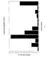
- Figure 10 is a bar chart showing experimental results achieved with a particular shaped conduit 12.
- the same shape conduit 12 was used for all cases but each test involves a different conduit assembly. In each case there is a different collector as compared to test 1 which tests the conduit without a collector or a test of different conduit material.
- the conditions for each test are set out in Figure 11 in table form.
- the horizontal axis of the bar chart of Figure 10 identifies tests 1 through 12.
- the bar chart shows the time in which dripping occurs on the left hand vertical axis.
- the left hand column identifies the tests 1 through 12.
- the second column of Figure 11 identifies the polymer material of the conduit as well as the sleeve material and proportion.
- test number 1 the basic conduit was tested. Dripping occurred in 8 to 12 minutes.
- test number 2 the conduit was equipped with the polypropylene sleeve of the prior art. This improved the time to dripping to between 55 and 90 minutes.
- Test number 3 involved the same conduit with a half encompassing sleeve made of polypropylene but no superabsorbent material fabric. In this case the dripping time was 30 to 40 minutes.
- Test number 4 involves the same conduit but covered with a full covering collector in accordance with this invention. This is a test of the embodiment as shown in Figure 1. In this test, the drip time was between 300 and 360 minutes. The bar chart for test number 4 clearly shows the superiority of this structure over any other structure tested.
- Test number 5 is similar to test number 4 except that a half covering collector in accordance with the invention was used. This is similar to the device as illustrated in Figure 8. With this assembly, the dripping time was from 160 to 180 minutes.
- Test number 6 involves a conduit with a half sleeve of nylon. Dripping time was 60 to 75 minutes.
- Test number 7 involves a conduit manufactured by TPO rather than polypropylene. The test is similar to test number 1. With no collector, the conduit had a dripping time of from 8 to 10 minutes.
- Test number 8 is similar to test number 1 but using a foamed TPO conduit.
- the foamed TPO conduit without a collector has a dripping time of 10 to 11 minutes.
- a low density polyethylene conduit without collector has a dripping time of 20 to 25 minutes as shown in test 9.
- a foam low density polyethylene conduit without collector has a dripping time of 35 to 40 minutes as shown in test number 10.
- a foam polypropylene conduit without collector has a dripping time of 7 to 9 minutes.
- Test number 12 was conducted using a polypropylene conduit covered with a one half covering collector in accordance with this invention and a nylon sleeve. This is a test of the embodiment shown in Figure 9. The dripping time for this type of conduit assembly is about 220 to 240 minutes.
- Test number 12 shows that by reducing the amount of composite material by 50% but adding a nylon sleeve provides a dripping time of 260 minutes as opposed to 360 minutes for the full collector of the type illustrated in Figure 1.
Landscapes
- Engineering & Computer Science (AREA)
- Mechanical Engineering (AREA)
- Manufacturing & Machinery (AREA)
- Physics & Mathematics (AREA)
- Thermal Sciences (AREA)
- Blow-Moulding Or Thermoforming Of Plastics Or The Like (AREA)
- Body Structure For Vehicles (AREA)
- Air-Conditioning For Vehicles (AREA)
Applications Claiming Priority (2)
| Application Number | Priority Date | Filing Date | Title |
|---|---|---|---|
| US09/080,354 US6053215A (en) | 1998-05-18 | 1998-05-18 | Air conditioning duct and method of making |
| US80354 | 1998-05-18 |
Publications (2)
| Publication Number | Publication Date |
|---|---|
| EP0962344A2 true EP0962344A2 (fr) | 1999-12-08 |
| EP0962344A3 EP0962344A3 (fr) | 2002-02-06 |
Family
ID=22156856
Family Applications (1)
| Application Number | Title | Priority Date | Filing Date |
|---|---|---|---|
| EP99303748A Withdrawn EP0962344A3 (fr) | 1998-05-18 | 1999-05-13 | Conduite de climatisation améliorée et son procédé de fabrication |
Country Status (3)
| Country | Link |
|---|---|
| US (1) | US6053215A (fr) |
| EP (1) | EP0962344A3 (fr) |
| CA (1) | CA2270327C (fr) |
Cited By (4)
| Publication number | Priority date | Publication date | Assignee | Title |
|---|---|---|---|---|
| FR2845947A1 (fr) * | 2002-10-18 | 2004-04-23 | Renault Sa | Dispositif de distribution d'air |
| WO2019092183A1 (fr) * | 2017-11-09 | 2019-05-16 | Pervormance International Gmbh | Dispositif de refroidissement pour habitacles de véhicules |
| DE102013202431B4 (de) | 2013-02-14 | 2023-04-27 | Weidmann Plastics Technology Ag | Kraftfahrzeug mit einem Wasserkasten |
| EP4212368A3 (fr) * | 2022-01-18 | 2023-09-13 | WOCO Industrietechnik GmbH | Véhicule automobile et conduit d'air pour guider l'air intérieur dans ou hors d'une cabine d'un véhicule automobile |
Families Citing this family (14)
| Publication number | Priority date | Publication date | Assignee | Title |
|---|---|---|---|---|
| US6929312B2 (en) * | 2003-10-17 | 2005-08-16 | General Motors Corporation | Duct/frame element assemblages and methods of assembling ducts and frame elements |
| US6966829B1 (en) | 2004-05-27 | 2005-11-22 | Lear Corporation | HVAC system for a vehicle with concealed vents |
| US20080233856A1 (en) * | 2007-03-22 | 2008-09-25 | Toyoda Gosei Co., Ltd. | Air conditioner duct |
| USD673668S1 (en) | 2010-02-03 | 2013-01-01 | No-Fade Coatings, Inc. | Ventilator channel |
| WO2012083422A1 (fr) * | 2010-12-02 | 2012-06-28 | Salflex Polymers Limited | Article creux à densité variable de structure de paroi |
| JP6344056B2 (ja) * | 2014-05-23 | 2018-06-20 | キョーラク株式会社 | 発泡成形体 |
| JP6459328B2 (ja) * | 2014-09-16 | 2019-01-30 | 三菱自動車エンジニアリング株式会社 | 車両の空調装置 |
| US9676137B2 (en) * | 2014-10-27 | 2017-06-13 | International Automotive Components Group North America, Inc. | Blow molded airflow conduit with outer insulation |
| JP6369947B2 (ja) * | 2015-11-04 | 2018-08-08 | 株式会社イノアックコーポレーション | ダクト及びダクトの製造方法 |
| JP7457247B2 (ja) * | 2020-04-30 | 2024-03-28 | キョーラク株式会社 | ダクト |
| EP3919299B1 (fr) * | 2020-06-03 | 2025-08-06 | TI Automotive Technology Center GmbH | Agencement tubulaire pour le transport d'un milieu de mise en température |
| JP2023106018A (ja) * | 2022-01-20 | 2023-08-01 | スズキ株式会社 | 車両用空調ダクト |
| CN116252700B (zh) * | 2023-01-09 | 2024-09-06 | 佛山市鼎昊冷链物流有限公司 | 一种冷链物流用冷藏运输设备 |
| USD1112661S1 (en) * | 2024-02-07 | 2026-02-10 | Caterpillar Inc. | Air conditioning duct for construction machine |
Family Cites Families (10)
| Publication number | Priority date | Publication date | Assignee | Title |
|---|---|---|---|---|
| US2089492A (en) * | 1935-07-06 | 1937-08-10 | American Radiator Co | Duct |
| US3823745A (en) * | 1972-11-06 | 1974-07-16 | Keller Glove Mfg Co | Flame-resistant conduit covering |
| JPS6170335A (ja) * | 1984-09-11 | 1986-04-11 | Toyoda Gosei Co Ltd | エアダクト |
| FR2630530B1 (fr) * | 1988-04-22 | 1992-07-17 | Renault | Conduit de ventilation notamment pour la climatisation de vehicules automobiles |
| US5325893A (en) * | 1991-10-04 | 1994-07-05 | Tokushu Paper Mfg. Co., Ltd. | Air duct and paper therefor |
| CA2114454A1 (fr) * | 1994-01-28 | 1995-07-29 | Heinz Bauer | Compresseur |
| JPH08152185A (ja) * | 1994-11-25 | 1996-06-11 | Shin Nippon Kucho Kk | 空調システムにおける結露防止制御方法 |
| JPH0949587A (ja) * | 1995-08-04 | 1997-02-18 | Taiko:Kk | 結露防止可能な保温保冷用被覆層を有するダクトなどの 管構造体 |
| US5705109A (en) * | 1996-06-20 | 1998-01-06 | Westvaco Corporation | Ozone treatment for composite paperboard/polymer package |
| US5906952A (en) * | 1997-03-07 | 1999-05-25 | Nordlys S.A. | Single layer absorbent cable wrap |
-
1998
- 1998-05-18 US US09/080,354 patent/US6053215A/en not_active Expired - Lifetime
-
1999
- 1999-04-28 CA CA002270327A patent/CA2270327C/fr not_active Expired - Fee Related
- 1999-05-13 EP EP99303748A patent/EP0962344A3/fr not_active Withdrawn
Non-Patent Citations (1)
| Title |
|---|
| None |
Cited By (4)
| Publication number | Priority date | Publication date | Assignee | Title |
|---|---|---|---|---|
| FR2845947A1 (fr) * | 2002-10-18 | 2004-04-23 | Renault Sa | Dispositif de distribution d'air |
| DE102013202431B4 (de) | 2013-02-14 | 2023-04-27 | Weidmann Plastics Technology Ag | Kraftfahrzeug mit einem Wasserkasten |
| WO2019092183A1 (fr) * | 2017-11-09 | 2019-05-16 | Pervormance International Gmbh | Dispositif de refroidissement pour habitacles de véhicules |
| EP4212368A3 (fr) * | 2022-01-18 | 2023-09-13 | WOCO Industrietechnik GmbH | Véhicule automobile et conduit d'air pour guider l'air intérieur dans ou hors d'une cabine d'un véhicule automobile |
Also Published As
| Publication number | Publication date |
|---|---|
| EP0962344A3 (fr) | 2002-02-06 |
| US6053215A (en) | 2000-04-25 |
| CA2270327A1 (fr) | 1999-11-18 |
| CA2270327C (fr) | 2004-07-20 |
Similar Documents
| Publication | Publication Date | Title |
|---|---|---|
| US6053215A (en) | Air conditioning duct and method of making | |
| US6524691B2 (en) | Sound absorbing-insulating structure for vehicles | |
| US5841081A (en) | Method of attenuating sound, and acoustical insulation therefor | |
| EP1851092B1 (fr) | Organe pour garniture de pavillon sur des vehicules automobiles de structure multicouche | |
| US20060246799A1 (en) | Sound attenuating/absorbing laminates and methods of making same | |
| US5527581A (en) | Car interior member and molding method of the same | |
| US5997078A (en) | Instrument panel for a motor vehicle | |
| US20030066708A1 (en) | Sound attenuating material for use within vehicles and methods of making same | |
| US20040234685A1 (en) | Porous carpeting for vehicles and methods of producing same | |
| JPH1095060A (ja) | 自動車用車体パネルインシュレータ | |
| JP2005512885A (ja) | スクリム材料を組み入れた騒音減衰複合体およびその製造方法 | |
| KR101432518B1 (ko) | 흡음성능이 우수한 섬유집합체 및 그 제조방법 | |
| KR102420023B1 (ko) | 흡음재 및 이의 제조방법 | |
| JPH08152890A (ja) | 低周波数用吸音材 | |
| EP3531415B1 (fr) | Structure d'insonorisation et procédé de fabrication de structure d'insonorisation | |
| KR102189102B1 (ko) | 흡음재 및 이의 제조방법 | |
| US20060289230A1 (en) | Acoustical insulation for motor vehicles | |
| KR101720162B1 (ko) | 압축회복률 및 흡음특성이 우수한 극세사 흡음재 및 이의 제조방법 및 이를 포함하는 흡음재 | |
| JPH10236238A (ja) | 自動車用内装材 | |
| JP3284729B2 (ja) | 自動車用遮音材及びその製造方法 | |
| KR102415147B1 (ko) | 압축성형체용 숏컷 섬유, 이를 이용한 압축성형체 및 이의 제조방법 | |
| JPH11180224A (ja) | 自動車用内装品および自動車用内装吸音材の配置方法 | |
| EP3078705B1 (fr) | Corps moulé alvéolaire, conduite de climatiseur, et conduite de climatiseur pour véhicule | |
| JP2005104169A (ja) | 空気ダクト | |
| JPH0830274A (ja) | 吸音構造体 |
Legal Events
| Date | Code | Title | Description |
|---|---|---|---|
| PUAI | Public reference made under article 153(3) epc to a published international application that has entered the european phase |
Free format text: ORIGINAL CODE: 0009012 |
|
| AK | Designated contracting states |
Kind code of ref document: A2 Designated state(s): AT BE CH CY DE DK ES FI FR GB GR IE IT LI LU MC NL PT SE Kind code of ref document: A2 Designated state(s): DE ES FR GB IT |
|
| AX | Request for extension of the european patent |
Free format text: AL;LT;LV;MK;RO;SI |
|
| PUAL | Search report despatched |
Free format text: ORIGINAL CODE: 0009013 |
|
| AK | Designated contracting states |
Kind code of ref document: A3 Designated state(s): AT BE CH CY DE DK ES FI FR GB GR IE IT LI LU MC NL PT SE |
|
| AX | Request for extension of the european patent |
Free format text: AL;LT;LV;MK;RO;SI |
|
| 17P | Request for examination filed |
Effective date: 20020613 |
|
| AKX | Designation fees paid |
Free format text: DE ES FR GB IT |
|
| 17Q | First examination report despatched |
Effective date: 20021111 |
|
| STAA | Information on the status of an ep patent application or granted ep patent |
Free format text: STATUS: THE APPLICATION IS DEEMED TO BE WITHDRAWN |
|
| 18D | Application deemed to be withdrawn |
Effective date: 20040603 |