EP0962361A2 - Elektronisches Gerät mit einer erschütterungsempfindlichen Baueinheit - Google Patents
Elektronisches Gerät mit einer erschütterungsempfindlichen Baueinheit Download PDFInfo
- Publication number
- EP0962361A2 EP0962361A2 EP99201661A EP99201661A EP0962361A2 EP 0962361 A2 EP0962361 A2 EP 0962361A2 EP 99201661 A EP99201661 A EP 99201661A EP 99201661 A EP99201661 A EP 99201661A EP 0962361 A2 EP0962361 A2 EP 0962361A2
- Authority
- EP
- European Patent Office
- Prior art keywords
- spring
- vibration
- electronic device
- housing
- sensitive unit
- Prior art date
- Legal status (The legal status is an assumption and is not a legal conclusion. Google has not performed a legal analysis and makes no representation as to the accuracy of the status listed.)
- Granted
Links
- 230000000750 progressive effect Effects 0.000 claims abstract description 27
- 238000013016 damping Methods 0.000 claims abstract description 9
- 238000004804 winding Methods 0.000 claims description 12
- 238000009434 installation Methods 0.000 claims description 4
- 230000003287 optical effect Effects 0.000 claims description 3
- 230000007423 decrease Effects 0.000 claims 1
- 230000005284 excitation Effects 0.000 description 6
- 230000000712 assembly Effects 0.000 description 3
- 238000000429 assembly Methods 0.000 description 3
- 230000035939 shock Effects 0.000 description 2
- 230000010355 oscillation Effects 0.000 description 1
Images
Classifications
-
- F—MECHANICAL ENGINEERING; LIGHTING; HEATING; WEAPONS; BLASTING
- F16—ENGINEERING ELEMENTS AND UNITS; GENERAL MEASURES FOR PRODUCING AND MAINTAINING EFFECTIVE FUNCTIONING OF MACHINES OR INSTALLATIONS; THERMAL INSULATION IN GENERAL
- F16F—SPRINGS; SHOCK-ABSORBERS; MEANS FOR DAMPING VIBRATION
- F16F15/00—Suppression of vibrations in systems; Means or arrangements for avoiding or reducing out-of-balance forces, e.g. due to motion
- F16F15/02—Suppression of vibrations of non-rotating, e.g. reciprocating systems; Suppression of vibrations of rotating systems by use of members not moving with the rotating systems
- F16F15/04—Suppression of vibrations of non-rotating, e.g. reciprocating systems; Suppression of vibrations of rotating systems by use of members not moving with the rotating systems using elastic means
- F16F15/06—Suppression of vibrations of non-rotating, e.g. reciprocating systems; Suppression of vibrations of rotating systems by use of members not moving with the rotating systems using elastic means with metal springs
- F16F15/067—Suppression of vibrations of non-rotating, e.g. reciprocating systems; Suppression of vibrations of rotating systems by use of members not moving with the rotating systems using elastic means with metal springs using only wound springs
-
- F—MECHANICAL ENGINEERING; LIGHTING; HEATING; WEAPONS; BLASTING
- F16—ENGINEERING ELEMENTS AND UNITS; GENERAL MEASURES FOR PRODUCING AND MAINTAINING EFFECTIVE FUNCTIONING OF MACHINES OR INSTALLATIONS; THERMAL INSULATION IN GENERAL
- F16F—SPRINGS; SHOCK-ABSORBERS; MEANS FOR DAMPING VIBRATION
- F16F15/00—Suppression of vibrations in systems; Means or arrangements for avoiding or reducing out-of-balance forces, e.g. due to motion
- F16F15/02—Suppression of vibrations of non-rotating, e.g. reciprocating systems; Suppression of vibrations of rotating systems by use of members not moving with the rotating systems
- F16F15/04—Suppression of vibrations of non-rotating, e.g. reciprocating systems; Suppression of vibrations of rotating systems by use of members not moving with the rotating systems using elastic means
- F16F15/08—Suppression of vibrations of non-rotating, e.g. reciprocating systems; Suppression of vibrations of rotating systems by use of members not moving with the rotating systems using elastic means with rubber springs ; with springs made of rubber and metal
- F16F15/085—Use of both rubber and metal springs
-
- F—MECHANICAL ENGINEERING; LIGHTING; HEATING; WEAPONS; BLASTING
- F16—ENGINEERING ELEMENTS AND UNITS; GENERAL MEASURES FOR PRODUCING AND MAINTAINING EFFECTIVE FUNCTIONING OF MACHINES OR INSTALLATIONS; THERMAL INSULATION IN GENERAL
- F16F—SPRINGS; SHOCK-ABSORBERS; MEANS FOR DAMPING VIBRATION
- F16F3/00—Spring units consisting of several springs, e.g. for obtaining a desired spring characteristic
- F16F3/08—Spring units consisting of several springs, e.g. for obtaining a desired spring characteristic with springs made of a material having high internal friction, e.g. rubber
- F16F3/10—Spring units consisting of several springs, e.g. for obtaining a desired spring characteristic with springs made of a material having high internal friction, e.g. rubber combined with springs made of steel or other material having low internal friction
- F16F3/12—Spring units consisting of several springs, e.g. for obtaining a desired spring characteristic with springs made of a material having high internal friction, e.g. rubber combined with springs made of steel or other material having low internal friction the steel spring being in contact with the rubber spring
-
- H—ELECTRICITY
- H05—ELECTRIC TECHNIQUES NOT OTHERWISE PROVIDED FOR
- H05K—PRINTED CIRCUITS; CASINGS OR CONSTRUCTIONAL DETAILS OF ELECTRIC APPARATUS; MANUFACTURE OF ASSEMBLAGES OF ELECTRICAL COMPONENTS
- H05K7/00—Constructional details common to different types of electric apparatus
- H05K7/14—Mounting supporting structure in casing or on frame or rack
Definitions
- the invention relates to an electronic device with a vibration-sensitive Unit, which is arranged in a housing, the housing and the vibration-sensitive unit is coupled by means of damping means.
- Such an electronic device is known for example from DE 39 14 303 A1.
- coil springs provided with a linear spring force characteristic.
- the Vibration amplitude of such coil springs is with low-frequency vibration excitation larger than with high-frequency vibration excitation.
- the vibration space of the Vibration sensitive unit must therefore in such devices with regard to lowest excitation frequencies occurring during operation.
- a progressive spring characteristic is understood to mean that the spring force increases with Vibration amplitude progressive, i.e. disproportionately, increases.
- the spring characteristic which is progressive in three spatial directions, is used in all three A progressive damping of vibrations that occur.
- the three spatial directions are spatial directions of a Cartesian coordinate system Understood. There is an axis of this Cartesian coordinate system preferably arranged in the direction of the longitudinal axis of the spring arrangement.
- the Vibrations that occur are damped progressively in three dimensions.
- the vibration amplitude of the low frequency vibrations is determined by the non-linear Adjustment of the spring with a progressive spring characteristic reduced. This will the necessary vibration space of the vibration-sensitive assembly in all three spatial directions and thus the installation space of the electronic device in all three Reduced spatial directions.
- the spring arrangement a coil spring with a non-linear pitch.
- This non-linear Winding distance causes a non-linear, progressive spring characteristic of the coil spring in the axial direction of the coil spring.
- Inside the coil spring is a Spring core arranged, the radial distance between the turns of the coil spring and the spring core is not constant. This means that with increasing Vibration amplitude an ever larger proportion of the turns of the coil spring comes to rest on the spring core, whereby the vibrations with increasing Vibration amplitude can be damped progressively and in the radial direction of the coil spring extending spatial directions results in a progressive spring characteristic.
- the spring core is fixed connected to the housing.
- the radial distance between the turns of the coil spring and the spring core takes from the housing towards the vibration sensitive Unit, i.e. near the case is the distance between the turns of the coil spring and the innerspring relatively small, while it is relatively large in the vicinity of the vibration-sensitive assembly.
- the vibration-sensitive unit therefore comes with increasing Vibration amplitude of the coil spring first on the near the Housing part of the spring core to the system.
- With increasing vibration amplitude then an ever larger proportion of the turns of the coil spring arrive the spring core to the system, which extends in the radially to the coil spring A progressive spring characteristic and thus a progressive one Damping the vibration amplitude results.
- the spring core with the vibration-sensitive Unit connected and therefore vibrates with the vibration sensitive Unit with.
- the radial distance between the turns of the coil spring and the spring core in this embodiment takes in from the housing Direction towards the vibration-sensitive unit, i.e. near the vibration sensitive
- the unit is the distance between the turns of the Coil spring and the spring core relatively small while close to the case is relatively large. If vibrations occur in the vibration-sensitive unit therefore only the turns come with increasing vibration amplitude the coil spring with the spring core to the system, which is close to the vibration-sensitive Unit. With increasing vibration amplitude an increasing proportion of the coils of the coil spring then come along the spring core to the system, which results in a progressive spring characteristic in the radial direction and thus a progressive damping of the vibration amplitudes of the vibration-sensitive Unit result.
- the configurations of the electronic device according to the invention can preferably be in devices for playing or writing to optical storage disks, such as for example, use CDs or DVDs.
- the electronic according to the invention Device suitable for installation in vehicles, as available in vehicles standing space is limited and a lot during the journey vibrations of different frequencies occur.
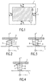
- Fig. 1 shows a schematic top view of an electronic device which has a housing 1, in which a vibration-sensitive unit 2 is arranged.
- the vibration sensitive Unit 2 is with the housing 1 by means of four spring arrangements 3 coupled.
- the spring arrangements 3 each have a cylindrical helical spring 4 on.
- the cylindrical coil springs 4 have a non-linear winding spacing on, which extends in the direction of the longitudinal axis of the cylindrical coil springs 4 results in a progressive spring characteristic.
- the cylindrical coil springs 4 are on the one hand on the housing 1 and on the other hand on the vibration-sensitive Unit 2 attached.
- Within each of the cylindrical coil springs 4 is a conical spring core 5 arranged.
- the conical spring core 5 is fixed to the housing 1 connected.
- the end of the conical spring cores 5 is slightly spaced from the vibration-sensitive Unit 2 arranged so that for the vibration sensitive Unit 2, a vibration space S is available.
- the spring assemblies 3 serve to decouple external vibrations and / or shocks between the housing 1 and the vibration-sensitive unit 2.
- Fig. 2 shows an enlarged view of the between FIG. 1 between the housing 1 and vibration-sensitive assembly 2 arranged spring assemblies 3.
- the distance between the individual turns of the cylindrical coil spring 4 nonlinear.
- the distance between the turns in a central region is Coil spring 4 larger than in the edge areas of the coil spring 4. This will achieved a progressive spring characteristic in the direction of the longitudinal axis Z of the coil spring 4.
- the spring core 5 is tapered and tapers from the housing 1 in the direction of the vibration-sensitive assembly 2. This ensures that the radial distance d in the radial direction r between the individual turns of the Coil spring 4 and the spring core 5 from the housing 1 in the direction of the vibration-sensitive Unit 2 increases.
- the oscillation amplitude increases Windings of the helical spring 4 first in the vicinity of the housing 1 on the conical Innerspring 5. With increasing vibration amplitude comes an ever larger part the turns of the coil spring 4 on the spring core 5 to the system. This ensures that the vibrations with increasing vibration amplitude by means of the spring arrangements 3 be damped progressively and thus also in the radial direction r results in a progressive spring characteristic. Overall, the spring assemblies 3 thus have a progressive spring characteristic in all three spatial directions.
- the vibration amplitudes of coil springs are with low-frequency vibration excitation larger than with high-frequency vibration excitation.
- the necessary vibration space 5 must therefore with regard to the lowest excitation frequencies occurring during operation be interpreted.
- the electronic device shown in FIG. 1 is preferred a CD or DVD device intended for use in a vehicle is.
- the space available for such a device is in a vehicle naturally limited.
- the progressive spring characteristic of the spring arrangements 3 the vibration amplitude for the lowest vibration frequency determining the installation space lowered, so that the vibration space 5 and thus the overall space for the housing 1 can be reduced compared to arrangements with linear spring characteristics can.
- FIG. 3 shows an alternative spring arrangement 6 with a cylindrical coil spring 7.
- This spring arrangement 6 can also be used for decoupling between the housing 1 and the vibration-sensitive unit 2 shown in FIG. 1 can be used.
- the cylindrical spring 7 is between the vibration-sensitive unit 2 and the Housing 1 firmly clamped.
- Inside the cylindrical coil spring 7 is a conical one Spring core 8 arranged, but in contrast to the arrangement according to FIG. 2 not is attached to the housing 1, but to the vibration-sensitive unit 2.
- the conical spring core 8 thus swings with the vibration-sensitive unit 2 with.
- the spring core 8 tapers conically from the vibration-sensitive Assembly 2 in the direction of the housing 1.
- the progressive spring characteristic is in the z-direction 2 achieved in that the winding distance between the individual turns of the coil spring 7 in the central region of the coil spring 7 is greater than in the edge regions of the coil spring 7. This results overall also for the spring arrangement according to FIG. 3 a progressive in all three spatial directions Spring characteristic.
- FIG. 4 Another alternative spring arrangement 11 for decoupling between the housing 1 and the vibration-sensitive assembly 2 according to FIG. 1 is in FIG. 4 shown schematically.
- a conical coil spring 9 Between the housing 1 and the vibration sensitive Unit 2 is arranged a conical coil spring 9 and on the one hand on the vibration-sensitive Unit 2 and on the other hand attached to the housing 1.
- the Winding distance of the conical coil spring 9 is non-linear in the z-direction, which is achieved in that the winding spacing in the central region of the conical Coil spring 9 is larger than in the edge regions of the conical coil spring 9.
- the radial diameter in the radial direction r of the conical coil spring 9 tapers towards the housing 1, i.e. he is close to the vibration sensitive Unit 2 larger than near the housing 1.
- a conical spring core 10 is arranged on the Housing 1 is attached.
- the conical spring core 10 tapers in the direction of the Housing 1.
- the degree of tapering of the conical spring core 10 is designed such that the radial distance d between the turns of the coil spring 9 and the spring core 10 increases from the housing 1 towards the vibration-sensitive assembly 2. This results in a progressive characteristic of the spring arrangement according to FIG radial direction r achieved. Overall, there is a progressive spring characteristic in all three spatial directions.
Landscapes
- Engineering & Computer Science (AREA)
- General Engineering & Computer Science (AREA)
- Mechanical Engineering (AREA)
- Physics & Mathematics (AREA)
- Acoustics & Sound (AREA)
- Aviation & Aerospace Engineering (AREA)
- Chemical & Material Sciences (AREA)
- Combustion & Propulsion (AREA)
- Microelectronics & Electronic Packaging (AREA)
- Vibration Prevention Devices (AREA)
- Springs (AREA)
- Apparatuses For Generation Of Mechanical Vibrations (AREA)
Abstract
Description
Claims (9)
- Elektronisches Gerät mit einer erschütterungsempfindlichen Baueinheit (2), die in einem Gehäuse (1) angeordnet ist, wobei das Gehäuse (1) und die erschütterungsempfindliche Baueinheit (2) mittels Dämpfungsmitteln (3, 6, 11) gekoppelt sind,
dadurch gekennzeichnet, daß als Dämpfungsmittel wenigstens eine Federanordnung (3, 6, 11) vorgesehen die eine progressive Federkennlinie aufweist, insbesondere eine in drei Raumrichtungen progressive Federkennlinie. - Elektronisches Gerät nach Anspruch 1,
dadurch gekennzeichnet, daß die Federanordnung (3, 6, 11) eine Schraubenfeder (4, 7, 9) mit nichtlinearem Windungsabstand aufweist, und daß innerhalb der Schraubenfeder (4, 7, 9) ein Federkern (5, 8, 10) angeordnet ist, wobei die Schraubenfeder (4, 7, 9) und der Federkern (5, 8, 10) so ausgebildet sind, daß der radiale Abstand zwischen den Windungen der Schraubenfeder (4, 7, 9) und dem Federkern (5, 8, 10) nicht konstant ist. - Elektronisches Gerät nach Anspruch 2,
dadurch gekennzeichnet, daß der Federkern (5, 10) an dem Gehäuse (1) befestigt ist und daß der radiale Abstand (d) zwischen den Windungen der Schraubenfeder (4, 9) und dem Federkern (5, 10) von dem Gehäuse (1) in Richtung auf die erschütterungsempfindlichen Baueinheit (2) zunimmt. - Elektronisches Gerät nach Anspruch 2,
dadurch gekennzeichnet, daß der Federkern (8) an der erschütterungsempfindlichen Baueinheit (2) befestigt ist und daß der radiale Abstand (d) zwischen den Windungen der Schraubenfeder (7) und dem Federkern (8) von dem Gehäuse (1) in Richtung auf die erschütterungsempfindliche Baueinheit (2) abnimmt. - Elektronisches Gerät nach einem der Ansprüche 1 bis 4,
dadurch gekennzeichnet, daß die Feder eine kegelförmige Schraubenfeder mit nichtlinearem Windungsabstand ist. - Elektronisches Gerät nach einem der Ansprüche 1 bis 4,
dadurch gekennzeichnet, daß die Feder eine zylinderförmige Schraubenfeder (4, 7) mit nichtlinearem Windungsabstand ist. - Elektronisches Gerät nach einem der Ansprüche 1 bis 6,
dadurch gekennzeichnet, daß das Gerät ein Gerät zum Lesen von auf einer optischen Speicherplatte gespeicherten Informationen und/oder zum Schreiben von Informationen auf eine optische Speicherplatte, insbesondere ein CD/DVD-Gerät, ist. - Elektronisches Gerät nach einem der Ansprüche 1 bis 7,
dadurch gekennzeichnet, daß das elektronische Gerät zum Einbau in ein Fahrzeug vorgesehen ist. - Fahrzeug mit einem elektronischen Gerät nach einem der Ansprüche 1 bis 8.
Applications Claiming Priority (2)
| Application Number | Priority Date | Filing Date | Title |
|---|---|---|---|
| DE19824378 | 1998-05-30 | ||
| DE19824378A DE19824378A1 (de) | 1998-05-30 | 1998-05-30 | Elektonisches Gerät mit einer erschütterungsempfindliches Baueinheit |
Publications (3)
| Publication Number | Publication Date |
|---|---|
| EP0962361A2 true EP0962361A2 (de) | 1999-12-08 |
| EP0962361A3 EP0962361A3 (de) | 2003-10-22 |
| EP0962361B1 EP0962361B1 (de) | 2006-04-05 |
Family
ID=7869502
Family Applications (1)
| Application Number | Title | Priority Date | Filing Date |
|---|---|---|---|
| EP99201661A Expired - Lifetime EP0962361B1 (de) | 1998-05-30 | 1999-05-26 | Elektronisches Gerät mit einer erschütterungsempfindlichen Baueinheit |
Country Status (6)
| Country | Link |
|---|---|
| US (1) | US6402219B1 (de) |
| EP (1) | EP0962361B1 (de) |
| JP (1) | JP2000027943A (de) |
| CN (1) | CN1125931C (de) |
| DE (2) | DE19824378A1 (de) |
| SG (1) | SG71929A1 (de) |
Cited By (1)
| Publication number | Priority date | Publication date | Assignee | Title |
|---|---|---|---|---|
| DE10041206A1 (de) * | 2000-08-22 | 2002-03-07 | Continental Teves Ag & Co Ohg | Bremsaggregat |
Families Citing this family (21)
| Publication number | Priority date | Publication date | Assignee | Title |
|---|---|---|---|---|
| US6683745B1 (en) * | 1999-12-27 | 2004-01-27 | Hitachi Global Storage Technologies Netherlands B.V. | Rotationally free mount system for disk drive having a rotary actuator |
| US20040108991A1 (en) * | 2002-12-04 | 2004-06-10 | Steven Chang | Cushion for an overhead LCD monitor in combination with a DVD player in an automobile |
| JP2005104425A (ja) * | 2003-10-02 | 2005-04-21 | T S Tec Kk | 車両用シート |
| US8235351B1 (en) * | 2009-08-27 | 2012-08-07 | Lockheed Martin Corporation | Shock load isolation mounting |
| EP2600348A4 (de) * | 2010-07-30 | 2018-01-24 | Tokkyokiki Corporation | Audioisolator und verfahren zu seiner bewertung |
| CN102032926A (zh) * | 2010-12-01 | 2011-04-27 | 南京物联传感技术有限公司 | 一种振动/震动记录仪的信号处理模块安装结构 |
| US9249984B2 (en) | 2012-08-16 | 2016-02-02 | Carrier Corporation | Base pan |
| CN104455194A (zh) * | 2014-12-03 | 2015-03-25 | 成都艾塔科技有限公司 | 一种多媒体投影仪的减震机构 |
| CN104532976B (zh) * | 2014-12-11 | 2016-10-05 | 中国十七冶集团有限公司 | 建筑用粘弹性阻尼万向铰支座及其使用方法 |
| CN104455195B (zh) * | 2014-12-16 | 2016-06-15 | 中国电子科技集团公司第十研究所 | 全金属多向隔振器 |
| CN104847831B (zh) * | 2015-05-05 | 2017-01-11 | 常州大学 | 基于电动阻尼解耦的三向等刚度隔振器 |
| CN104832592B (zh) * | 2015-05-05 | 2017-01-11 | 常州大学 | 基于气浮阻尼三向解耦的自适应等刚度隔振器 |
| CN107996033A (zh) * | 2015-06-26 | 2018-05-04 | 博世汽车多媒体葡萄牙公司 | 用于印刷电路板的固定和接地触头的弹簧 |
| US10107378B2 (en) * | 2015-11-03 | 2018-10-23 | General Electric Company | Systems and methods for a gas turbine engine with combined multi-directional gearbox deflection limiters and dampers |
| CN105263279A (zh) * | 2015-11-24 | 2016-01-20 | 南京苏铁经济技术发展有限公司 | 一种抗冲击轨道交通用电气控制柜 |
| CN107600006A (zh) * | 2017-08-31 | 2018-01-19 | 苏州惠华电子科技有限公司 | 一种防止振动破裂的汽车线束保护管固定装置 |
| CN108167365B (zh) * | 2018-02-09 | 2024-06-25 | 中国工程物理研究院总体工程研究所 | 一种压紧力可调的径向压紧减振装置 |
| CN111196436A (zh) * | 2019-12-31 | 2020-05-26 | 国望智承(北京)振动控制技术有限公司 | 一种高效率运输防振包装箱结构 |
| CN113422490B (zh) * | 2021-07-19 | 2023-01-03 | 深圳市信为科技发展有限公司 | 一种宽频振动能量搜集装置 |
| JP2025519470A (ja) * | 2022-06-07 | 2025-06-26 | メタセイズミック インク. | 衝撃と振動から保護する3つの適応装置 |
| CN116733879A (zh) * | 2023-06-25 | 2023-09-12 | 中国长江三峡集团有限公司 | 一种风力发电机塔架阻尼器及全角度减振方法 |
Citations (1)
| Publication number | Priority date | Publication date | Assignee | Title |
|---|---|---|---|---|
| DE3914303A1 (de) | 1989-04-29 | 1990-10-31 | Thomson Brandt Gmbh | Erschuetterungsempfindliches geraet |
Family Cites Families (47)
| Publication number | Priority date | Publication date | Assignee | Title |
|---|---|---|---|---|
| US2270335A (en) * | 1939-12-30 | 1942-01-20 | Johns Manville | Vibration isolator |
| US2605099A (en) * | 1949-01-07 | 1952-07-29 | Firestone Tire & Rubber Co | Rubber-metal spring |
| US3263953A (en) * | 1963-04-30 | 1966-08-02 | Pilot Radio Inc | Vibration isolation mount |
| AT293112B (de) * | 1968-06-18 | 1971-09-27 | Steirische Gussstahlwerke | Reibungsfeder |
| US3531069A (en) * | 1968-11-27 | 1970-09-29 | Gen Electric | Vibration mount for compressors and the like |
| DE2020678A1 (de) * | 1970-04-28 | 1971-11-25 | Daimler Benz Ag | Schrauben-Druckfeder |
| US4120489A (en) * | 1970-06-22 | 1978-10-17 | Bebrueder Ahle | Double truncoconical spring of wire with circular cross section |
| DE2122118A1 (de) * | 1971-05-05 | 1972-11-16 | Freyler, Adalbert, 5600 Wuppertal-Elberfeld | Stoss- und Schwingungsdämpfer in Teleskopform, insbesondere für Kraftfahrzeuge |
| US3895586A (en) * | 1974-06-17 | 1975-07-22 | Elwood H Willetts | Railraod car supsension system |
| DE2506420C3 (de) * | 1975-02-15 | 1982-03-11 | Gebrüder Ahle, 5253 Lindlar | Nichtzylindrische, gewundene Druckfeder aus Draht mit kreisförmigem Querschnitt, insbesondere zur Anwendung bei Kraftfahrzeugen |
| DE2641656C3 (de) * | 1976-09-16 | 1981-06-11 | Waggonfabrik Uerdingen AG, Werk Düsseldorf, 4000 Düsseldorf | Radsatzlagerfederung |
| US4111407A (en) * | 1976-09-30 | 1978-09-05 | Litton Industrial Products, Inc. | Conical compression spring |
| FR2375077A1 (fr) * | 1976-12-23 | 1978-07-21 | Wabco Westinghouse Gmbh | Regulateur de la force de freinage en fonction de la charge |
| AT350337B (de) * | 1977-06-17 | 1979-05-25 | Sticht Walter | Stossdaempferanordnung, insbesondere fuer montagemaschinen |
| DE2918763C2 (de) * | 1979-05-09 | 1986-09-11 | Kraftwerk Union AG, 4330 Mülheim | Lageranordnung für Läufer elektrischer Maschinen, insbesondere für den Läufer eines Turbogenerators mit supraleitender Feldwicklung |
| FR2531561B3 (fr) * | 1982-08-09 | 1985-07-26 | Bernard Georges | Platine de lecture de disque |
| EP0128971A1 (de) * | 1983-06-21 | 1984-12-27 | International Business Machines Corporation | Vibrationsfilter |
| DE3537573A1 (de) * | 1984-10-25 | 1986-04-30 | Mitsubishi Denki K.K., Tokio/Tokyo | Akustisches geraet |
| USRE33696E (en) * | 1984-12-12 | 1991-09-24 | The Paton Corporation | Composite spring |
| DE3514164A1 (de) * | 1985-04-19 | 1986-10-23 | Deutsche Thomson-Brandt Gmbh, 7730 Villingen-Schwenningen | Elastische lagerung mit einstellbarer daempfung fuer schallplattenspieler |
| DE8522888U1 (de) * | 1985-08-08 | 1985-10-10 | Fichtel & Sachs Ag, 8720 Schweinfurt | Progressive Druckfeder in Kupplungsscheiben |
| CH672009A5 (de) * | 1986-10-24 | 1989-10-13 | Schrepfer Rudolf Ag | |
| DE3703483A1 (de) * | 1987-02-05 | 1988-08-18 | Messerschmitt Boelkow Blohm | Schwingungsisolator |
| JPS63261593A (ja) * | 1987-04-20 | 1988-10-28 | Hitachi Ltd | ユニツトメカの防振ゴム |
| NL8700969A (nl) * | 1987-04-24 | 1988-11-16 | Philips Nv | Inrichting voor het steunen van een subgestel van een platenspeler op een gestel, alsmede platenspeler voorzien van een dergelijke inrichting. |
| US4957277A (en) * | 1987-06-15 | 1990-09-18 | Paton H N | Tubular elastomeric spring having controllable breakover and spring rate |
| DE3737104A1 (de) * | 1987-11-02 | 1989-05-11 | Altenkirchener Kunststoff | Schlauchstueck aus elastischem, gut rueckstellbarem kunststoff und verfahren zu seiner herstellung |
| US4846382A (en) * | 1988-01-13 | 1989-07-11 | Nancy E. Foultner | Dash mounting device |
| AT389791B (de) * | 1988-04-13 | 1990-01-25 | Akg Akustische Kino Geraete | Federnd befestigte halteeinrichtung fuer ein mikrophon |
| US5042024A (en) * | 1989-04-28 | 1991-08-20 | Pioneer Electronic Corporation | Disk reproduction apparatus capable of being disposed in different attitudes |
| US5347507A (en) * | 1989-04-29 | 1994-09-13 | Deutsche Thomson-Brandt Gmbh | Apparatus with adjustable isolation resilience consumer electronics |
| DE3915311A1 (de) * | 1989-05-10 | 1990-11-22 | Metzeler Gmbh | Hydraulisch wirkendes daempfungselement |
| US5088571A (en) * | 1990-12-17 | 1992-02-18 | General Motors Corporation | Modular structural instrument panel carrier |
| US5102181A (en) * | 1991-05-31 | 1992-04-07 | Pinkney Osten C | Concealed rotating radio for car dashboards and the like |
| US5282556A (en) * | 1991-09-30 | 1994-02-01 | Organizer's, Inc. | Vehicle organizing container |
| DE4138961A1 (de) * | 1991-11-27 | 1993-06-03 | Ymos Ag Ind Produkte | Maschinenfuss |
| DE9201144U1 (de) * | 1992-01-31 | 1993-06-03 | Robert Bosch Gmbh, 7000 Stuttgart | Einrichtung zur schwingungsdämpfenden Lagerung einer Trägerplatte auf einem Gehäuseteil |
| JPH06119770A (ja) * | 1992-08-18 | 1994-04-28 | Sony Corp | 防振機構 |
| MY112103A (en) * | 1993-08-26 | 2001-04-30 | Sony Corp | Recording and / or reproducing apparatus for recording medium and damper mechanism employed in such apparatus. |
| US5386962A (en) * | 1993-11-15 | 1995-02-07 | Puritan Bennett Corporation | Shock and vibration absorbing mounts |
| US5425531A (en) * | 1994-08-24 | 1995-06-20 | Perrault; George G. | Inner and outer conical spring sections with axially movable plug |
| JPH08210438A (ja) * | 1995-02-01 | 1996-08-20 | Nippon Steel Corp | 振動抑制装置 |
| DE19608793B4 (de) * | 1996-03-07 | 2005-12-29 | Fa. Andreas Stihl | Schwingungsdämpfende Lageranordnung für den Antriebsmotor eines rückentragbaren Freischneidegerätes |
| KR970064007U (ko) * | 1996-05-28 | 1997-12-11 | 카 오디오의 탈거 구조 | |
| US5875567A (en) * | 1997-04-21 | 1999-03-02 | Bayley; Richard | Shoe with composite spring heel |
| US5878998A (en) * | 1997-08-27 | 1999-03-09 | Hsieh; Frank | Conical spring |
| JPH11159551A (ja) * | 1997-11-27 | 1999-06-15 | Tama Spring:Kk | 非線形異形コイルばね |
-
1998
- 1998-05-30 DE DE19824378A patent/DE19824378A1/de not_active Withdrawn
-
1999
- 1999-05-26 DE DE59913292T patent/DE59913292D1/de not_active Expired - Fee Related
- 1999-05-26 EP EP99201661A patent/EP0962361B1/de not_active Expired - Lifetime
- 1999-05-27 US US09/320,815 patent/US6402219B1/en not_active Expired - Fee Related
- 1999-05-27 CN CN99109794A patent/CN1125931C/zh not_active Expired - Fee Related
- 1999-05-27 SG SG1999002899A patent/SG71929A1/en unknown
- 1999-05-31 JP JP11151225A patent/JP2000027943A/ja active Pending
Patent Citations (1)
| Publication number | Priority date | Publication date | Assignee | Title |
|---|---|---|---|---|
| DE3914303A1 (de) | 1989-04-29 | 1990-10-31 | Thomson Brandt Gmbh | Erschuetterungsempfindliches geraet |
Cited By (1)
| Publication number | Priority date | Publication date | Assignee | Title |
|---|---|---|---|---|
| DE10041206A1 (de) * | 2000-08-22 | 2002-03-07 | Continental Teves Ag & Co Ohg | Bremsaggregat |
Also Published As
| Publication number | Publication date |
|---|---|
| CN1125931C (zh) | 2003-10-29 |
| JP2000027943A (ja) | 2000-01-25 |
| DE59913292D1 (de) | 2006-05-18 |
| EP0962361B1 (de) | 2006-04-05 |
| CN1246584A (zh) | 2000-03-08 |
| US6402219B1 (en) | 2002-06-11 |
| SG71929A1 (en) | 2000-04-18 |
| EP0962361A3 (de) | 2003-10-22 |
| DE19824378A1 (de) | 1999-12-02 |
Similar Documents
| Publication | Publication Date | Title |
|---|---|---|
| EP0962361B1 (de) | Elektronisches Gerät mit einer erschütterungsempfindlichen Baueinheit | |
| DE69623736T2 (de) | Drehendes Gerät zur Datenaufnahme und -wiedergabe | |
| DE69729844T2 (de) | Anisotroper Dämpfer | |
| DE69313516T2 (de) | Plattenklemmvorrichtung mit niedrigem Profil | |
| EP0923684A2 (de) | Federanordnung zur lagerung eines an einem trägerteil befestigten vibrations- oder stossempfindlichen gerätes in einem gehäuse | |
| DE69807588T2 (de) | Plattenaufnahme- und -wiedergabegerät und Schwingungsdämpfer hierzu | |
| DE102010060935A1 (de) | Aktive dynamische Vibrationsabsorptionsvorrichtung für ein Fahrzeug | |
| EP0543083A1 (de) | Schwingungsdämpfer | |
| DE102017112167A1 (de) | Vibrations-Grenzstandsensor mit optimiertem induktivem Antrieb | |
| EP0553633A1 (de) | Einrichtung zur schwingungsdämpfenden Lagerung einer Trägerplatte auf einem Gehäuseteil | |
| EP0221097B1 (de) | Elastische lagerung mit einstellbarer dämpfung für schallplattenspieler | |
| DE102006049066A1 (de) | HF-Abschirmverfahren, MR-Bildgebungsvorrichtung und Sende/Empfangs-Oberflächenspule | |
| EP0424482B1 (de) | Gerät mit erschütterungsempfindlichen teilen | |
| EP1371996A2 (de) | Vorrichtung zur Positionierung eines länglichen Probenröhrchens relativ zu einem NMR-Empfangsspulensystem | |
| DE102010016678A1 (de) | Festplattenlaufwerk | |
| DE69827854T2 (de) | Trägerstruktur eines schwimmend gelagertem Chassis für ein Plattengerät | |
| DE2614853B2 (de) | ||
| DE102018120926A1 (de) | Head-up-Display für ein Kraftfahrzeug mit Dämpfungselement zwischen einer Deckeleinrichtung und einer Gehäuseeinrichtung sowie Verfahren | |
| DE69715834T2 (de) | Dämpfende anordnung zur befestigung einer vorrichtung zum schutz gegen mindestens einige schwingungen | |
| DE60205178T2 (de) | Schwingungsdämpfender Mechanismus | |
| EP1117485A1 (de) | Unwuchtsaugleichsvorrichtung für zentrifugen | |
| EP0574069A2 (de) | Gerät zum Abtasten eines Kreisscheibenförmigen Aufzeichnungsträgers | |
| DE102010050289B4 (de) | Dämpferlager zur Abstützung einer Fahrwerkskomponente an einer Kraftfahrzeugkarosserie | |
| DE19838753A1 (de) | Flüssigkeitsgefüllter Dämpfer für ein erschütterungsempfindliches Gerät und Verfahren zu dessen Herstellung | |
| EP1068614B1 (de) | Abspielgerät |
Legal Events
| Date | Code | Title | Description |
|---|---|---|---|
| PUAI | Public reference made under article 153(3) epc to a published international application that has entered the european phase |
Free format text: ORIGINAL CODE: 0009012 |
|
| AK | Designated contracting states |
Kind code of ref document: A2 Designated state(s): AT BE CH CY DE DK ES FI FR GB GR IE IT LI LU MC NL PT SE |
|
| AX | Request for extension of the european patent |
Free format text: AL;LT;LV;MK;RO;SI |
|
| RAP3 | Party data changed (applicant data changed or rights of an application transferred) |
Owner name: KONINKLIJKE PHILIPS ELECTRONICS N.V. Owner name: PHILIPS CORPORATE INTELLECTUAL PROPERTY GMBH |
|
| RAP1 | Party data changed (applicant data changed or rights of an application transferred) |
Owner name: KONINKLIJKE PHILIPS ELECTRONICS N.V. Owner name: PHILIPS CORPORATE INTELLECTUAL PROPERTY GMBH |
|
| RAP1 | Party data changed (applicant data changed or rights of an application transferred) |
Owner name: KONINKLIJKE PHILIPS ELECTRONICS N.V. Owner name: PHILIPS INTELLECTUAL PROPERTY & STANDARDS GMBH |
|
| PUAL | Search report despatched |
Free format text: ORIGINAL CODE: 0009013 |
|
| AK | Designated contracting states |
Kind code of ref document: A3 Designated state(s): AT BE CH CY DE DK ES FI FR GB GR IE IT LI LU MC NL PT SE |
|
| AX | Request for extension of the european patent |
Extension state: AL LT LV MK RO SI |
|
| 17P | Request for examination filed |
Effective date: 20040422 |
|
| AKX | Designation fees paid |
Designated state(s): DE FR GB IT |
|
| 17Q | First examination report despatched |
Effective date: 20050422 |
|
| GRAP | Despatch of communication of intention to grant a patent |
Free format text: ORIGINAL CODE: EPIDOSNIGR1 |
|
| GRAS | Grant fee paid |
Free format text: ORIGINAL CODE: EPIDOSNIGR3 |
|
| GRAA | (expected) grant |
Free format text: ORIGINAL CODE: 0009210 |
|
| AK | Designated contracting states |
Kind code of ref document: B1 Designated state(s): DE FR GB IT |
|
| REG | Reference to a national code |
Ref country code: GB Ref legal event code: FG4D Free format text: NOT ENGLISH |
|
| REF | Corresponds to: |
Ref document number: 59913292 Country of ref document: DE Date of ref document: 20060518 Kind code of ref document: P |
|
| GBT | Gb: translation of ep patent filed (gb section 77(6)(a)/1977) |
Effective date: 20060524 |
|
| ET | Fr: translation filed | ||
| PLBE | No opposition filed within time limit |
Free format text: ORIGINAL CODE: 0009261 |
|
| STAA | Information on the status of an ep patent application or granted ep patent |
Free format text: STATUS: NO OPPOSITION FILED WITHIN TIME LIMIT |
|
| 26N | No opposition filed |
Effective date: 20070108 |
|
| PGFP | Annual fee paid to national office [announced via postgrant information from national office to epo] |
Ref country code: DE Payment date: 20070713 Year of fee payment: 9 |
|
| PGFP | Annual fee paid to national office [announced via postgrant information from national office to epo] |
Ref country code: GB Payment date: 20070522 Year of fee payment: 9 |
|
| PGFP | Annual fee paid to national office [announced via postgrant information from national office to epo] |
Ref country code: IT Payment date: 20070629 Year of fee payment: 9 |
|
| PGFP | Annual fee paid to national office [announced via postgrant information from national office to epo] |
Ref country code: FR Payment date: 20070529 Year of fee payment: 9 |
|
| GBPC | Gb: european patent ceased through non-payment of renewal fee |
Effective date: 20080526 |
|
| REG | Reference to a national code |
Ref country code: FR Ref legal event code: ST Effective date: 20090119 |
|
| PG25 | Lapsed in a contracting state [announced via postgrant information from national office to epo] |
Ref country code: FR Free format text: LAPSE BECAUSE OF NON-PAYMENT OF DUE FEES Effective date: 20080602 Ref country code: DE Free format text: LAPSE BECAUSE OF NON-PAYMENT OF DUE FEES Effective date: 20081202 |
|
| PG25 | Lapsed in a contracting state [announced via postgrant information from national office to epo] |
Ref country code: GB Free format text: LAPSE BECAUSE OF NON-PAYMENT OF DUE FEES Effective date: 20080526 |
|
| PG25 | Lapsed in a contracting state [announced via postgrant information from national office to epo] |
Ref country code: IT Free format text: LAPSE BECAUSE OF NON-PAYMENT OF DUE FEES Effective date: 20080526 |