EP0962364B1 - Dispositif de protection contre les chocs latéraux - Google Patents
Dispositif de protection contre les chocs latéraux Download PDFInfo
- Publication number
- EP0962364B1 EP0962364B1 EP99116167A EP99116167A EP0962364B1 EP 0962364 B1 EP0962364 B1 EP 0962364B1 EP 99116167 A EP99116167 A EP 99116167A EP 99116167 A EP99116167 A EP 99116167A EP 0962364 B1 EP0962364 B1 EP 0962364B1
- Authority
- EP
- European Patent Office
- Prior art keywords
- gas bag
- head gas
- side impact
- roof frame
- cladding part
- Prior art date
- Legal status (The legal status is an assumption and is not a legal conclusion. Google has not performed a legal analysis and makes no representation as to the accuracy of the status listed.)
- Expired - Lifetime
Links
- 230000001681 protective effect Effects 0.000 claims description 16
- 238000005253 cladding Methods 0.000 claims description 14
- 238000000034 method Methods 0.000 description 11
- 239000006260 foam Substances 0.000 description 5
- 241000251468 Actinopterygii Species 0.000 description 2
- 239000011324 bead Substances 0.000 description 2
- 208000027418 Wounds and injury Diseases 0.000 description 1
- 238000005352 clarification Methods 0.000 description 1
- 230000006378 damage Effects 0.000 description 1
- 230000001934 delay Effects 0.000 description 1
- 238000006073 displacement reaction Methods 0.000 description 1
- ZINJLDJMHCUBIP-UHFFFAOYSA-N ethametsulfuron-methyl Chemical compound CCOC1=NC(NC)=NC(NC(=O)NS(=O)(=O)C=2C(=CC=CC=2)C(=O)OC)=N1 ZINJLDJMHCUBIP-UHFFFAOYSA-N 0.000 description 1
- 239000011888 foil Substances 0.000 description 1
- 208000014674 injury Diseases 0.000 description 1
- 239000000463 material Substances 0.000 description 1
- 230000000717 retained effect Effects 0.000 description 1
Images


Classifications
-
- B—PERFORMING OPERATIONS; TRANSPORTING
- B60—VEHICLES IN GENERAL
- B60R—VEHICLES, VEHICLE FITTINGS, OR VEHICLE PARTS, NOT OTHERWISE PROVIDED FOR
- B60R21/00—Arrangements or fittings on vehicles for protecting or preventing injuries to occupants or pedestrians in case of accidents or other traffic risks
- B60R21/02—Occupant safety arrangements or fittings, e.g. crash pads
- B60R21/16—Inflatable occupant restraints or confinements designed to inflate upon impact or impending impact, e.g. air bags
- B60R21/20—Arrangements for storing inflatable members in their non-use or deflated condition; Arrangement or mounting of air bag modules or components
- B60R21/213—Arrangements for storing inflatable members in their non-use or deflated condition; Arrangement or mounting of air bag modules or components in vehicle roof frames or pillars
-
- B—PERFORMING OPERATIONS; TRANSPORTING
- B60—VEHICLES IN GENERAL
- B60R—VEHICLES, VEHICLE FITTINGS, OR VEHICLE PARTS, NOT OTHERWISE PROVIDED FOR
- B60R21/00—Arrangements or fittings on vehicles for protecting or preventing injuries to occupants or pedestrians in case of accidents or other traffic risks
- B60R21/02—Occupant safety arrangements or fittings, e.g. crash pads
- B60R21/16—Inflatable occupant restraints or confinements designed to inflate upon impact or impending impact, e.g. air bags
- B60R21/20—Arrangements for storing inflatable members in their non-use or deflated condition; Arrangement or mounting of air bag modules or components
- B60R21/201—Packaging straps or envelopes for inflatable members
-
- B—PERFORMING OPERATIONS; TRANSPORTING
- B60—VEHICLES IN GENERAL
- B60R—VEHICLES, VEHICLE FITTINGS, OR VEHICLE PARTS, NOT OTHERWISE PROVIDED FOR
- B60R21/00—Arrangements or fittings on vehicles for protecting or preventing injuries to occupants or pedestrians in case of accidents or other traffic risks
- B60R21/02—Occupant safety arrangements or fittings, e.g. crash pads
- B60R21/16—Inflatable occupant restraints or confinements designed to inflate upon impact or impending impact, e.g. air bags
- B60R21/20—Arrangements for storing inflatable members in their non-use or deflated condition; Arrangement or mounting of air bag modules or components
- B60R21/215—Arrangements for storing inflatable members in their non-use or deflated condition; Arrangement or mounting of air bag modules or components characterised by the covers for the inflatable member
- B60R21/216—Arrangements for storing inflatable members in their non-use or deflated condition; Arrangement or mounting of air bag modules or components characterised by the covers for the inflatable member comprising tether means for limitation of cover motion during deployment
-
- B—PERFORMING OPERATIONS; TRANSPORTING
- B60—VEHICLES IN GENERAL
- B60R—VEHICLES, VEHICLE FITTINGS, OR VEHICLE PARTS, NOT OTHERWISE PROVIDED FOR
- B60R21/00—Arrangements or fittings on vehicles for protecting or preventing injuries to occupants or pedestrians in case of accidents or other traffic risks
- B60R21/02—Occupant safety arrangements or fittings, e.g. crash pads
- B60R21/16—Inflatable occupant restraints or confinements designed to inflate upon impact or impending impact, e.g. air bags
- B60R2021/161—Inflatable occupant restraints or confinements designed to inflate upon impact or impending impact, e.g. air bags characterised by additional means for controlling deployment trajectory
-
- B—PERFORMING OPERATIONS; TRANSPORTING
- B60—VEHICLES IN GENERAL
- B60R—VEHICLES, VEHICLE FITTINGS, OR VEHICLE PARTS, NOT OTHERWISE PROVIDED FOR
- B60R21/00—Arrangements or fittings on vehicles for protecting or preventing injuries to occupants or pedestrians in case of accidents or other traffic risks
- B60R21/02—Occupant safety arrangements or fittings, e.g. crash pads
- B60R21/16—Inflatable occupant restraints or confinements designed to inflate upon impact or impending impact, e.g. air bags
- B60R21/20—Arrangements for storing inflatable members in their non-use or deflated condition; Arrangement or mounting of air bag modules or components
- B60R21/215—Arrangements for storing inflatable members in their non-use or deflated condition; Arrangement or mounting of air bag modules or components characterised by the covers for the inflatable member
- B60R21/2165—Arrangements for storing inflatable members in their non-use or deflated condition; Arrangement or mounting of air bag modules or components characterised by the covers for the inflatable member characterised by a tear line for defining a deployment opening
Definitions
- the invention relates to a side impact protection device for vehicle occupants according to the preamble of claim 1.
- a protective device is already out of the DE 34 22 263 C2 known, in which a gas-filled storage container for inflating the head gas bag in the vehicle side member, So arranged in the threshold area and is connected to the head airbag via a line.
- the folded under the trim part on the roof frame Head gas bag blows up the trim part in the event of a collision either gone or deformed to look sideways by a vehicle occupant between his head and the side window to extend.
- the location of the inflated head gas bag however, as well as its direction of development are not exactly defines what delays in the inflation process as well as lead to safety risks if the gas bag not positioned exactly to the side of the vehicle occupant's head is or becomes relative to during the side impact can move this.
- DE-OS 22 49 988 is a side impact protection device known with an inflatable head gas bag, which together with a gas pressure container in a recess is attached to the roof frame in a panel, so that the cladding part is not the folded head gas bag surrounds and this is slightly (unwanted) damaged from the outside can be.
- the container also extends over the entire Length of the head gas bag and is designed to be large, which complicates its placement in the vehicle.
- FR-A-2 345 316 is a protective device according to the preamble of claim 1 for the front occupants known from a foam headlining with a thick bead on the front, edge of the windshield.
- the Foam part is unusually thick in this part.
- Under the foam part a gas bag is arranged, which the foam part, in particular the bead a front impact to the head of the gas bag should move so that the soft foam is retained.
- the object of the invention is a side impact protection device to create the location of the head gas bag in the unfolded state and the course of the inflation process themselves are reproducible.
- This task is done with a side impact protection device of the type specified in that the The head airbag is elongated and folded under the panel is arranged and at least on two, on its two outer, upper ends in the unfolded state is attached to the roof frame.
- the head gas bag is so already in its unfolded state along its entire length arranged in a defined manner in the vehicle itself, because it is unfolded lengthways. The unfolding process therefore only needs to be in the vertical direction and towards the head of the vehicle occupant. On disorderly unfolding process can be avoided.
- the position of the head gas bag is also inflated State firmly defined, so that it in the invention Side impact protection device does not become one Displacement of the head gas bag can come to the vehicle.
- the head gas bag at its ends attached to the roof frame with eyelets provided, which simplifies the assembly on the roof frame, because only appropriate hooks or screws are provided there have to be.
- the gas generator can have a cylindrical outer contour and further distributed on its outer circumferential surface Have gas outlets, whereby a rapid deployment process results.
- the gas generator preferably extends in the longitudinal direction of the folded head gas bag at most over the middle Third of the head gas bag, which is the compactness of the invention Protective device increased.
- the protective device according to the invention is preferred Embodiment by a mounting plate on which Gas generator and the head gas bag are pre-assembled on Can be attached to the roof frame. This can cause the protective device can be delivered as a completely pre-assembled module can be quickly installed in a vehicle.
- the gas generator is located inside the head gas bag, will attach the gas generator to the head gas bag simplified.
- the mounting plate can also be inside the head gas bag be arranged, preferably a part of at least one Screw-nut connection for fastening the side impact protection device non-rotatably arranged on the mounting plate is and an opening at the corresponding location in the Head gas bag must be present through which there is a screw shaft can extend.
- a screw on the mounting plate for example welded on with their screw head, so the screw shaft extends through the opening in the gas bag to the outside, where a corresponding nut for attachment the side impact protection device are screwed on can.
- a nut is attached to the mounting plate, can accordingly screw in from the outside in the mother can be turned.
- an adapter plate outside the head gas bag is arranged, which can be connected to the mounting plate and can be locked on the roof frame.
- the assembly is done by the adapter plate simplified because it can be too light accessible areas in the area of the roof frame.
- a particularly simple and secure attachment of the gas generator on the mounting plate is according to an advantageous Embodiment achieved in that the mounting plate is designed like a clamp and encompasses the gas generator.
- the diameter of the clamp-like mounting plate is determined by reduced a clamping device, this device at the same time the device for attaching the mounting plate can be, with which a saving of parts can be achieved.
- the mounting plate can also go without saying can also be arranged outside the head gas bag.
- a flap through the Unfolding process of the head gas bag is opened, which optionally formed by predetermined breaking points in the trim part the deployment process will be faster, and the direction of unfolding can be clearly predetermined, since the Head gas bag no high forces to deform parts must muster.
- the flap can be used to determine the direction of deployment Head gas bags contribute when equipped with a device Limit their maximum opening angle is provided
- a device Limit their maximum opening angle includes a tether that on the one hand on the Flap and on the other hand is attached to the roof frame.
- the geometry of the flap and its maximum opening angle are preferably so matched to the head airbag that the flap slants the direction of deployment of the head gas bag directs towards the side window and the head gas bag in front of the side window.
- the trim part is attached to the roof frame is that the head airbag is between the trim part and push the roof frame through during the unfolding process can, which results in a kind of fish mouth opening.
- Fig. 1 is a side impact protection device 1 with an elongated head gas bag 3 shown, which on a roof frame 5 of a vehicle above the door cutout under a trim part 17, which the Vehicle headlining is arranged.
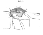
- the folded head gas bag 3 extends from the vehicle A pillar to the vehicle B pillar and is attached to two, at its two outer, upper ends when unfolded 7 locations attached to the roof frame 5, as Fig. 2 can be seen better.
- the head gas bag 3 has this Make ear-like extensions with eyelets which can be screwed into the roof frame 5, shown in FIG. 3 Extend screws 15.
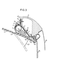
- a gas generator 11 extends in the longitudinal direction of the folded head gas bag 3 approximately the middle third of the head gas bag 3 and is attached to the roof frame 5 by means of a mounting plate 9 what is clearly shown in Fig. 3.
- the gas generator 11, which is inside the Head gas bag 3 is arranged, a cylindrical outer contour with numerous, on its outer circumferential surface distributed gas outflow openings 33, which a folded Area of the head gas bag 3 are facing.
- An on the circumferential surface of the molded stud 39 with a External thread extends through an opening in the head gas bag 3 outwards and further through an opening in a Y-shaped mounting plate 9.
- a web of the mounting plate 9, on which the gas generator 11 via its stud 39 attached by a nut 41 is in shape the outer contour of the gas generator 11 adapted and surrounding this partially so that when the nut 41 is tightened Gas generator 11 pressed against the web of the mounting plate 9 is, whereby the opening in the head gas bag 3 in the area of Stud 39 is sealed against gas escape.
- the side impact protection device 1 is simply as a completely pre-assembled unit on the roof frame 5 screwable, the pre-assembly on the one hand by the Stud 39 and the other through a mounting plate 9, the folded head gas bag 3 and the gas generator 11 surrounding film 2 takes place.
- the trim part 17, under the side impact protection device 1 does not from the outside is arranged visibly, is partially designed as a flap 19 which is caused by the unfolding process of the head gas bag 3 can be opened.
- the flap 19 is U-shaped running predetermined breaking point 21 in the trim part 17th educated.
- Edge of the flap 19 is in a rail-shaped, on the roof frame 5 latched holding part 43 latched.
- An institution to limit the maximum opening angle of the flap 19 in The shape of a tether 27 is on the one hand on the flap 19 and on the other hand fastened to the roof frame 5 by means of a screw 23, the opened flap 19 in Fig. 3 with dash-dotted lines Lines is indicated.
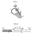
- Fig. 4 shows a second embodiment of the complete Unit of pre-assembled side impact protection device 1, in which also the mounting plate 9 within the head gas bag 3 is arranged by being in the form of a ring extends the gas generator 11 around.
- a screw-nut connection consisting of a screw 37 and a nut 35, serves on the one hand as a device for fastening the mounting plate 9 on an outside of the head gas bag 3 Adapter plate 29 and on the other hand as a device for Clamping the mounting plate 9 in the form of a clamp.
- the head of the screw 37 with the mounting plate 9 welded.
- An associated screw shaft extends through an opening in the mounting plate 9 and in the head gas bag 3 outwards and further through an opening in the adapter plate 29.
- the mounting plate 9 together with the head gas bag 3 against the adapter plate 29 pressed and fixed to her, creating the opening in the head gas bag 3 does not allow leakage gas flows.
- the adapter plate 29 is the adapter plate 29 and thus the whole Side impact protection device 1 on roof frame 5 screwed.
- For better assembly and easier transportation surrounds a thin, slotted plastic tube 28 den folded head gas bag 3 and thus the gas generator 11 and partly also the adapter plate 29.
- the head gas bag 3 is in the area of the mounting plate 9 and the gas generator 11 shown cut open. there can be seen that the mounting plate 9 and the adapter plate 29 not laterally up to the upper ends 7 of the head gas bag 3 runs, but only to the side Ends of the gas generator 11 extends.
- the assembly of the side impact protection device 1 as a complete Module is simply done using the two screws 13 and by subsequently screwing in screws 15 through the eyelets in the roof frame 5.
- the head gas bag 3 Since the head gas bag 3 is unfolded in the longitudinal direction, ie in its entire longitudinal extent is already fixed in the vehicle is locked, there is a stable airbag position in the unfolded condition.
- the unfolding itself becomes one Side impact by igniting the gas generator 11 located initiated pyrotechnic material, whereupon gas via the gas outflow openings 33 from the gas generator 11 flows out and unfolds the head gas bag 3, whereupon the flap 19 pops out of the holder part 43 and so far in Opens up towards the center of the vehicle, like the tether 27 allowed.
- the geometry of the flap 19 and its maximum opening angle are matched to the head gas bag 3 that the flap 19 the direction of deployment of the head gas bag 3 directs obliquely towards a side window 25.
- head gas bag 3 When full unfolded head gas bag 3 is a space between the opened flap 19 and the side window 25 through the Head gas bag 3 filled.
- the head gas bag 3 extends immediately adjacent to the side window 25 down and can partially support it.
- the head gas bag 3 itself due to its fixed position in the longitudinal direction mainly just down and towards Unfold the head of a vehicle occupant, resulting in a quick, unfolding which is easy to predetermine is made possible.
- the Flap 19 is kept very narrow and is in the swung open Condition hardly facing inwards, so no risk of injury for the head of the vehicle occupant.
- the trim part 17, as in 6 to 8 shown, so attached to the roof frame 5 be that the head gas bag 3 during the unfolding process slides between this and the roof frame 5 and this results in a fish mouth-like opening.
- the trim part 17 is released during the unfolding process of the head gas bag 3 from the holding part 43 like that Figures 7 and 8 show. In the area outside the ends 7 however, it remains attached to the roof frame 5 via the holding part 43.
- the trim part 17 bulges somewhat inwards so that there is a wider one in the middle of the head gas bag 3 There is a slot through which the head gas bag 3 is pushed can. In this embodiment, none additional tear-open devices needed.
Landscapes
- Engineering & Computer Science (AREA)
- Mechanical Engineering (AREA)
- Air Bags (AREA)
- Body Structure For Vehicles (AREA)
- Component Parts Of Construction Machinery (AREA)
- Superstructure Of Vehicle (AREA)
Claims (10)
- Dispositif de protection contre les impacts latéraux pour occupants de véhicules, comportant un coussin à gaz de tête gonflable (3) avec lequel la tête de l'occupant vient en contact en cas d'impact latéral, et une partie de revêtement (17) sur le cadre de toit (5) d'un véhicule, le coussin à gaz de tête (3) étant agencé à l'état non déployé sous la partie de revêtement (17) dans la région du coussin à gaz de tête (3), la partie de revêtement (17) s'ouvrant dans la région du coussin à gaz de tête (3) par le déploiement du coussin à gaz de tête (3) de telle sorte que la partie de revêtement (17) oriente le coussin à gaz de tête (3) en cours de déploiement en biais en direction de la vitre latérale (25), caractérisé en ce que le coussin à gaz de tête (3) est agencé au-dessous de la partie de revêtement (17), en étant plié sur tout son long et non-plié en direction longitudinale, et fixé au cadre de toit (5) en au moins deux points situés à ses deux extrémités (7) extérieures qui sont ses extrémités supérieures à l'état déployé.
- Dispositif de protection contre les impacts latéraux selon la revendication 1, caractérisé en ce que la partie de revêtement (17) comprend dans la partie de coussin à gaz de tête (3) un clapet (19) qui s'ouvre au cours du déploiement du coussin à gaz de tête (3).
- Dispositif de protection contre les impacts latéraux selon la revendication 2, caractérisé en ce que le clapet (19) est formé par des points destinés à la rupture (21) dans la partie de revêtement (17).
- Dispositif de protection contre les impacts latéraux selon la revendication 2 ou 3, caractérisé en ce que dans la partie de revêtement (17) est défini un axe de pivotement prédéterminé pour pivoter le clapet (19) vers le bas.
- Dispositif de protection contre les impacts latéraux selon la revendication 4, caractérisé en ce que l'axe de pivotement est un renfoncement dans la partie de revêtement (17).
- Dispositif de protection contre les impacts latéraux selon l'une des revendications 2 à 5, caractérisé en ce qu'il est prévu un dispositif pour limiter l'angle d'ouverture maximum du clapet (19).
- Dispositif de protection contre les impacts latéraux selon la revendication 6, caractérisé en ce que le dispositif comprend au moins une bande de garde (27) qui est fixée d'une part au clapet (19) et d'autre part au cadre de toit (5).
- Dispositif de protection contre les impacts latéraux selon l'une des revendications 2 à 7, caractérisé en ce que la géométrie du clapet (19) et son angle d'ouverture maximum sont adaptés au coussin à gaz de tête (3) de telle manière que le clapet (19) oriente la direction de déploiement du coussin à gaz de tête (3) en biais en direction de la vitre latérale (25).
- Dispositif de protection contre les impacts latéraux selon la revendication 1, caractérisé en ce que la partie de revêtement (17) est fixée sur le cadre de toit (5) de telle sorte qu'au cours du déploiement, le coussin à gaz de tête (3) peut passer entre la partie de revêtement (17) et le cadre de toit (5).
- Dispositif de protection contre les impacts latéraux selon la revendication 9, caractérisé en ce qu'il est prévu une partie de retenue (43) fixée sur le cadre de toit (5), laquelle retient le bord côté toit de la partie de revêtement (17), la partie de revêtement (17) se détachant de la partie de retenue (43) au cours du déploiement du coussin à gaz de tête (3).
Applications Claiming Priority (3)
| Application Number | Priority Date | Filing Date | Title |
|---|---|---|---|
| DE29603316U DE29603316U1 (de) | 1996-02-23 | 1996-02-23 | Seitenaufprall-Schutzeinrichtung für Fahrzeuginsassen |
| DE29603316U | 1996-02-23 | ||
| EP97102307A EP0791511B2 (fr) | 1996-02-23 | 1997-02-13 | Dispositif de protection des passagers d'un véhicule contre les chocs latéraux |
Related Parent Applications (1)
| Application Number | Title | Priority Date | Filing Date |
|---|---|---|---|
| EP97102307A Division EP0791511B2 (fr) | 1996-02-23 | 1997-02-13 | Dispositif de protection des passagers d'un véhicule contre les chocs latéraux |
Publications (2)
| Publication Number | Publication Date |
|---|---|
| EP0962364A1 EP0962364A1 (fr) | 1999-12-08 |
| EP0962364B1 true EP0962364B1 (fr) | 2003-07-30 |
Family
ID=8019997
Family Applications (3)
| Application Number | Title | Priority Date | Filing Date |
|---|---|---|---|
| EP97102307A Expired - Lifetime EP0791511B2 (fr) | 1996-02-23 | 1997-02-13 | Dispositif de protection des passagers d'un véhicule contre les chocs latéraux |
| EP99116167A Expired - Lifetime EP0962364B1 (fr) | 1996-02-23 | 1997-02-13 | Dispositif de protection contre les chocs latéraux |
| EP99116168A Expired - Lifetime EP0957011B1 (fr) | 1996-02-23 | 1997-02-13 | Dispositif de protection contre les chocs latéraux |
Family Applications Before (1)
| Application Number | Title | Priority Date | Filing Date |
|---|---|---|---|
| EP97102307A Expired - Lifetime EP0791511B2 (fr) | 1996-02-23 | 1997-02-13 | Dispositif de protection des passagers d'un véhicule contre les chocs latéraux |
Family Applications After (1)
| Application Number | Title | Priority Date | Filing Date |
|---|---|---|---|
| EP99116168A Expired - Lifetime EP0957011B1 (fr) | 1996-02-23 | 1997-02-13 | Dispositif de protection contre les chocs latéraux |
Country Status (5)
| Country | Link |
|---|---|
| EP (3) | EP0791511B2 (fr) |
| JP (1) | JP2791321B2 (fr) |
| CZ (1) | CZ53297A3 (fr) |
| DE (4) | DE29603316U1 (fr) |
| ES (3) | ES2177180T3 (fr) |
Families Citing this family (40)
| Publication number | Priority date | Publication date | Assignee | Title |
|---|---|---|---|---|
| JP3175582B2 (ja) * | 1996-03-25 | 2001-06-11 | トヨタ自動車株式会社 | 乗員保護装置 |
| DE19612228A1 (de) | 1996-03-27 | 1997-10-02 | Bayerische Motoren Werke Ag | Aufblasbares Kopfschutzsystem für den Seitenbereich eines Personenkraftwagens |
| DE19612227A1 (de) * | 1996-03-27 | 1997-10-02 | Bayerische Motoren Werke Ag | Anordnung eines aufblasbaren Kopfschutzsystemes in einem Kraftfahrzeug |
| DE19612229A1 (de) * | 1996-03-27 | 1997-10-02 | Bayerische Motoren Werke Ag | Anordnung eines aufblasbaren seitlichen Kopfschutzsystemes in einem Kraftfahrzeug |
| JP3427289B2 (ja) * | 1996-05-30 | 2003-07-14 | 豊田合成株式会社 | ガーニッシュ |
| DE19642964A1 (de) * | 1996-10-18 | 1998-04-23 | Happich Gmbh Gebr | Airbagvorrichtung |
| DE69732261T2 (de) | 1996-11-07 | 2005-12-29 | Toyoda Gosei Co., Ltd., Haruhi | Anordnung und Konstruktion einer Kraftfahrzeug-Insassenschutzvorrichtung |
| GB2319751B (en) * | 1996-11-22 | 2001-04-04 | Autoliv Dev | Improvements in or relating to an air-bag arrangement |
| DE19752989B4 (de) * | 1996-12-02 | 2005-11-10 | Toyoda Gosei Co., Ltd. | Seitenairbag-Vorrichtung |
| EP0855315B1 (fr) * | 1997-01-24 | 2002-04-10 | Breed Automotive Technology, Inc. | Dispositf de coussin gonflable |
| DE19704195C1 (de) * | 1997-02-05 | 1998-10-22 | Brocke Kg I B S | Säulenverkleidung für Säulen von Kraftfahrzeugen |
| JP2920291B2 (ja) | 1997-08-28 | 1999-07-19 | トヨタ自動車株式会社 | 頭部保護エアバッグ装置 |
| DE29716793U1 (de) * | 1997-09-18 | 1998-01-22 | Trw Occupant Restraint Systems Gmbh, 73551 Alfdorf | Gassack-Rückhaltesystem für Fahrzeuginsassen |
| DE29716574U1 (de) * | 1997-09-15 | 1998-01-22 | Trw Occupant Restraint Systems Gmbh, 73551 Alfdorf | Dachhimmel-Verkleidung mit integrierten Kopfschutz-Gassackmodulen |
| EP0903269B1 (fr) | 1997-09-18 | 2002-10-02 | DaimlerChrysler AG | Module de coussin gonflable dans un véhicule |
| DE19848794A1 (de) * | 1997-10-22 | 1999-05-27 | Inova Gmbh Tech Entwicklungen | Airbagvorrichtung, Herstellungsverfahren für eine Airbagvorrichtung, Auslöseverfahren für eine Airbagvorrichtung und Kraftfahrzeug mit einer Airbagvorrichtung |
| US6340171B1 (en) | 1997-10-29 | 2002-01-22 | Daimlerchrysler Ag | Air bag module in a motor vehicle |
| DE29720619U1 (de) | 1997-11-20 | 1999-05-12 | Lear Corp Gmbh & Co Kg | Seitenaufprall-Schutzeinrichtung |
| DE19754137A1 (de) * | 1997-12-05 | 1999-06-10 | Bayerische Motoren Werke Ag | Verkleidungsteil für einen Airbag in einem Kraftfahrzeug |
| US6070902A (en) * | 1998-02-12 | 2000-06-06 | Lear Corporation | Vehicle interior headliner system |
| JP3104668B2 (ja) * | 1998-03-18 | 2000-10-30 | トヨタ自動車株式会社 | 車両用頭部保護エアバッグ装置 |
| DE19815381C5 (de) * | 1998-04-06 | 2004-04-22 | Breed Automotive Technology, Inc., Lakeland | Dachhimmelverkleidung |
| JP3093199B2 (ja) * | 1998-05-12 | 2000-10-03 | トヨタ自動車株式会社 | 頭部保護エアバッグ装置の配設構造 |
| FR2783474B1 (fr) | 1998-09-21 | 2001-02-16 | Renault | Procede de montage de sacs gonflables de protection laterale des passagers d'un vehicule automobile |
| DE19856623A1 (de) * | 1998-12-08 | 2000-06-15 | Imeco Einwegprodukte Gmbh & Co | Airbag-Umkleidung |
| DE29915820U1 (de) | 1999-09-08 | 2000-01-13 | TRW Occupant Restraint Systems GmbH & Co. KG, 73553 Alfdorf | Seitenaufprall-Schutzeinrichtung |
| FR2798339B1 (fr) | 1999-09-10 | 2001-10-05 | Renault | Dispositif d'aide au deploiement d'un coussin gonflable de vehicule automobile |
| EP1237765B1 (fr) | 1999-12-17 | 2005-04-13 | Lear Corporation | Ensemble garniture de pavillon modulaire comportant des rideaux d'air |
| DE10001387C2 (de) * | 2000-01-14 | 2003-12-24 | Imeco Einwegprodukte Gmbh & Co | Airbag-Schutzhülle |
| DE10042419A1 (de) | 2000-08-30 | 2002-03-14 | Daimler Chrysler Ag | Dachverkleidung für einen Innenraum eines Fahrzeuges mit einem Seitenaufprallschutz |
| DE20105734U1 (de) | 2001-04-02 | 2001-08-30 | Trw Repa Gmbh | Gassackmodul für ein Fahrzeuginsassen-Rückhaltesystem |
| DE10130688B4 (de) * | 2001-06-26 | 2007-09-27 | Imeco Einwegprodukte Gmbh + Co. | Airbag-Schutzhülle |
| DE102004007282A1 (de) * | 2004-02-14 | 2005-09-08 | Daimlerchrysler Ag | Dachverkleidung |
| DE102004007415B4 (de) * | 2004-02-16 | 2006-02-09 | Key Safety Systems, Inc.(n.d.Ges.d.Staates Delaware), Sterling Heights | Befestigung für einen Gassack |
| US7097200B2 (en) | 2004-04-12 | 2006-08-29 | Autoliv Asp, Inc. | Inflatable curtain trajectory bracket |
| DE102005014087A1 (de) * | 2005-03-22 | 2006-10-19 | Takata-Petri (Ulm) Gmbh | Dachhimmelmodul und Verfahren zur Montage eines Airbagmoduls in einem Kraftfahrzeug |
| DE102005061544B4 (de) * | 2005-12-22 | 2016-12-15 | Bayerische Motoren Werke Aktiengesellschaft | Dachhimmel für einen Fahrzeuginnenraum eines Kraftfahrzeugs |
| DE102006055723B4 (de) * | 2006-11-25 | 2015-11-12 | Autoliv Development Ab | Airbaganordnung mit einem innenseitig des Gassackes befestigten Gasgenerator |
| DE102007032712B4 (de) | 2007-07-13 | 2016-11-24 | GM Global Technology Operations LLC (n. d. Ges. d. Staates Delaware) | Kraftfahrzeuginneneinrichtung mit einem Innenverkleidungsteil mit einer Austrittsöffnung für einen Gassack |
| DE102007033743B4 (de) * | 2007-07-18 | 2018-05-09 | Volkswagen Ag | Airbagabdeckung insbesondere für einen Kopfairbag, in einem Fahrzeug |
Family Cites Families (12)
| Publication number | Priority date | Publication date | Assignee | Title |
|---|---|---|---|---|
| DE2249988A1 (de) | 1972-10-12 | 1974-04-18 | Porsche Ag | Rueckhaltevorrichtung fuer kraftfahrzeuge |
| IT1061177B (it) * | 1976-03-25 | 1982-10-20 | Exacon Int | Dispositivo protettivo per la testa di automobilisti |
| DE3422263A1 (de) | 1984-06-15 | 1985-12-19 | Audi AG, 8070 Ingolstadt | Sicherheitseinrichtung zum schutz von fahrzeuginsassen bei einem seitenaufprall |
| GB2191450A (en) * | 1986-06-14 | 1987-12-16 | Britax P M G Ltd | Inflatable vehicle occupant protection |
| JP3107383B2 (ja) * | 1990-03-26 | 2000-11-06 | マツダ株式会社 | 車体側部のエネルギ吸収構造 |
| JP3039089B2 (ja) * | 1991-11-22 | 2000-05-08 | タカタ株式会社 | 自動車の乗員頭部の保護装置 |
| US5480181A (en) † | 1993-02-19 | 1996-01-02 | Simula Inc. | Side impact head strike protection system |
| JPH07117605A (ja) * | 1993-10-27 | 1995-05-09 | Honda Motor Co Ltd | 自動車用エアバッグ装置 |
| DE4426848A1 (de) * | 1994-07-28 | 1996-02-01 | Hs Tech & Design | Airbagvorrichtung |
| US5602734A (en) * | 1994-09-23 | 1997-02-11 | Advanced Safety Concepts, Inc. | Automobile air bag systems |
| US5540459A (en) * | 1994-10-05 | 1996-07-30 | Ford Motor Company | Roof rail mounted airbag assembly |
| US5470103A (en) † | 1994-12-27 | 1995-11-28 | Davidson Textron Inc. | Motor vehicle head impact air bag system |
-
1996
- 1996-02-23 DE DE29603316U patent/DE29603316U1/de not_active Expired - Lifetime
-
1997
- 1997-02-13 ES ES99116168T patent/ES2177180T3/es not_active Expired - Lifetime
- 1997-02-13 ES ES99116167T patent/ES2204037T3/es not_active Expired - Lifetime
- 1997-02-13 DE DE59702581T patent/DE59702581D1/de not_active Expired - Lifetime
- 1997-02-13 DE DE59710519T patent/DE59710519D1/de not_active Expired - Lifetime
- 1997-02-13 EP EP97102307A patent/EP0791511B2/fr not_active Expired - Lifetime
- 1997-02-13 EP EP99116167A patent/EP0962364B1/fr not_active Expired - Lifetime
- 1997-02-13 ES ES97102307T patent/ES2107402T3/es not_active Expired - Lifetime
- 1997-02-13 EP EP99116168A patent/EP0957011B1/fr not_active Expired - Lifetime
- 1997-02-13 DE DE59707119T patent/DE59707119D1/de not_active Expired - Lifetime
- 1997-02-21 CZ CZ97532A patent/CZ53297A3/cs unknown
- 1997-02-21 JP JP9038070A patent/JP2791321B2/ja not_active Expired - Lifetime
Also Published As
| Publication number | Publication date |
|---|---|
| EP0791511A1 (fr) | 1997-08-27 |
| EP0957011A1 (fr) | 1999-11-17 |
| ES2107402T3 (es) | 2001-02-16 |
| EP0962364A1 (fr) | 1999-12-08 |
| DE59710519D1 (de) | 2003-09-04 |
| DE29603316U1 (de) | 1996-06-20 |
| DE59707119D1 (de) | 2002-05-29 |
| ES2177180T3 (es) | 2002-12-01 |
| JPH09226504A (ja) | 1997-09-02 |
| EP0957011B1 (fr) | 2002-04-24 |
| ES2107402T1 (es) | 1997-12-01 |
| DE59702581D1 (de) | 2000-12-14 |
| EP0791511B1 (fr) | 2000-11-08 |
| JP2791321B2 (ja) | 1998-08-27 |
| EP0791511B2 (fr) | 2004-02-04 |
| ES2204037T3 (es) | 2004-04-16 |
| CZ53297A3 (en) | 1997-09-17 |
Similar Documents
| Publication | Publication Date | Title |
|---|---|---|
| EP0957011B1 (fr) | Dispositif de protection contre les chocs latéraux | |
| EP1048531B1 (fr) | Dispositif de protection contre le choc latéral pour les occupants d'un véhicule | |
| EP0957008B1 (fr) | Dispositif de protection à l'égard d' impacts latéraux | |
| DE19815381C2 (de) | Dachhimmelverkleidung | |
| DE10224726B4 (de) | Airbag-Halteklammer | |
| DE69827452T2 (de) | Plazierungsanordnung für einen kopfschützenden Luftsack | |
| DE69004355T2 (de) | Leichtbaugehäuse für Aufblasvorrichtungen auf der Beifahrerseite. | |
| DE10004483C2 (de) | Airbagvorrichtung zur Anordnung im Dachrahmenbereich eines Kraftfahrzeuges | |
| DE19758754B4 (de) | Abdeckung für ein fahrerseitiges Airbagmodul | |
| DE69816572T2 (de) | Airbagsystem für Kraftfahrzeuge und Verfahren zur Steuerung dieses Systems | |
| DE69616646T2 (de) | Abbrechbares Befestigungssystem für Luftsackentfaltungsdeckel | |
| DE10000768B4 (de) | Aufblasbare Seitenvorhanganordnung für ein Fahrzeug | |
| EP1732787B2 (fr) | Habillage interieur de portiere comprenant un airbag anti-choc tete et/ou epaules en cas de collision laterale et/ou un recouvrement, et portiere de vehicule presentant un tel habillage interieur | |
| EP1083100B1 (fr) | Système de protection en cas de choc latéral | |
| WO2000037286A2 (fr) | Module d'habillage pour automobile | |
| EP1660356B1 (fr) | Boitier pour systeme d'airbag | |
| DE19932949A1 (de) | Vehicle Headliner With Inflatable Side Curtain | |
| DE10020929C5 (de) | Airbagmodul | |
| DE19745872B4 (de) | Airbageinrichtung | |
| DE10059224B4 (de) | Sicherheitsreinrichtung für ein Kraftfahrzeug zum Schutz von Fußgängern | |
| DE69514626T2 (de) | Entfaltungsdeckel zum Gebrauch in einer Fahrzeuginsassen-Rückhaltevorrichtung | |
| DE102004026313A1 (de) | Überkopf-Airbagsystem | |
| EP0816180A1 (fr) | Coussin de sécurité gonflable pour véhicule | |
| DE20015135U1 (de) | Gassack-Rückhaltesystem | |
| DE19633696B4 (de) | Airbagabdeckklappe |
Legal Events
| Date | Code | Title | Description |
|---|---|---|---|
| PUAI | Public reference made under article 153(3) epc to a published international application that has entered the european phase |
Free format text: ORIGINAL CODE: 0009012 |
|
| AC | Divisional application: reference to earlier application |
Ref document number: 791511 Country of ref document: EP |
|
| AK | Designated contracting states |
Kind code of ref document: A1 Designated state(s): DE ES FR GB IT SE |
|
| 17P | Request for examination filed |
Effective date: 20000608 |
|
| AKX | Designation fees paid |
Free format text: DE ES FR GB IT SE |
|
| 17Q | First examination report despatched |
Effective date: 20010726 |
|
| GRAH | Despatch of communication of intention to grant a patent |
Free format text: ORIGINAL CODE: EPIDOS IGRA |
|
| GRAH | Despatch of communication of intention to grant a patent |
Free format text: ORIGINAL CODE: EPIDOS IGRA |
|
| GRAA | (expected) grant |
Free format text: ORIGINAL CODE: 0009210 |
|
| AC | Divisional application: reference to earlier application |
Ref document number: 0791511 Country of ref document: EP Kind code of ref document: P |
|
| AK | Designated contracting states |
Designated state(s): DE ES FR GB IT SE |
|
| REG | Reference to a national code |
Ref country code: GB Ref legal event code: FG4D Free format text: NOT ENGLISH |
|
| REF | Corresponds to: |
Ref document number: 59710519 Country of ref document: DE Date of ref document: 20030904 Kind code of ref document: P |
|
| PG25 | Lapsed in a contracting state [announced via postgrant information from national office to epo] |
Ref country code: SE Free format text: LAPSE BECAUSE OF FAILURE TO SUBMIT A TRANSLATION OF THE DESCRIPTION OR TO PAY THE FEE WITHIN THE PRESCRIBED TIME-LIMIT Effective date: 20031030 |
|
| GBT | Gb: translation of ep patent filed (gb section 77(6)(a)/1977) |
Effective date: 20031113 |
|
| PG25 | Lapsed in a contracting state [announced via postgrant information from national office to epo] |
Ref country code: GB Free format text: LAPSE BECAUSE OF NON-PAYMENT OF DUE FEES Effective date: 20040213 |
|
| REG | Reference to a national code |
Ref country code: ES Ref legal event code: FG2A Ref document number: 2204037 Country of ref document: ES Kind code of ref document: T3 |
|
| ET | Fr: translation filed | ||
| PLBE | No opposition filed within time limit |
Free format text: ORIGINAL CODE: 0009261 |
|
| STAA | Information on the status of an ep patent application or granted ep patent |
Free format text: STATUS: NO OPPOSITION FILED WITHIN TIME LIMIT |
|
| 26N | No opposition filed |
Effective date: 20040504 |
|
| GBPC | Gb: european patent ceased through non-payment of renewal fee |
Effective date: 20040213 |
|
| PGFP | Annual fee paid to national office [announced via postgrant information from national office to epo] |
Ref country code: ES Payment date: 20090218 Year of fee payment: 13 |
|
| REG | Reference to a national code |
Ref country code: ES Ref legal event code: FD2A Effective date: 20110328 |
|
| PG25 | Lapsed in a contracting state [announced via postgrant information from national office to epo] |
Ref country code: ES Free format text: LAPSE BECAUSE OF NON-PAYMENT OF DUE FEES Effective date: 20110314 |
|
| PG25 | Lapsed in a contracting state [announced via postgrant information from national office to epo] |
Ref country code: ES Free format text: LAPSE BECAUSE OF NON-PAYMENT OF DUE FEES Effective date: 20100214 |
|
| REG | Reference to a national code |
Ref country code: FR Ref legal event code: PLFP Year of fee payment: 20 |
|
| PGFP | Annual fee paid to national office [announced via postgrant information from national office to epo] |
Ref country code: IT Payment date: 20160223 Year of fee payment: 20 Ref country code: DE Payment date: 20160229 Year of fee payment: 20 |
|
| PGFP | Annual fee paid to national office [announced via postgrant information from national office to epo] |
Ref country code: FR Payment date: 20160217 Year of fee payment: 20 |
|
| REG | Reference to a national code |
Ref country code: DE Ref legal event code: R071 Ref document number: 59710519 Country of ref document: DE |