EP0962607A1 - Dispositif dispensateur pour adhésif à prise directe - Google Patents
Dispositif dispensateur pour adhésif à prise directe Download PDFInfo
- Publication number
- EP0962607A1 EP0962607A1 EP98110375A EP98110375A EP0962607A1 EP 0962607 A1 EP0962607 A1 EP 0962607A1 EP 98110375 A EP98110375 A EP 98110375A EP 98110375 A EP98110375 A EP 98110375A EP 0962607 A1 EP0962607 A1 EP 0962607A1
- Authority
- EP
- European Patent Office
- Prior art keywords
- adhesive
- cylinder channel
- screw
- worm
- head
- Prior art date
- Legal status (The legal status is an assumption and is not a legal conclusion. Google has not performed a legal analysis and makes no representation as to the accuracy of the status listed.)
- Withdrawn
Links
- 239000000853 adhesive Substances 0.000 title claims description 122
- 230000001070 adhesive effect Effects 0.000 title claims description 122
- 241000237858 Gastropoda Species 0.000 claims description 26
- 239000012790 adhesive layer Substances 0.000 claims description 4
- 230000010006 flight Effects 0.000 claims description 3
- 238000004804 winding Methods 0.000 abstract 1
- 238000003860 storage Methods 0.000 description 8
- 238000009408 flooring Methods 0.000 description 6
- 239000003292 glue Substances 0.000 description 6
- 238000010438 heat treatment Methods 0.000 description 5
- 238000000034 method Methods 0.000 description 4
- 238000007599 discharging Methods 0.000 description 3
- 230000005484 gravity Effects 0.000 description 3
- 230000002028 premature Effects 0.000 description 3
- 230000001960 triggered effect Effects 0.000 description 3
- 238000003780 insertion Methods 0.000 description 2
- 230000037431 insertion Effects 0.000 description 2
- 230000002093 peripheral effect Effects 0.000 description 2
- 241000554155 Andes Species 0.000 description 1
- 238000004026 adhesive bonding Methods 0.000 description 1
- 230000005540 biological transmission Effects 0.000 description 1
- 238000004140 cleaning Methods 0.000 description 1
- 238000001514 detection method Methods 0.000 description 1
- 230000000694 effects Effects 0.000 description 1
- 238000009434 installation Methods 0.000 description 1
- 230000003993 interaction Effects 0.000 description 1
- 239000000463 material Substances 0.000 description 1
- 238000011089 mechanical engineering Methods 0.000 description 1
- 239000002184 metal Substances 0.000 description 1
- 235000011837 pasties Nutrition 0.000 description 1
- 238000007789 sealing Methods 0.000 description 1
- 239000007787 solid Substances 0.000 description 1
- 230000007306 turnover Effects 0.000 description 1
- 238000003466 welding Methods 0.000 description 1
Images


Classifications
-
- E—FIXED CONSTRUCTIONS
- E04—BUILDING
- E04F—FINISHING WORK ON BUILDINGS, e.g. STAIRS, FLOORS
- E04F21/00—Implements for finishing work on buildings
- E04F21/02—Implements for finishing work on buildings for applying plasticised masses to surfaces, e.g. plastering walls
- E04F21/06—Implements for applying plaster, insulating material, or the like
- E04F21/08—Mechanical implements
-
- B—PERFORMING OPERATIONS; TRANSPORTING
- B05—SPRAYING OR ATOMISING IN GENERAL; APPLYING FLUENT MATERIALS TO SURFACES, IN GENERAL
- B05C—APPARATUS FOR APPLYING FLUENT MATERIALS TO SURFACES, IN GENERAL
- B05C11/00—Component parts, details or accessories not specifically provided for in groups B05C1/00 - B05C9/00
- B05C11/10—Storage, supply or control of liquid or other fluent material; Recovery of excess liquid or other fluent material
Definitions
- the present invention relates to a device for discharging self-setting adhesive, especially for dispensing adhesive for Flooring is suitable.
- a self-setting adhesive is understood to mean an adhesive in which the setting takes place without the addition of another adhesive component (such as e.g. Harder) by itself.
- Self-setting adhesives according to this definition thus include one-component adhesives and already mixed two- or Multi-component adhesives.
- the adhesive will still be on the underlay after it has been applied has to remain processable for a while.
- the adhesive set first about 15 to 30 minutes after applying the adhesive.
- the insertion of the Setting process not only from the time since the application or - in the case of Multi-component adhesives - since mixing the adhesive off, but in to a large extent also on the way in which the adhesive is processed. So can in particular the application of pressure to the adhesive and / or the heating of the Adhesive significantly accelerate the setting process. Also adds many adhesives the setting process, if it occurs locally at one point in the Adhesive has also been used around this area. The insertion of the The setting process can then be compared to a chain reaction that is only local needs to be initialized and then spreads throughout the adhesive.
- All previously known motor-operated adhesive discharge devices are not for the discharge of self-setting adhesive for floor coverings suitable because they are used when applying the adhesives commonly used for floor coverings trigger premature setting of these adhesives.
- the premature setting will either by applying excessive pressure to the adhesive, by (e.g. frictional) heating of the adhesive or by residues in the Adhesive discharge device triggered stuck adhesive, where the Setting has already started.
- the object of the present invention is to provide a. also motorized operable device for dispensing self-setting adhesive, which at Discharge the generation of pressure on the adhesive and the heating of the Avoiding adhesive as much as possible and sticking of adhesive residues in the Discharge device largely prevented, so that the device for Discharge of adhesive is suitable for floor coverings.
- a smooth, rounded cross-sectional profile is to be understood as a cross-sectional profile whose profile line consists of round (i.e. curved) lines and at most straight lines Lines is composed, whereby according to a mathematical definition the profile line Has a graph of a continuous function with a continuous derivative. The means that the profile line has neither jumps nor corners.
- a cylindrical screw is a screw with a screw head, whose envelope has a cylindrical shape.
- the snail's head is the one Part of the worm on which at least one worm gear is formed.
- a cylinder channel is a channel with a hollow cylindrical inner surface. Under a cylindrical screw with clearance fit in a cylinder channel is an arrangement to understand from a cylindrical screw and a cylinder channel, the Snail head of the cylindrical screw with clearance fit in the cylinder channel is.
- the cylindrical screw is turned to discharge the adhesive the cylinder axis is driven to rotate in the cylinder channel.
- This will make the Adhesive from the feed chamber through the cylinder channel and then driven out of the outlet opening.
- the arrangement of cylindrical screw and Cylinder channel acts as an efficient screw conveyor.
- the snail gear is in shape a helical groove with a smooth, rounded cross-sectional profile on the cylinder surface the snail trained.
- the smooth, rounded inner surface of the groove causes the Discharge of the adhesive creating excessive pressure on the adhesive or excessive heating of the adhesive (e.g. due to friction) is largely avoided.
- the smooth round inner surface of the groove ensures Discharge of the adhesive also for a largely homogeneous flow of the Adhesive in the worm gear, so that no adhesive residue in the Discharge device get stuck.
- the cylinder channel in the feed space is preferably in the immediate vicinity of the Outlet opening is arranged. It is further preferred that the entire Cross-sectional area of the one or more assigned to the cylinder channel Outlet openings in the range between one tenth and one fiftieth of the Cross-sectional area of the cylinder duct measures. It preferably measures the whole Cross-sectional area of the outlet openings approximately 1/25 of the cross-sectional area of the Cylinder channel.
- the length of the outlet opening is advantageously in the range between in one Third and a tenth of the length of the cylinder channel. Preferably measures the length the outlet opening approximately one sixth of the cylinder channel length.
- the cylindrical screw comprises a cylindrical screw head having the worm gear and one Auger shaft with an essentially smooth surface.
- the length of the Snail head in the axial direction is advantageously in the range between half and twice the cylinder channel diameter, one approximately Cylinder channel diameter corresponding worm head length is preferred.
- the Length of the cylinder channel can range between half and double Cylinder channel diameters lie, with a length of approximately 0.8 times Diameter is preferred.
- the slope of the worm gear per turn can be between half and three times the cylinder channel diameter, one Slope of approximately 4/3 of the cylinder channel diameter is preferred.
- an arcuate can be formed along its circumference Continuation groove of the worm gear is formed.
- Another preferred embodiment of the invention is characterized in that that the screw is provided with two screw flights, which are like a Two turns are arranged.
- the adhesive discharge device according to the invention can be a number of Have snails, with adjacent snails each with counter-rotating Worm threads are formed.
- the discharge device can also comprise a motor to move the screws To drive rotation. Furthermore, the discharge device can drive means for Have moving the device on the floor, with the motor for the Worm drives are coupled to ensure a uniform discharge Allow adhesive layer on the floor.
- Adhesive discharge devices comprise a frame on which one Holding device for a containing the adhesive to be discharged Adhesive storage container is arranged.
- the holding device comprises one in the Operating position of the discharge device as the bottom of the adhesive storage container serving lid-like platform 12.
- On the frame is a discharge head 10 for Discharge of the adhesive attached.
- the floor platform 12 has approximately in the Middle of an opening, which is via a funnel-shaped adhesive feed device 14 for feeding the adhesive from the adhesive storage container to the discharge head 10 leads to the latter.
- the from the holding device, the discharge head 10 and the Adhesive feed device 14 is 180 degrees around an arrangement horizontal swivel axis pivotally arranged on the frame.
- the arrangement For loading the discharge device with a filled adhesive storage container the arrangement is pivoted in such a way that the lid-like platform 12 goes up comes to rest. An adhesive storage container is then shaped in this loading position a commercially available adhesive bucket by means of the holding device on the Discharge device attached. If the adhesive is a two or Multi-component adhesive deals with the adhesive components before Attach the bucket to the discharge device mixed. Then the Lid of the bucket removed and the bucket with the lid-like platform 12 again locked.
- the lid-like platform 12 is designed accordingly so that it for commercial glue tubs can serve as a tightly closing lid 12.
- the pivoting assembly After the glue bucket is closed with the lid-like platform 12, the pivoting assembly about 180 degrees to the operating position pivoted so that the platform 12 is now the bottom 12 of the adhesive storage container comes to lie essentially below the adhesive.
- the adhesive In this operating position the adhesive is essentially by gravity from the adhesive bucket through the Opening in the floor platform 12 and over the funnel-shaped Adhesive feed device 14 conveyed to the discharge head 10.
- the Adhesive feed device 14 opens from the rear into a rear wall of the trough-shaped housing part 18 of the discharge head 10 of the adhesive discharge device.
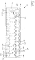
- the application head 10 shown in FIGS. 1 and 2 essentially comprises one Gear part 16, a trough-shaped housing part 18, a nozzle part 20 and thirteen Cylindrical screws 30.1 - 30.13.
- the trough-shaped housing part 18 (also in the following referred to as trough part 18) and the gear part 16 forming the cover of trough 18 define a substantially closed cavity 25, hereinafter referred to as Feed space 25 is called.
- the trough part 18 has essentially the shape of a cuboid trough with a rectangular floor plan.
- the trough part 18 has a rear wall or rear wall, two side walls, a front wall and a floor that go together to form one Trough are connected.
- the trough part 18 is made of the type customary for mechanical engineering Metal manufactured (like the case of the gear part 16, the gears 40.1 - 40.13 of the gear part 16, the nozzle part 20 and the cylindrical screws 30.1 - 30.13).
- the trough part 18 can be machined from solid, by means of welding connected walls and the floor or other suitable Be made.
- In the rear wall of the trough part 18 there are one or more Feed openings arranged on the outside of the above-mentioned Adhesive feed device 14 is connected.
- the bottom of the trough part 18 has thirteen cylindrical bores 24.1-24.13 Mistake.
- the holes 24.1 - 24.13 are essentially regular Full-length distances along the center line between the rear wall and the front wall of the trough part 18 is arranged.
- the diameter of the holes 24.1 - 24.13 is dimensioned such that the cylindrical screws described below 30.1 - 30.13 can be accommodated in the holes 24.1 - 24.13 with a clearance fit and in they are rotatably guided.
- the bores 24.1 - 24.13 have a diameter of about 18 mm.
- the bottom of the trough part 18 is approximately 15 mm thick, so it measures Length of the bores 24.1 - 24.13 or the length or height of the cylinder channels 24.1 - 24.13 also about 15 mm.
- the holes 24.1 - 24.13 in the trough bottom serve as Cylinder channel 24.1 - 24.13 for the cylindrical screws 30.1 - 30.13 to in Interaction with these as a means of conveying the adhesive from the To serve feed chamber 25 in the discharge head 10.
- the feed space 25 of the discharge head 10 is through the one cover for the Trough-forming gear part 16 completed.
- the gear part 16 includes a cuboid gearbox, in the hollow interior in a row along the longitudinal center line of the gear housing the upper ends of the Worm shafts 38.1 - 38.13 are each rotatably mounted about the worm axis.
- On each worm shaft 38.1 - 38.13 has an identical gear 40.1 - 40.13 rotatably appropriate.
- the gears 40.1 - 40.13 from adjacent worm shafts 38.1 - 38.13 are engaged with each other.
- the Gear arrangement is one of the worm shafts with an extension upwards provided which is guided as a shaft journal 45 through the gear housing and so forms a drive shaft 45 on the top of the transmission housing.
- This Drive shaft 45 is suitable for the operation of the discharge device Drive means driven to rotate, causing the cylindrical screws 30.1 - 30.13 in the discharge head 10 are set in rotation and thereby expelling the Effect glue.
- a plate-shaped nozzle part 20 is attached to the underside of the trough part 18, which forms the lower end of the discharge head 10.
- the nozzle part 20 is with twenty six identical holes 22.1 - 22.26 provided as Outlet openings 22.1 - 22.26 or outlet nozzles 22.1 - 22.26 for the adhesive to serve.
- the Bores or nozzles 22.1 - 22.26 along the longitudinal parallel center line of the Nozzle part 20 arranged.
- In the assembled discharge head 10 are each two outlet nozzles 22.1, 22.2 directly below a cylinder channel 24.1 on one Diameter of the cylinder channel 24.1 and symmetrical with respect to the axis of the Cylinder channel 24.1 arranged.
- the plate-shaped nozzle part 20 has a thickness of about 3 mm.
- the length of the nozzles 22.1-22.26 thus also measures approximately 3 mm.
- the diameter of the bores 22.1-22.26 forming the outlet nozzles is attributed to the embodiment shown in Figures 1 and 2 about 2.5 mm.
- the gear part 16, the trough part 18 and the nozzle part 20 are by means of Screw connections optionally releasably connected to each other. This will make a ensures easy disassembly of the discharge head 10 for cleaning purposes.
- the cylindrical screws 30.1 - 30.13 each have a screw shaft 38 with substantially smooth surface and a cylindrical screw head 32, in which one or more worm threads are formed.
- the worm shaft 38 and the screw head 32 are firmly connected.
- the exemplary embodiments shown are those of screw head 32 and shaft 38 existing screws 30.1 - 30.13 each made in one piece. With others However, embodiments of the invention can also be made of screws 30.1-30.13 be composed of several pieces.
- the upper ends of the screw shafts in the operating state of the discharge device 38 are rotatably supported in the gear part 16 of the discharge head 10 and are by the gear assembly is driven to rotate.
- the middle part of the Worm shafts 38 extend essentially over the entire height of the feed space 25 in the discharge head 10.
- a cylindrical screw head 32 is arranged in each case. Each screw head 32 rotates with clearance fit essentially without contact in a hole 24.1 - 24.13 assigned cylinder channel 24.1 formed in the bottom of the trough part 18 24.13, the front lower end of the screw head 32 being slightly Distance rotates essentially without contact over the plate-shaped nozzle part 20.
- Adjacent snails 30.1 - 30.13 (which, as mentioned above, are in opposite directions turn) are each provided with counter-rotating worm threads on the worm head 32, so that when the discharge device is driven, the adhesive is in relation to the respective Convey parallel screw axes in the same axial direction.
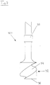
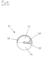
- FIGS. 3 and 4 show a first embodiment of a cylindrical screw 30.1 for an adhesive discharge device according to the invention is shown.
- the cylindrical Screw head 32 of the cylindrical screw 30.1 shown in FIGS. 3 and 4 is provided with only a single worm gear 34.
- the worm gear 34 in Form of a helical groove 34 formed on the peripheral wall of the cylinder has a smooth, rounded cross-sectional profile.
- the profile line of this cross section is U-shaped with a semicircular base section on the Groove base and two straight side sections connecting without kinks.
- the semicircular arc of the base section has a radius of approximately 4 mm.
- the Andes Semi-circular arc connecting straight side sections of the groove cross-section profile are approximately 2 mm high.
- cylindrical screw head 32 has a height or a length in the axial direction of about 18 mm and also about 18 mm in diameter.
- the slope of the worm gear 34 is approximately 24 mm per turn.
- the weird one Worm gear 34 thus only extends for approximately 3 ⁇ 4 of a full circumference the cylindrical outer surface of the screw head 32.
- the length of the screw head 32 is somewhat larger than the length of the cylinder channel 24.1, in which the screw head 32 is rotatably arranged with a clearance fit.
- the screw head 32 stands a little (in the one shown in the figures Embodiments by about 3 mm) over the upper edge of the cylinder channel 24.1 into the feed space 25 of the discharge device. This will make the Detection of the adhesive present in the feed space 25 through the screw flight 34 relieved when the screw 30.1 are rotating.
- the worm gear 34 shown in FIGS. 3 and 4 has at the bottom Snail head 32, following the oblique worm gear 34 with constant Slope, a substantially horizontal continuation 35 in the lower Front side 36 of the screw head 32.
- the groove 35 in the end face 36 of the Auger head 32 formed continuation path 35 leads in an arc for approximately half a circle around the outer circumference of the cylindrical screw head 32 along.
- the boundary between the oblique worm gear 34 and the horizontal continuation path 35 marked with a broken line.
- the profile line of the horizontal continuation path 35 in the lower end face 36 of the Snail head 32 is circular arc shaped with a radius of approximately 3 mm and a maximum depth of the groove 35 in the end face 36 of approximately 2 mm. Between the outside of the groove 35 and the circumferential side of the cylinder Snail head 32 becomes an approximately 2 mm thick edge 39 of the flat, original circular end face 36 left.
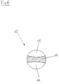
- FIGS. 5 and 6 show a second embodiment of a cylindrical screw 60 for an adhesive discharge device according to the invention is shown.
- the cylindrical The screw head 62 of the cylindrical screw 60 shown in FIGS. 5 and 6 is included two worm gears 64, 65 provided in the form of a double turn in the form of grooves 64, 65 formed on the peripheral wall of the cylinder.
- the grooves 64, 65 each have an identical smooth, round cross-sectional profile.
- the Profile line of this cross section is U-shaped with a semicircular base section at the groove base and two kink-free subsequent straight side sections.
- the semicircular arch of the Base section has a radius of approximately 3 mm.
- the on the semicircular arch adjoining rectilinear side sections of the groove cross-sectional profile about 3 mm high.
- Screw head 62 has a height or length in the axial direction of approximately 18 mm and also a diameter of approximately 18 mm.
- the constant slope of the Worms 64, 65 are approximately 22 mm per turn.
- the weird ones Worms 64, 65 thus run for approximately 9/11 of a full circumference on the cylindrical outer surface of the screw head 62.
- FIGS. 5 and 6 they are in the manner of a Double turn arranged worm threads 64, 65 with a constant pitch formed down to the lower string side 66 of the snail's head, where they in In contrast to the embodiment shown in FIGS. 3 and 4, none have horizontal continuation. This will on the lower front of the cylindrical worm head substantially along a diameter web-shaped part 66 of the flat, originally circular end face 66 of the Leave snail head 62 (shown hatched in FIG. 6). The rest of originally circular flat end face is missing due to that in the screw head 62 formed grooves 64, 65.
- the width of the web 66 is such on the diameter the outlet nozzles in the nozzle part below the screw head 62 adapted that in a certain rotational position of the screw head 62 of the flat web 66 on the End face of the screw head 62 completely covers the outlet nozzles.
- this enables a discharge head that is equipped with screws 60 according to the embodiment of the invention shown in FIGS. 5 and 6 is equipped, the screws 60 via the gear arrangement with each other can be coupled so that all outlet nozzles simultaneously through the respective webs 66 of the snails 60 are covered. Doing so at a particular Gear position a hermetic sealing of all outlet openings of the Discharge device allows. The discharge device can then be turned off or be moved without glue flowing in from the outlet openings drips.
- the web width is still small enough to prevent the Turning the screws 60 the adhesive in the outlet nozzles is heated such that premature setting of the adhesive is triggered.
- the Adhesive from the adhesive storage container first due to gravity the opening in the floor platform 12 and a funnel-shaped Adhesive feed device 14 to the discharge head 10. There the adhesive emerges from behind through an opening in the rear wall of the trough part 18 in the feed chamber 25 in Discharge head 10 and is due to gravity and / or the rotating Worm shafts distributed in this.
- By generously dimensioning the Opening cross sections in the floor platform 12 and in the trough part 18 and the Cross-section of the adhesive feed device 14 ensures that the adhesive when conveying from the adhesive storage container to the feed chamber 25 in the discharge head 10 undergoes practically no mechanical processing.
- the adhesive then passes from the feed space 25 into a screw flight of a snail's head.
- the glue is then re-applied in the oblique spiral conveyed below and immediately below the snail's head by the Outlet nozzles driven out. Due to the short length of the snail heads and their arrangement directly in front of the outlet nozzles is achieved that when the Adhesive from the feed chamber 25 of the discharge head 10 is only a minimal one mechanical processing of the adhesive takes place.
- the invention provides a device for Discharge of self-setting adhesive is provided, which is also motorized is operable.
- the discharge device according to the invention avoids during discharge of the adhesive the generation of excessive pressure on the adhesive and the Heating of the adhesive and sticking of adhesive residues in the Discharge device, so that the device in particular for discharging Glue is suitable for flooring.
Landscapes
- Engineering & Computer Science (AREA)
- Architecture (AREA)
- Civil Engineering (AREA)
- Structural Engineering (AREA)
- Application Of Or Painting With Fluid Materials (AREA)
- Coating Apparatus (AREA)
Priority Applications (1)
| Application Number | Priority Date | Filing Date | Title |
|---|---|---|---|
| EP98110375A EP0962607A1 (fr) | 1998-06-06 | 1998-06-06 | Dispositif dispensateur pour adhésif à prise directe |
Applications Claiming Priority (1)
| Application Number | Priority Date | Filing Date | Title |
|---|---|---|---|
| EP98110375A EP0962607A1 (fr) | 1998-06-06 | 1998-06-06 | Dispositif dispensateur pour adhésif à prise directe |
Publications (1)
| Publication Number | Publication Date |
|---|---|
| EP0962607A1 true EP0962607A1 (fr) | 1999-12-08 |
Family
ID=8232081
Family Applications (1)
| Application Number | Title | Priority Date | Filing Date |
|---|---|---|---|
| EP98110375A Withdrawn EP0962607A1 (fr) | 1998-06-06 | 1998-06-06 | Dispositif dispensateur pour adhésif à prise directe |
Country Status (1)
| Country | Link |
|---|---|
| EP (1) | EP0962607A1 (fr) |
Cited By (1)
| Publication number | Priority date | Publication date | Assignee | Title |
|---|---|---|---|---|
| BE1015401A3 (nl) * | 2003-03-05 | 2005-03-01 | Daglau N V | Inrichting voor het aanbrengen van fixatiemiddel voor het creeren van een vloer-, wand-of plafondbekleding. |
Citations (4)
| Publication number | Priority date | Publication date | Assignee | Title |
|---|---|---|---|---|
| US4629094A (en) * | 1980-06-07 | 1986-12-16 | Rutgerswerke Aktiengesellschaft | Adhesive applicator |
| DE3640052C1 (en) * | 1986-11-24 | 1988-04-07 | Werner & Pfleiderer | Mixer |
| EP0445951A2 (fr) * | 1990-03-09 | 1991-09-11 | Howmedica Inc. | Outil pour mélanger et dépenser des adhésifs chirurgicaux |
| FR2690332A1 (fr) * | 1992-04-28 | 1993-10-29 | Loutfi Rachid | Injecteur de matière osseuse pour greffes osseuses. |
-
1998
- 1998-06-06 EP EP98110375A patent/EP0962607A1/fr not_active Withdrawn
Patent Citations (4)
| Publication number | Priority date | Publication date | Assignee | Title |
|---|---|---|---|---|
| US4629094A (en) * | 1980-06-07 | 1986-12-16 | Rutgerswerke Aktiengesellschaft | Adhesive applicator |
| DE3640052C1 (en) * | 1986-11-24 | 1988-04-07 | Werner & Pfleiderer | Mixer |
| EP0445951A2 (fr) * | 1990-03-09 | 1991-09-11 | Howmedica Inc. | Outil pour mélanger et dépenser des adhésifs chirurgicaux |
| FR2690332A1 (fr) * | 1992-04-28 | 1993-10-29 | Loutfi Rachid | Injecteur de matière osseuse pour greffes osseuses. |
Cited By (1)
| Publication number | Priority date | Publication date | Assignee | Title |
|---|---|---|---|---|
| BE1015401A3 (nl) * | 2003-03-05 | 2005-03-01 | Daglau N V | Inrichting voor het aanbrengen van fixatiemiddel voor het creeren van een vloer-, wand-of plafondbekleding. |
Similar Documents
| Publication | Publication Date | Title |
|---|---|---|
| DE10311342B3 (de) | Mörtelmischpumpe | |
| EP0329092A1 (fr) | Mélangeur-pétrin à plusieurs arbres | |
| CH630284A5 (de) | Vorrichtung zum kontinuierlichen herstellen von moertel. | |
| EP2986365B1 (fr) | Conditionneur, rail de palettes et procédé pour mélanger | |
| DE3344531C2 (de) | Mischvorrichtung | |
| DE3809661C2 (de) | Vorrichtung zum kontinuierlichen Mischen eines Baustoffs | |
| DE2906648B2 (de) | Spritzdüsenanordnung für Hochdruckreinigungsgeräte | |
| AT502597B1 (de) | Vorrichtung zum extrudieren von nahrungsteig | |
| DE202005005833U1 (de) | Vorrichtung zum Vermischen einer Binder- und einer Härter-Komponente | |
| EP0090257A2 (fr) | Dispositif pour la production d'un mélange chimiquement réactif d'au moins deux composants plastiques liquides | |
| EP1231843B1 (fr) | Dispositif pour produire de la creme glacee de maniere discontinue | |
| DE2222501A1 (de) | Vorrichtung zum Stabilisieren von zusammenhaengenden und reibenden Boeden bis in betraechtlichen Tiefen mit Bindemitteln | |
| DE1782125B2 (de) | Vorrichtung zum kontinuierlichen mischen und kneten plastischer fuell- und spachtelmassen o dgl | |
| DE69916191T2 (de) | Fahrbares Gerät zum Mischen von Futter | |
| DE2918519C2 (fr) | ||
| EP0962607A1 (fr) | Dispositif dispensateur pour adhésif à prise directe | |
| DE2710215C2 (de) | Vorrichtung zum kontinuierlichen Herstellen von Mörtel o.dgl. | |
| DE3838593C1 (fr) | ||
| DE29818757U1 (de) | Schweißgerät zum Verschweißen von Kunststoffwerkstücken | |
| DE2056435A1 (en) | Feed control - to mixer of multi-component plastics using a movable valve ring | |
| DE202006007425U1 (de) | Vorrichtung zum Vermischen einer Binder- und einer Härter-Komponente zur Herstellung einer gebrauchsfertigen Spachtelmasse | |
| DE2364978C3 (de) | Kontinuierlich arbeitender Mischer | |
| DE1632433C (de) | Vorrichtung zum Mischen von pulver formigen bis körnigen Stoffen mit einer Flüssigkeit | |
| DE1529813C (de) | Vorrichtung zum Mischen, Kneten und Entgasen von plastischen Massen | |
| CH685186A5 (de) | Flüssigkeitsverteiler. |
Legal Events
| Date | Code | Title | Description |
|---|---|---|---|
| PUAI | Public reference made under article 153(3) epc to a published international application that has entered the european phase |
Free format text: ORIGINAL CODE: 0009012 |
|
| AK | Designated contracting states |
Kind code of ref document: A1 Designated state(s): AT BE CH CY DE DK ES FI FR GB GR IE IT LI LU MC NL PT SE |
|
| AX | Request for extension of the european patent |
Free format text: AL;LT;LV;MK;RO;SI |
|
| AKX | Designation fees paid | ||
| REG | Reference to a national code |
Ref country code: DE Ref legal event code: 8566 |
|
| STAA | Information on the status of an ep patent application or granted ep patent |
Free format text: STATUS: THE APPLICATION IS DEEMED TO BE WITHDRAWN |
|
| 18D | Application deemed to be withdrawn |
Effective date: 20000609 |