EP0962613A2 - Verriegelungselement - Google Patents
Verriegelungselement Download PDFInfo
- Publication number
- EP0962613A2 EP0962613A2 EP99110415A EP99110415A EP0962613A2 EP 0962613 A2 EP0962613 A2 EP 0962613A2 EP 99110415 A EP99110415 A EP 99110415A EP 99110415 A EP99110415 A EP 99110415A EP 0962613 A2 EP0962613 A2 EP 0962613A2
- Authority
- EP
- European Patent Office
- Prior art keywords
- slot
- locking element
- locking
- wings
- element according
- Prior art date
- Legal status (The legal status is an assumption and is not a legal conclusion. Google has not performed a legal analysis and makes no representation as to the accuracy of the status listed.)
- Withdrawn
Links
- 230000013011 mating Effects 0.000 abstract 1
- 239000011521 glass Substances 0.000 description 2
- 230000037431 insertion Effects 0.000 description 2
- 238000003780 insertion Methods 0.000 description 2
- 238000010276 construction Methods 0.000 description 1
- 230000003247 decreasing effect Effects 0.000 description 1
- 230000001419 dependent effect Effects 0.000 description 1
- 238000009434 installation Methods 0.000 description 1
- 239000002184 metal Substances 0.000 description 1
Images

Classifications
-
- E—FIXED CONSTRUCTIONS
- E05—LOCKS; KEYS; WINDOW OR DOOR FITTINGS; SAFES
- E05C—BOLTS OR FASTENING DEVICES FOR WINGS, SPECIALLY FOR DOORS OR WINDOWS
- E05C1/00—Fastening devices with bolts moving rectilinearly
- E05C1/02—Fastening devices with bolts moving rectilinearly without latching action
- E05C1/04—Fastening devices with bolts moving rectilinearly without latching action with operating handle or equivalent member rigid with the bolt
-
- A—HUMAN NECESSITIES
- A47—FURNITURE; DOMESTIC ARTICLES OR APPLIANCES; COFFEE MILLS; SPICE MILLS; SUCTION CLEANERS IN GENERAL
- A47G—HOUSEHOLD OR TABLE EQUIPMENT
- A47G1/00—Mirrors; Picture frames or the like, e.g. provided with heating, lighting or ventilating means
- A47G1/06—Picture frames
-
- F—MECHANICAL ENGINEERING; LIGHTING; HEATING; WEAPONS; BLASTING
- F16—ENGINEERING ELEMENTS AND UNITS; GENERAL MEASURES FOR PRODUCING AND MAINTAINING EFFECTIVE FUNCTIONING OF MACHINES OR INSTALLATIONS; THERMAL INSULATION IN GENERAL
- F16B—DEVICES FOR FASTENING OR SECURING CONSTRUCTIONAL ELEMENTS OR MACHINE PARTS TOGETHER, e.g. NAILS, BOLTS, CIRCLIPS, CLAMPS, CLIPS OR WEDGES; JOINTS OR JOINTING
- F16B5/00—Joining sheets or plates, e.g. panels, to one another or to strips or bars parallel to them
- F16B5/0004—Joining sheets, plates or panels in abutting relationship
Definitions
- the invention relates to a locking element, which in a slot of a first Component between a locking position and an unlocking position in Slot longitudinal direction is adjustable to a locking part of the locking element into a movement path to be blocked, or out of this, a second Moving component, according to the preamble of claim 1.
- the object of the invention is to improve the functional reliability and at the same time to find an embodiment which is only a minor one Has height, is captive and is more versatile.
- the locking element can be easily assembled without tools or devices and be dismantled.
- the locking element can have a very small overall height of for example, have only 1.2 mm.
- the locking element is very versatile, for example around glass plates in extractor hoods or food in their Hold position, also as a closure element for flaps, doors, frame parts any Art, for securing the position of inserts such as pictures in picture frames, Glass showcases, intermediate floors in furniture construction and the like.
- the locking element can be left or right, down or up, up or over in any position Head (vice versa).
- the locking element 2 preferably consists of a total a one-piece body made of metal or preferably made of plastic. It contains a plate-like flat, very thin, for example only 1.0 to 1.4 mm thick Base body 4.
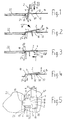
- the locking element 2 has protruding downwards from each other away to the front or to the rear facing plug-in surfaces or catch surfaces 6 and 8 for inserting or latching the locking element 2 in the locking position 3 and 5 between the front and rear transverse surfaces 10 and 12, which are formed next to or in a slot 16 of a first component 14.
- the rear transverse surface 12 is the rear Transverse edge of the slot 16; and the front transverse surface 10 is through end faces an edge shoulder 24 of the first component 14 on both sides next to the front End of the slot 16 formed.
- a locking part 18 is a tongue-like extension of the base body 4 with preferably the same thickness and width as the base body.
- the locking part 18 extends over the front plug or detent surface 6 by a distance 20 forward, which is at least as long as the locking distance, by which the locking element 2 of that shown in Figures 2 and 4 3 must be moved to the unlocked position overlap the edge of a second component 22 and thereby in a margin 24 to hold the first component 14.
- the base body 4 has two opposite one another on a front section laterally projecting lower gripping wings 26 and 28 for reaching under each other opposite longitudinal edges 30 of a front slot section 32, which is narrower on both sides than a rear slot section 34 of the Slot 16, which can be seen in particular from Figures 1 and 5.
- the longitudinal edges of the wider rear slot section 34 are denoted by 36.
- the lower gripping wings 26 and 28 form at their angled outer wing ends each on the front Front end a forward facing plug or catch surface 6 and extend from there backwards to about half the length of the locking element.
- the base body 4 has two at a rear section opposite to each other overlapping wings 38 and 40 projecting laterally for overlapping the longitudinal edges 36 of the wider rear slot portion 34 and the rear transverse edge 12 of the Slot 16.
- the overlap wings 38 and 40 have a short distance in the longitudinal direction of the slot from the undergrip wings 26 and 28 and extend rearward to the plug-in or, stretching downwards below them, pointing backwards Detent surface 8 of the base body 4.
- the rear overlap wings 38 and 40 are with respect to the front overlap wings 26 and 28 in the longitudinal direction of the slot 16 and relative to each other around the Thickness 44 of the first component 14 is offset in height from one another, so that the lower surface of the overlap wings 38 and 40 from the upper surface of the Under-gripping wing 26, 28 has a height distance which is equal to the thickness 44 of the first Component 14 is.
- the base body 4 lies in the locked locking position 3 in a plane parallel to the levels of the two components 14 and 22.
- the surface of the base body 4 and the overlapping wings 38 and 40 are completely flat or flat and lie in the same plane.
- the lower gripping wings 26 and 28 are opposite to the plane of the base body 4 formed at the bottom and outwards and have ends at the ends protruding ribs 46, the highest point 48 of which is the area which the front Longitudinal edges 30 of the slot 16 laterally engages and on the underside of the first Component 14 abuts when the component is in the locked position.
- the span of the lower gripping wings 26 and 28 is smaller than the span of the Overlap wings 38 and 40 and also slightly smaller than the width of the rear slot section 34. This allows the locking element with its lower gripping wings 26 and 28 ahead through the wider rear slot portion 34 of slot 16 1, and then pushed forward according to FIG. 2 and can be folded down to the under gripping wings 26 and 28 under the front Slide longitudinal edges 30 of the slot 16.
- the outer ribs 46 of the lower gripping wings 26 and 28 have from or near at its front end, the highest rib point 48 is a decreasing towards the rear Height around the insertion and tilting of the component according to FIGS. 1 and 2 to facilitate.
- a hook or catch arm 50 protrudes from the rear section of the base body 4 below and then at a vertical distance from the base body 4 to the rear so that its free end 52 points to the rear and between the part of the Catch arm 50 and the underside of the base body 4 a space open to the rear 54 is formed, which is below the rear plug or detent surface 8 lies.
- the rear arm end 52 is opposite the rear plug-in or detent surface 8 arranged lower and set back by a distance 56, which is shorter as the locking section 20.
- the task of the tentacle 50 is to fall out to prevent the locking element upwards.
- the Extend tentacle 50 as far back as possible.
- This extension after rear is limited, however, by the fact that the rear end 52 of the arm when inserted in the slot 16 in the unlocked position on the rear transverse edge 12 of the slot 16 has to be moved past in order to move from the position shown in FIG Fig. 3 position to arrive.
- the locking position the locking element through its plug connection with the edges or side surfaces of slot 16 held in place.
- the hook or catch arm 50 causes the locking element to fall out.
- an operating handle 60 which has the shape of a plate extending transversely to the base body and consists of one piece with the basic body.
- the operating handle can be on any Place be arranged, but preferably according to the drawings within the rear end area of the lower gripping wings 26 and 28, midway between them.
- the actuating handle 60 can be on the side facing away from it be arranged on the upper side of the base body 4, which is provided by the Purpose of the locking element is dependent.
- the locking element can be arranged in any horizontal, vertical or inclined position or vice versa (upside down) without it becoming inoperative or falling out of the slot in the locking position or in the unlocking position. That is why the terms used here are top, bottom, front, back “are only to be understood as examples and are only used for ease of illustration, without restricting the scope of protection, but are also to be understood in reverse, so that below “too above “and vice versa and front "and behind "can be reversed.
Landscapes
- Engineering & Computer Science (AREA)
- Mechanical Engineering (AREA)
- Details Of Connecting Devices For Male And Female Coupling (AREA)
- Connection Of Plates (AREA)
- Clamps And Clips (AREA)
- Buckles (AREA)
Abstract
Description
- Fig. 1
- einen vertikalen Längsschnitt durch ein Verriegelungselement nach der Erfindung in schräger Lage beim Einsetzen in einen T-förmigen Schlitz eines ersten Bauelements,
- Fig. 2
- das Verriegelungselement von Fig. 1 beim Umklappen auf das erste Bauelement,
- Fig. 3
- das Bauelement nach den Fig. 1 und 2 nach dem Verrasten (Einstecken oder Einschnappen) in den Schlitz in der Verriegelungsstellung,
- Fig. 4
- das Verriegelungselement von Fig. 1, nachdem es von er Position von Fig. 3 entrastet und in Entriegelungsstellung bewegt wurde, wobei ein Fangarm einen hinteren Querrand des Schlitzes untergreift und dadurch ein Herausfallen des Verriegelungselements verhindert,
- Fig. 5
- eine Draufsicht auf das Verriegelungselement in Verriegelungsstellung mit beiden Bauelementen,
- Fig. 6
- das Verriegelungselement in vergrößerter Draufsicht ohne die zu verriegelnden Bauelemente,
- Fig. 7
- eine Seitenansicht des Verriegelungselements von Fig. 6,
- Fig. 8
- einen Längsschnitt längs der Ebene VIII-VIII von Fig. 6 und
- Fig. 9
- einen Querschnitt längs der Ebene IX-IX von Fig. 6.

Claims (9)
- Verriegelungselement, welches in einem Schlitz (16) eines ersten Bauelements (14) zwischen einer Verriegelungsstellung und einer Endriegelunsstellung in Schlitzlängsrichtung verstellbar ist, um einen Verriegelungsteil (18) des Verriegelungselements in einen zu sperrenden Bewegungsweg, bzw. aus diesem heraus, eines zweiten Bauelements (22) zu bewegen, dadurch gekennzeichnet, daß das Verriegelungselement (2) mit Steckerflächen (6, 8) oder Rastenflächen zum Stecken oder Einrasten zwischen Gegenflächen des ersten Bauelements (14) in oder neben dem Schlitz in Richtung senkrecht zur Schlitzöffnung in Verriegelungsstellung ausgebildet ist.
- Verriegelungselement nach Anspruch 1, dadurch gekennzeichnet, daß es auf seiner Unterseite einen Fangarm (50) aufweist, welcher gegenüber den Stecker- oder Rastenflächen (6, 8) um eine Strecke (56) zurückgesetzt ist, welche ein Einsetzen des Verriegelungselementes (16) in den Schlitz (16) und den Steckvorgang in der Verriegelungsstellung ermöglicht, jedoch kürzer ist als die Verriegelungsstrecke von der Verriegelungsstellung zur Entriegelungsstellung, so daß der Fangarm (50) in und nahe bei der Entriegelungsstellung einen hinteren Querrand (12) des Schlitzes (16) untergreift und dabei ein Herausfallen des Verriegelungselements aus dem Schlitz verhindert.
- Verriegelungselement nach Anspruch 1 oder 2, dadurch gekennzeichnet, daß es einen Grundkörper (4) aufweist, daß der Grundkörper (4) auf seinem vorderen Abschnitt zwei entgegengesetzt voneinander seitlich wegragende Untergreif-Flügel (26, 28) zum Untergreifen der beiden seitlichen Längsränder (30) des Schlitzes (16) hat, und daß der Grundkörper (4) auf einem hinteren Abschnitt zwei entgegengesetzt voneinander seitlich wegragende Übergreif-Flügel (38,40) zum Übergreifen der beidseitigen Längsränder (36) des Schlitzes (16) hat, wobei die Übergreif-Flügel (38, 40) relativ zu den Üntergreif-Flügeln (26, 28) in Schlitzlängsrichtung versetzt zueinander angeordnet sind und die als Stützflächen dienenden unteren Oberflächen der Übergreif-Flügel (38, 40) und oberen Oberflächen der Untergreif-Flügel (26, 28) um die Höhe der Schlitzränder (30, 36, 12) höhenversetzt zueinander angeordnet sind und in eingestecktem Zustand des Verriegelungselements an der Unterseite bzw. an der Oberseite des ersten Bauelements (14) anliegen.
- Verriegelungselement nach einem der Ansprüche 1 bis 3, dadurch gekennzeichnet, daß die Steck- oder Rastenflächen (6, 8) voneinander weg nach vorne und nach hinten zeigende Flächen sind zum Einstecken oder Einrasten zwischen vorderen und hinteren Querrandbereichen (10, 12) des Schlitzes (16) in Verriegelungsstellung.
- Verriegelungselement nach Anspruch 3 oder 4, dadurch gekennzeichnet, daß die Übergreif-Flügel (38, 40) eine größere Spannweite als die Untergreif-Flügel (26, 28) haben zur Überdeckung eines gegenüber einem vorderen Abschnitt (32) beidseitig breiteren hinteren Abschnitt (34) des Schlitzes (16), und daß die Untergreif-Flügel (26, 28) eine Spannweite haben, welche wenig kleiner ist als die Breite des hinteren Schlitzabschnittes (34).
- Verriegelungselement nach einem der vorhergehenden Ansprüche, dadurch gekennzeichnet, daß es einen Betätigungsgriff (60) aufweist.
- Betätigungselement nach Anspruch 6, dadurch gekennzeichnet, daß der Betätigungsgriff (60) sich auf der dem Schlitz zugewandten Unterseite des Verriegelungselements befindet.
- Verriegelungselement nach einem der vorhergehenden Ansprüche, dadurch gekennzeichnet, daß es eine plattenartig dünne Grundform hat.
- Verriegelungselement nach einem der vorhergehenden Ansprüche, dadurch gekennzeichnet, daß alle seine Teile einstückig aus einem einzigen Materialkörper bestehen.
Applications Claiming Priority (2)
| Application Number | Priority Date | Filing Date | Title |
|---|---|---|---|
| DE29809745U DE29809745U1 (de) | 1998-05-29 | 1998-05-29 | Verriegelungselement |
| DE29809745U | 1998-05-29 |
Publications (2)
| Publication Number | Publication Date |
|---|---|
| EP0962613A2 true EP0962613A2 (de) | 1999-12-08 |
| EP0962613A3 EP0962613A3 (de) | 2002-11-20 |
Family
ID=8057899
Family Applications (1)
| Application Number | Title | Priority Date | Filing Date |
|---|---|---|---|
| EP99110415A Withdrawn EP0962613A3 (de) | 1998-05-29 | 1999-05-28 | Verriegelungselement |
Country Status (2)
| Country | Link |
|---|---|
| EP (1) | EP0962613A3 (de) |
| DE (1) | DE29809745U1 (de) |
Families Citing this family (2)
| Publication number | Priority date | Publication date | Assignee | Title |
|---|---|---|---|---|
| DE102008017286A1 (de) * | 2008-04-04 | 2009-10-08 | BSH Bosch und Siemens Hausgeräte GmbH | Dunstabzugsvorrichtung |
| DE102010003901A1 (de) * | 2010-04-13 | 2011-10-13 | BSH Bosch und Siemens Hausgeräte GmbH | Aufhängsicherung für Essen und Hauben |
Family Cites Families (4)
| Publication number | Priority date | Publication date | Assignee | Title |
|---|---|---|---|---|
| US3850464A (en) * | 1973-05-23 | 1974-11-26 | R Bisbing | Slam-latch |
| US4790579A (en) * | 1988-03-01 | 1988-12-13 | Siemens Energy & Automation, Inc. | Sliding spring latch |
| US5121952A (en) * | 1988-07-20 | 1992-06-16 | Elastolatch, Inc. | Slam latch |
| US5231948A (en) * | 1992-06-30 | 1993-08-03 | Tempress, Inc. | Hatch with improved latch and hinge assembly |
-
1998
- 1998-05-29 DE DE29809745U patent/DE29809745U1/de not_active Expired - Lifetime
-
1999
- 1999-05-28 EP EP99110415A patent/EP0962613A3/de not_active Withdrawn
Non-Patent Citations (1)
| Title |
|---|
| None |
Also Published As
| Publication number | Publication date |
|---|---|
| DE29809745U1 (de) | 1999-09-30 |
| EP0962613A3 (de) | 2002-11-20 |
Similar Documents
| Publication | Publication Date | Title |
|---|---|---|
| DE69722836T2 (de) | Kunststoffmodul für eine Fördermatte | |
| DE2633972A1 (de) | Verbindungsanordnung fuer moebel | |
| DE2446080C2 (de) | Trennwandsystem mit einem ersten und einem zweiten Trennwandelement und einem Verbindungsteil | |
| DE3311219A1 (de) | Vorrichtung zum verbinden eines wischerarmes mit einem wischerblatt | |
| DE3119176C2 (de) | Vorrichtung zum Verbinden eines Windschutzscheibenwischerarms mit einem Windschutzscheiben-Wischerblatt | |
| DE9411165U1 (de) | Spreizanker | |
| DE102010061554B4 (de) | Abdeckvorrichtung für eine Entwässerungsmulde | |
| DE19710515C1 (de) | Steckkarte für elektronische Geräte | |
| DE102008034775A1 (de) | Vorrichtung zum Verbinden zweier Schränke für Schaltgeräte | |
| CH661962A5 (de) | Eckumlenkung eines in hinterschnittene profilnuten der rahmenprofile von fenstern und tueren einsetzbaren treibstangenverschlusses. | |
| DE3616031A1 (de) | Steckverbindung und informationstafel mit steckverbindung | |
| EP0630439B1 (de) | Stangenverriegelung für insbesondere schaltschranktüren | |
| EP0962613A2 (de) | Verriegelungselement | |
| DE2604267A1 (de) | Einstellbare arretiereinrichtung | |
| DE4410724A1 (de) | Rollzwischenelement für ein Antriebsgelenk | |
| DE2656397A1 (de) | Selbstsperrender schieber fuer reissverschluesse | |
| EP4166039A1 (de) | Schubladenseitenwand | |
| DE3343775C2 (de) | Eckumlenkung | |
| DE19742095C1 (de) | Anordnung zur schraubenlosen Verbindung von Gitterkabelbahnen | |
| CH687716A5 (de) | Beschlag. | |
| EP0947652B1 (de) | Überlappungsverbindung, insbesondere für die Stulpschiene eines Treibstangenbeschlags | |
| DE3221926C2 (de) | Auszieheinrichtung für einen mit einem Möbelkorpus versehenen Schrank | |
| DE19611808C2 (de) | Ortgangverkleidung | |
| DE9016592U1 (de) | Geradverbinder, insbesondere aus Kunststoff, zur Verbindung von hohlen Abstandsprofilen und hohlen Sprossenprofilen eines Mehrscheibenisolierglases | |
| DE20000627U1 (de) | Vorrichtung zur axialfesten Fixierung von Gegenständen in einer hinterschnittenen Nut |
Legal Events
| Date | Code | Title | Description |
|---|---|---|---|
| PUAI | Public reference made under article 153(3) epc to a published international application that has entered the european phase |
Free format text: ORIGINAL CODE: 0009012 |
|
| AK | Designated contracting states |
Kind code of ref document: A2 Designated state(s): AT BE CH CY DE DK ES FI FR GB GR IE IT LI LU MC NL PT SE |
|
| AX | Request for extension of the european patent |
Free format text: AL;LT;LV;MK;RO;SI |
|
| PUAL | Search report despatched |
Free format text: ORIGINAL CODE: 0009013 |
|
| AK | Designated contracting states |
Kind code of ref document: A3 Designated state(s): AT BE CH CY DE DK ES FI FR GB GR IE IT LI LU MC NL PT SE |
|
| AX | Request for extension of the european patent |
Free format text: AL;LT;LV;MK;RO;SI |
|
| RIC1 | Information provided on ipc code assigned before grant |
Free format text: 7E 05C 1/02 A, 7A 47B 96/00 B, 7A 47G 1/06 B, 7F 24F 7/00 B, 7F 24B 15/00 B, 7E 05C 1/04 B |
|
| 17P | Request for examination filed |
Effective date: 20030520 |
|
| AKX | Designation fees paid |
Designated state(s): DE ES FR GB IT SE |
|
| 17Q | First examination report despatched |
Effective date: 20030821 |
|
| RAP1 | Party data changed (applicant data changed or rights of an application transferred) |
Owner name: BSH BOSCH UND SIEMENS HAUSGERAETE GMBH |
|
| GRAP | Despatch of communication of intention to grant a patent |
Free format text: ORIGINAL CODE: EPIDOSNIGR1 |
|
| STAA | Information on the status of an ep patent application or granted ep patent |
Free format text: STATUS: THE APPLICATION IS DEEMED TO BE WITHDRAWN |
|
| 18D | Application deemed to be withdrawn |
Effective date: 20111011 |