EP0962705A2 - Gaskochstelle mit Tragrahmen - Google Patents
Gaskochstelle mit Tragrahmen Download PDFInfo
- Publication number
- EP0962705A2 EP0962705A2 EP99110367A EP99110367A EP0962705A2 EP 0962705 A2 EP0962705 A2 EP 0962705A2 EP 99110367 A EP99110367 A EP 99110367A EP 99110367 A EP99110367 A EP 99110367A EP 0962705 A2 EP0962705 A2 EP 0962705A2
- Authority
- EP
- European Patent Office
- Prior art keywords
- display
- support frame
- gas
- gas hob
- hob according
- Prior art date
- Legal status (The legal status is an assumption and is not a legal conclusion. Google has not performed a legal analysis and makes no representation as to the accuracy of the status listed.)
- Granted
Links
- 239000002184 metal Substances 0.000 claims abstract description 9
- 239000003086 colorant Substances 0.000 claims description 3
- 230000008878 coupling Effects 0.000 claims description 2
- 238000010168 coupling process Methods 0.000 claims description 2
- 238000005859 coupling reaction Methods 0.000 claims description 2
- 238000010411 cooking Methods 0.000 abstract description 9
- 239000002241 glass-ceramic Substances 0.000 description 7
- 238000004140 cleaning Methods 0.000 description 3
- 230000001419 dependent effect Effects 0.000 description 2
- 238000011161 development Methods 0.000 description 2
- 230000018109 developmental process Effects 0.000 description 2
- 229910000639 Spring steel Inorganic materials 0.000 description 1
- 229910000831 Steel Inorganic materials 0.000 description 1
- 230000005540 biological transmission Effects 0.000 description 1
- 238000006243 chemical reaction Methods 0.000 description 1
- 238000001514 detection method Methods 0.000 description 1
- 230000003670 easy-to-clean Effects 0.000 description 1
- 238000011156 evaluation Methods 0.000 description 1
- 238000010438 heat treatment Methods 0.000 description 1
- 239000004973 liquid crystal related substance Substances 0.000 description 1
- 230000003287 optical effect Effects 0.000 description 1
- 239000003223 protective agent Substances 0.000 description 1
- 230000002441 reversible effect Effects 0.000 description 1
- 230000000630 rising effect Effects 0.000 description 1
- 230000011664 signaling Effects 0.000 description 1
- 229910001220 stainless steel Inorganic materials 0.000 description 1
- 239000010935 stainless steel Substances 0.000 description 1
- 239000010959 steel Substances 0.000 description 1
- 239000000126 substance Substances 0.000 description 1
- 238000012549 training Methods 0.000 description 1
- XLYOFNOQVPJJNP-UHFFFAOYSA-N water Substances O XLYOFNOQVPJJNP-UHFFFAOYSA-N 0.000 description 1
Images
Classifications
-
- F—MECHANICAL ENGINEERING; LIGHTING; HEATING; WEAPONS; BLASTING
- F24—HEATING; RANGES; VENTILATING
- F24C—DOMESTIC STOVES OR RANGES ; DETAILS OF DOMESTIC STOVES OR RANGES, OF GENERAL APPLICATION
- F24C3/00—Stoves or ranges for gaseous fuels
- F24C3/12—Arrangement or mounting of control or safety devices
- F24C3/126—Arrangement or mounting of control or safety devices on ranges
Definitions
- the invention relates to a gas hob with at least one gas burner, a trough base plate and a support frame for cookware.
- pan supports so that pots, Pans or similar do not rest directly on the gas burner.
- the pan supports are often used as a glass ceramic plate or removable support frame.
- the support frame usually exists made of enamelled steel.
- Such support frames heat up both during cooking by the radiant heat of the gas flame as well as by the heat conduction within the Frame strong.
- the support frame must, however, especially for cleaning the underlying Trough base plate can be removed frequently.
- DE 25 45 239 A1 discloses a residual heat indicator in which one that is already present in the stove Display activated when the predetermined temperature of a cooking zone is exceeded is that there is a warning of residual heat on the display.
- DE 91 01 823 U1 discloses a device made of plastic for displaying the residual heat, in which a lamp bulb is arranged in specially designed receiving sleeves. But here too the device for displaying residual heat is located underneath a glass ceramic plate, so that the electrical supply is easy to implement there, but not for the Use in or on a support frame is suitable.
- gas hobs have no residual or post-heat indicator or gas hobs in combination with glass ceramic plates, there are residual or residual heat indicators always dependent on an electrical power supply.
- the electrical ones Lines arranged below a glass ceramic plate.
- the invention thus poses the problem of gas cooktops with support frames for Design cookware in such a way that a warning of excessive temperatures on the support frame done with little effort.
- the advantages achievable with the invention are achieved by integrating at least one warning Display device for residual heat reached in a support frame.
- the display device for residual heat gives the user a long time after the gas burner is switched off optimal safety, because it is a direct thermal coupling with the support frame Risk of burns signaled.
- a particular advantage is immediate and reliable warning of high temperatures of the support frame, without use an electric light or electronic temperature sensors.
- the display device to avoid misinformation at a location of the Support frame arranged, which is not exposed to the direct radiant heat of the gas burner is.
- the display device for residual or residual heat works mechanically and is without an electrical power supply is functional.
- the bi- or memory metal strip is made of spring steel, for example, to prevent movement of the display segments depending on the temperature.
- the Display area should be in an open area (visible to the operator) and a hidden area (invisible) area. It is particularly advantageous if this is alarming Display segment only visible at temperatures> 60 ° C and when it drops below this temperature value is invisible again. The user receives when this display segment appears the quick information that the support frame is too hot to touch without protection is.
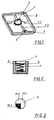
- FIG. 1 shows a single hotplate with a gas burner (2), one the gas burner (2) surrounded bowl base plate (8) and a support frame (1) for putting on cookware above the gas burner (2).
- Such trough base plates (8) usually have one Surface that is enamelled or made of stainless steel.
- a display device (3) for subsequent or Residual heat is integrated directly into the support frame (1).
- the display device (3) is a Contain means (5) which has a direct thermal connection to the support frame (1).
- the display device (3) works reliably mechanically without electrical Power supply.
- a display device (3) in the Support frame (1) is arranged, which after a direct detection of the temperature on Support frame (1) an evaluation and conversion of the measured value into an electrical Carries out signal and a transmission of the signal to an electronic display device (3) makes.
- this requires a power supply, which is also in the support frame (1) is to be integrated.
- the support frame (1) consists of an outer frame area (1.1) and several, with this connected and radiating to the gas burner (2) facing support webs (1.2).
- the display element (3) In order to provide a meaningful signaling of the temperature for the largest possible To be able to make area of the support frame (1) is the display element (3) for Depending on the temperature resistance, residual heat is arranged in an area which is not the is directly exposed to radiant heat from the gas burner (2). This is the optimal arrangement Display element (3) is therefore arranged in the outer frame area (1.1), at the intersection with a footbridge (1.2). For this purpose, the outer frame area (1.1) has a recess (4) Recording the display element (3). With large support frames, which have several gas burners (2) are arranged, it is quite possible to have several display elements (3) different places. This increases the accuracy of the warning for individual sections of the support frame (1). For example, if only one gas burner (2) in Is or was in operation, the support frame (1) may be touched at another end, without having to take any special precautions.
- FIG. 2 shows a section through a simple structure of a display element (3).
- the Display element (3) consists of several individual parts. In particular, are a metal strip (5), a movable display surface (6) connected to it and one the display surface (6) covering transparent cover plate (7) necessary components. These components (5, 6, 7) are individually inserted in a recess (4) of the support frame (1) and then connected to the support frame (1) in a watertight manner. It is even more advantageous if the display element (3) represents a complete assembly with all its components (5, 6, 7), which is arranged in its own housing (9). Such a component (3) becomes detachable or permanently inserted into the recess (4) of the support frame (1).
- the metal strip (5) is preferably made from a bi- or memory metal spring. Thereby becomes the temperature-dependent movement of display segments (10.1 -10.n) of the display surface (6) performed exactly. Due to the increasing temperature on the support frame (1) the metal strip (5) extends and moves the display segments (10.1-10.n) of the display surface (6). These can either move in a circular or a linear path. The correct information quickly reaches the cooktop user without a connection to the electrical power grid must be available.
- the display segments (10.1 -10.n) should be characterized by different color and / or pattern areas, each Each segment (10.1, 10.2, - 10.n) is assigned a temperature or a temperature range is.
- the display segment (10.1) which belongs to temperatures> 60 ° C, should be special be conspicuous because a direct contact with the support frame (1) from these temperatures direct risk of burns.
- the cover plate (7) which is transparent in at least one partial area, serves the purpose Protection of the display element (3) against external mechanical and chemical stresses. It is connected to the display element (3) such that this in the upper Area of the support frame (1) or its own housing is watertight. This prevents soiling that leads to disruptions in the display can get into the interior of the display element (3). To the warning of the too high Clearly recognizing the temperatures of the support frame (1) is a design of the cover plate (7) useful as a lens. This makes an optical magnification of the otherwise relative small warning display area (6) created.
- the cooking frame (1) is often dirty during cooking in addition to the trough base plate (8), it is advantageous if the latter, together with the display element (3), is dishwasher-safe Unity. This means that it can be removed without much effort after removal be cleaned thoroughly. However, it must then be ensured that nowhere Water can penetrate into the display element (3). But it is also possible to use the display element (3) to be designed as a separate component and to be arranged in a watertight housing (9). The housing (9) is watertightly connected to the transparent cover plate (7). In In such an embodiment, it can be removed from the supporting frame (1). Support frame (1) and display element (3) must then be cleaned separately if necessary.
- a display surface (6) is shown in plan view in FIG. It has a visible segment in which the display segment (10.1) appears when the temperature is too high. This visible segment takes up about a quarter of the total display area (6) in this example. The rest of the area is invisible from above. Of course, there are other subdivisions realizable. Due to the moving display segments (10.1-10.n) appears always a different display segment in the visible segment. Only at temperatures> 60 ° C the display segment (10.1) appears and signals an immediate danger when touched the support frame (1). It is therefore important for the user that the display area (6) Temperatures> 60 ° C contain a particularly striking warning.
- the display area (6) is in no way on the proposed shape tied to the segments. It is any other configuration For example, a reversible liquid crystal display can also be used.
Landscapes
- Engineering & Computer Science (AREA)
- Chemical & Material Sciences (AREA)
- Combustion & Propulsion (AREA)
- Mechanical Engineering (AREA)
- General Engineering & Computer Science (AREA)
- Cookers (AREA)
- Electric Stoves And Ranges (AREA)
Abstract
Description
- Figur 1
- Tragrahmen für eine Einzelkochstelle mit einem Gasbrenner und einem Anzeigeelement für Nachwärme
- Figur 2
- Ausgestaltung eines Anzeigeelementes im Schnitt
- Figur 3
- Anzeigeelement in Draufsicht
Claims (10)
- Gaskochstelle mit mindestens einem Gasbrenner, einer Muldengrundplatte und einem Tragrahmen für Kochgeschirr,
dadurch gekennzeichnet,daß im Tragrahmen (1) mindestens eine Anzeigeeinrichtung (3) für Restwärme integriert ist, wobei die Anzeigeeinrichtung (3) wenigstens ein in thermischer Koppelung mit dem Tragrahmen (1) stehendes Mittel (5) aufweist. - Gaskochstelle nach Anspruch 1,
dadurch gekennzeichnet,daß das Mittel (5) als Bi- oder Memorymetallstreifen ausgebildet ist und mit einer Anzeigefläche (6) verbunden ist. - Gaskochstelle nach Anspruch 1 oder 2,
dadurch gekennzeichnet,daß die Anzeigeeinrichtung (3) an einer Stelle des Tragrahmens (1) angeordnet ist, welche nicht direkter Strahlungswärme des Gasbrenners (2) ausgesetzt ist. - Gaskochstelle nach mindestens einem der Ansprüche 1 bis 3,
dadurch gekennzeichnet,daß die Anzeigeeinrichtung (3) keine Verbindung zu einer elektrischen Stromversorgung aufweist. - Gaskochstelle nach mindestens einem der Ansprüche 1 bis 4,
dadurch gekennzeichnet,daß oberhalb der Anzeigefläche (6) eine temperaturbeständige, durchsichtige Abdeckplatte (7) angeordnet ist. - Gaskochstelle nach Anspruch 5,
dadurch gekennzeichnet,daß die Abdeckplatte (7) als vergrößernde Linse ausgebildet ist. - Gaskochstelle nach mindestens einem der Ansprüche 1 bis 6,
dadurch gekennzeichnet,daß der Metallstreifen (5) als Feder ausgebildet ist, welche mit Anzeigesegmenten (10.1 - 10.n) verbunden ist, wobei jedes Anzeigesegmente (10.1 -10.n) an der Anzeigefläche (6) unterschiedlichen Temperaturen zugeordnet ist. - Gaskochstelle nach Anspruch 1 bis 7,
dadurch gekennzeichnet,daß mindestens ein Anzeigesegment (10.1) den Temperaturen > 60°C zugeordnet ist und auf der Anzeigefläche (6) einen heißen Tragrahmen signalisiert. - Gaskochstelle nach mindestens einem der Ansprüche 1 bis 8,
dadurch gekennzeichnet,daß das Anzeigesegment (10.1) beweglich ausgebildet ist und erst bei Temperaturen > 60°C auf der Anzeigefläche (6) sichtbar ist. - Gaskochstelle nach mindestens einem der Ansprüche 1 bis 9,
dadurch gekennzeichnet,daß die Anzeigesegmente (10.1 -10.n) für unterschiedliche Temperaturen andersfarbig ausgebildet sind.
Applications Claiming Priority (2)
| Application Number | Priority Date | Filing Date | Title |
|---|---|---|---|
| DE19825140A DE19825140A1 (de) | 1998-06-05 | 1998-06-05 | Gaskochstelle mit Tragrahmen |
| DE19825140 | 1998-06-05 |
Publications (3)
| Publication Number | Publication Date |
|---|---|
| EP0962705A2 true EP0962705A2 (de) | 1999-12-08 |
| EP0962705A3 EP0962705A3 (de) | 2000-06-07 |
| EP0962705B1 EP0962705B1 (de) | 2003-11-19 |
Family
ID=7870007
Family Applications (1)
| Application Number | Title | Priority Date | Filing Date |
|---|---|---|---|
| EP99110367A Expired - Lifetime EP0962705B1 (de) | 1998-06-05 | 1999-05-28 | Gaskochstelle mit Tragrahmen |
Country Status (4)
| Country | Link |
|---|---|
| EP (1) | EP0962705B1 (de) |
| DE (2) | DE19825140A1 (de) |
| ES (1) | ES2210896T3 (de) |
| PT (1) | PT962705E (de) |
Families Citing this family (1)
| Publication number | Priority date | Publication date | Assignee | Title |
|---|---|---|---|---|
| DE102009024236A1 (de) * | 2009-05-28 | 2010-12-02 | E.G.O. Elektro-Gerätebau GmbH | Gas-Kochfeld mit einer Kochfeldplatte und mindestens einer Kochstelle |
Citations (3)
| Publication number | Priority date | Publication date | Assignee | Title |
|---|---|---|---|---|
| DE2545239A1 (de) | 1975-10-09 | 1977-04-21 | Bbc Brown Boveri & Cie | Elektronischer temperaturregler fuer heizelemente |
| DE3800860A1 (de) | 1987-02-13 | 1988-08-25 | Pistor & Boss Gmbh | Restwaermeanzeigevorrichtung |
| DE9101823U1 (de) | 1991-02-17 | 1991-05-29 | Pistor + Boss GmbH, 5880 Lüdenscheid | Vorrichtung aus Kunststoff zur Anzeige der Restwärme von Kochplatten |
Family Cites Families (3)
| Publication number | Priority date | Publication date | Assignee | Title |
|---|---|---|---|---|
| US3186472A (en) * | 1962-10-22 | 1965-06-01 | Frank S Caravella | Signal system |
| DE29619581U1 (de) * | 1996-11-13 | 1997-03-13 | Schott Glaswerke, 55122 Mainz | Glaskeramikkochfeld mit sensorgesteuerten Anzeigeeinrichtungen für offene, atmosphärische Gasbrenner als Brennstellen umfassende Kochzonen |
| IT1296492B1 (it) * | 1997-11-21 | 1999-06-25 | Whirlpool Co | Sistema per indicare il calore residuo delle griglie di apparecchi domestici di cottura a gas |
-
1998
- 1998-06-05 DE DE19825140A patent/DE19825140A1/de not_active Withdrawn
-
1999
- 1999-05-28 PT PT99110367T patent/PT962705E/pt unknown
- 1999-05-28 ES ES99110367T patent/ES2210896T3/es not_active Expired - Lifetime
- 1999-05-28 DE DE59907767T patent/DE59907767D1/de not_active Expired - Fee Related
- 1999-05-28 EP EP99110367A patent/EP0962705B1/de not_active Expired - Lifetime
Patent Citations (3)
| Publication number | Priority date | Publication date | Assignee | Title |
|---|---|---|---|---|
| DE2545239A1 (de) | 1975-10-09 | 1977-04-21 | Bbc Brown Boveri & Cie | Elektronischer temperaturregler fuer heizelemente |
| DE3800860A1 (de) | 1987-02-13 | 1988-08-25 | Pistor & Boss Gmbh | Restwaermeanzeigevorrichtung |
| DE9101823U1 (de) | 1991-02-17 | 1991-05-29 | Pistor + Boss GmbH, 5880 Lüdenscheid | Vorrichtung aus Kunststoff zur Anzeige der Restwärme von Kochplatten |
Also Published As
| Publication number | Publication date |
|---|---|
| EP0962705B1 (de) | 2003-11-19 |
| DE19825140A1 (de) | 1999-12-09 |
| DE59907767D1 (de) | 2003-12-24 |
| PT962705E (pt) | 2004-04-30 |
| EP0962705A3 (de) | 2000-06-07 |
| ES2210896T3 (es) | 2004-07-01 |
Similar Documents
| Publication | Publication Date | Title |
|---|---|---|
| DE3879189T2 (de) | Bedienungseinrichtung fuer elektrische kochherde. | |
| EP1858299B1 (de) | Verwendung von linkshändigen Metamaterialien als Anzeige, insbesondere an einem Kochfeld, und Anzeige sowie Anzeigeverfahren | |
| DE60303573T2 (de) | Kochvorrichtung | |
| EP0110062B1 (de) | Einrichtung an einem Kochgefäss insbesondere Dampfdruckkochtopf | |
| EP0690659B1 (de) | Infrarotgesteuerte Garungseinheit | |
| EP0388727A2 (de) | Schaltgerät für einen Kochherd | |
| EP2024686B1 (de) | Hausgerät, vorzugsweise kochfeld | |
| DE10312449A1 (de) | Herdplattenanzeigeeinsatz | |
| EP2256417A2 (de) | Gas-Kochfeld mit einer Kochfeldplatte und mindestens einer Kochstelle | |
| DE19825321C1 (de) | Kochfeld mit Bedieneinheit zur Vorgabe der Leistungsstufe und Verfahren zum Einstellen der Leistungsstufe eines Heizelementes eines Kochfeldes | |
| DE2627373A1 (de) | Signaleinrichtung an kochgeraeten mit einer glaskeramikkochflaeche | |
| DE69814000T2 (de) | Anzeigevorrichtung für die Restwärme von Topfträger bei Haushaltgaskochern | |
| DE3117205A1 (de) | Optoelektronische kochfeldsteuerung | |
| DE3433880A1 (de) | Kochmulde | |
| DE29706787U1 (de) | Kochfeld mit kennzeichnender Beleuchtung der Kochstelle | |
| EP0962705B1 (de) | Gaskochstelle mit Tragrahmen | |
| DE4105627C2 (de) | ||
| DE3209260A1 (de) | Kochfeld aus glaskermaischem material | |
| DE2739760A1 (de) | Kochgeraet mit mehreren elektrokochplatten | |
| DE19514261A1 (de) | Herdmulde | |
| GB2368634A (en) | Cook top status indicator | |
| WO1996014010A1 (de) | Kochbehälter | |
| EP0921708A1 (de) | Induktionskochgerät für ein Kochgefäss aus ferromagnetischem Material | |
| DE102011087217A1 (de) | Bedieneinrichtung für ein Elektrogerät | |
| DE4233470A1 (de) | Kochmulde |
Legal Events
| Date | Code | Title | Description |
|---|---|---|---|
| PUAI | Public reference made under article 153(3) epc to a published international application that has entered the european phase |
Free format text: ORIGINAL CODE: 0009012 |
|
| AK | Designated contracting states |
Kind code of ref document: A2 Designated state(s): BE DE ES FR GB IT NL PT |
|
| AX | Request for extension of the european patent |
Free format text: AL;LT;LV;MK;RO;SI |
|
| PUAL | Search report despatched |
Free format text: ORIGINAL CODE: 0009013 |
|
| AK | Designated contracting states |
Kind code of ref document: A3 Designated state(s): AT BE CH CY DE DK ES FI FR GB GR IE IT LI LU MC NL PT SE |
|
| AX | Request for extension of the european patent |
Free format text: AL;LT;LV;MK;RO;SI |
|
| 17P | Request for examination filed |
Effective date: 20001010 |
|
| AKX | Designation fees paid |
Free format text: BE DE ES FR GB IT NL PT |
|
| 17Q | First examination report despatched |
Effective date: 20021021 |
|
| GRAH | Despatch of communication of intention to grant a patent |
Free format text: ORIGINAL CODE: EPIDOS IGRA |
|
| RAP1 | Party data changed (applicant data changed or rights of an application transferred) |
Owner name: MIELE & CIE. KG |
|
| GRAS | Grant fee paid |
Free format text: ORIGINAL CODE: EPIDOSNIGR3 |
|
| GRAA | (expected) grant |
Free format text: ORIGINAL CODE: 0009210 |
|
| AK | Designated contracting states |
Kind code of ref document: B1 Designated state(s): BE DE ES FR GB IT NL PT |
|
| REG | Reference to a national code |
Ref country code: GB Ref legal event code: FG4D Free format text: NOT ENGLISH |
|
| REF | Corresponds to: |
Ref document number: 59907767 Country of ref document: DE Date of ref document: 20031224 Kind code of ref document: P |
|
| GBT | Gb: translation of ep patent filed (gb section 77(6)(a)/1977) |
Effective date: 20040227 |
|
| REG | Reference to a national code |
Ref country code: PT Ref legal event code: SC4A Free format text: AVAILABILITY OF NATIONAL TRANSLATION Effective date: 20040218 |
|
| REG | Reference to a national code |
Ref country code: ES Ref legal event code: FG2A Ref document number: 2210896 Country of ref document: ES Kind code of ref document: T3 |
|
| ET | Fr: translation filed | ||
| PLBE | No opposition filed within time limit |
Free format text: ORIGINAL CODE: 0009261 |
|
| STAA | Information on the status of an ep patent application or granted ep patent |
Free format text: STATUS: NO OPPOSITION FILED WITHIN TIME LIMIT |
|
| 26N | No opposition filed |
Effective date: 20040820 |
|
| PGFP | Annual fee paid to national office [announced via postgrant information from national office to epo] |
Ref country code: DE Payment date: 20050711 Year of fee payment: 7 |
|
| PGFP | Annual fee paid to national office [announced via postgrant information from national office to epo] |
Ref country code: PT Payment date: 20060509 Year of fee payment: 8 |
|
| PGFP | Annual fee paid to national office [announced via postgrant information from national office to epo] |
Ref country code: NL Payment date: 20060518 Year of fee payment: 8 |
|
| PGFP | Annual fee paid to national office [announced via postgrant information from national office to epo] |
Ref country code: FR Payment date: 20060519 Year of fee payment: 8 |
|
| PGFP | Annual fee paid to national office [announced via postgrant information from national office to epo] |
Ref country code: BE Payment date: 20060523 Year of fee payment: 8 |
|
| PGFP | Annual fee paid to national office [announced via postgrant information from national office to epo] |
Ref country code: GB Payment date: 20060524 Year of fee payment: 8 |
|
| PGFP | Annual fee paid to national office [announced via postgrant information from national office to epo] |
Ref country code: ES Payment date: 20060526 Year of fee payment: 8 |
|
| PGFP | Annual fee paid to national office [announced via postgrant information from national office to epo] |
Ref country code: IT Payment date: 20060531 Year of fee payment: 8 |
|
| REG | Reference to a national code |
Ref country code: GB Ref legal event code: 746 Effective date: 20061019 |
|
| PG25 | Lapsed in a contracting state [announced via postgrant information from national office to epo] |
Ref country code: DE Free format text: LAPSE BECAUSE OF NON-PAYMENT OF DUE FEES Effective date: 20061201 |
|
| REG | Reference to a national code |
Ref country code: PT Ref legal event code: MM4A Free format text: LAPSE DUE TO NON-PAYMENT OF FEES Effective date: 20071128 |
|
| BERE | Be: lapsed |
Owner name: *MIELE & CIE. K.G. Effective date: 20070531 |
|
| GBPC | Gb: european patent ceased through non-payment of renewal fee |
Effective date: 20070528 |
|
| PG25 | Lapsed in a contracting state [announced via postgrant information from national office to epo] |
Ref country code: PT Free format text: LAPSE BECAUSE OF NON-PAYMENT OF DUE FEES Effective date: 20071128 Ref country code: NL Free format text: LAPSE BECAUSE OF NON-PAYMENT OF DUE FEES Effective date: 20071201 |
|
| NLV4 | Nl: lapsed or anulled due to non-payment of the annual fee |
Effective date: 20071201 |
|
| REG | Reference to a national code |
Ref country code: FR Ref legal event code: ST Effective date: 20080131 |
|
| PG25 | Lapsed in a contracting state [announced via postgrant information from national office to epo] |
Ref country code: BE Free format text: LAPSE BECAUSE OF NON-PAYMENT OF DUE FEES Effective date: 20070531 |
|
| PG25 | Lapsed in a contracting state [announced via postgrant information from national office to epo] |
Ref country code: GB Free format text: LAPSE BECAUSE OF NON-PAYMENT OF DUE FEES Effective date: 20070528 |
|
| PG25 | Lapsed in a contracting state [announced via postgrant information from national office to epo] |
Ref country code: FR Free format text: LAPSE BECAUSE OF NON-PAYMENT OF DUE FEES Effective date: 20070531 |
|
| REG | Reference to a national code |
Ref country code: ES Ref legal event code: FD2A Effective date: 20070529 |
|
| PG25 | Lapsed in a contracting state [announced via postgrant information from national office to epo] |
Ref country code: ES Free format text: LAPSE BECAUSE OF NON-PAYMENT OF DUE FEES Effective date: 20070529 |
|
| PG25 | Lapsed in a contracting state [announced via postgrant information from national office to epo] |
Ref country code: IT Free format text: LAPSE BECAUSE OF NON-PAYMENT OF DUE FEES Effective date: 20070528 |