EP0962733B1 - Brennverfahren und Brennanlage für keramische Erzeugnisse im Tunnelofen - Google Patents
Brennverfahren und Brennanlage für keramische Erzeugnisse im Tunnelofen Download PDFInfo
- Publication number
- EP0962733B1 EP0962733B1 EP99420129A EP99420129A EP0962733B1 EP 0962733 B1 EP0962733 B1 EP 0962733B1 EP 99420129 A EP99420129 A EP 99420129A EP 99420129 A EP99420129 A EP 99420129A EP 0962733 B1 EP0962733 B1 EP 0962733B1
- Authority
- EP
- European Patent Office
- Prior art keywords
- support
- supports
- article
- spacing
- kiln
- Prior art date
- Legal status (The legal status is an assumption and is not a legal conclusion. Google has not performed a legal analysis and makes no representation as to the accuracy of the status listed.)
- Expired - Lifetime
Links
- 238000000034 method Methods 0.000 title claims abstract description 17
- 239000000919 ceramic Substances 0.000 title claims abstract description 9
- 238000010304 firing Methods 0.000 title claims description 8
- 230000008569 process Effects 0.000 title description 5
- 230000008878 coupling Effects 0.000 abstract 1
- 238000010168 coupling process Methods 0.000 abstract 1
- 238000005859 coupling reaction Methods 0.000 abstract 1
- 238000010411 cooking Methods 0.000 description 12
- 230000008901 benefit Effects 0.000 description 3
- 238000006073 displacement reaction Methods 0.000 description 3
- 238000010438 heat treatment Methods 0.000 description 2
- 238000001816 cooling Methods 0.000 description 1
- 230000007423 decrease Effects 0.000 description 1
- 238000000151 deposition Methods 0.000 description 1
- 238000001035 drying Methods 0.000 description 1
- 230000006872 improvement Effects 0.000 description 1
- 238000009434 installation Methods 0.000 description 1
- 238000004519 manufacturing process Methods 0.000 description 1
- 238000000465 moulding Methods 0.000 description 1
- 230000000284 resting effect Effects 0.000 description 1
- 238000005096 rolling process Methods 0.000 description 1
- 239000002356 single layer Substances 0.000 description 1
- 238000003892 spreading Methods 0.000 description 1
- 230000007480 spreading Effects 0.000 description 1
- 230000007704 transition Effects 0.000 description 1
- 238000011144 upstream manufacturing Methods 0.000 description 1
- 238000010792 warming Methods 0.000 description 1
Images

Classifications
-
- F—MECHANICAL ENGINEERING; LIGHTING; HEATING; WEAPONS; BLASTING
- F27—FURNACES; KILNS; OVENS; RETORTS
- F27B—FURNACES, KILNS, OVENS OR RETORTS IN GENERAL; OPEN SINTERING OR LIKE APPARATUS
- F27B9/00—Furnaces through which the charge is moved mechanically, e.g. of tunnel type; Similar furnaces in which the charge moves by gravity
- F27B9/14—Furnaces through which the charge is moved mechanically, e.g. of tunnel type; Similar furnaces in which the charge moves by gravity characterised by the path of the charge during treatment; characterised by the means by which the charge is moved during treatment
- F27B9/20—Furnaces through which the charge is moved mechanically, e.g. of tunnel type; Similar furnaces in which the charge moves by gravity characterised by the path of the charge during treatment; characterised by the means by which the charge is moved during treatment the charge moving in a substantially straight path
- F27B9/24—Furnaces through which the charge is moved mechanically, e.g. of tunnel type; Similar furnaces in which the charge moves by gravity characterised by the path of the charge during treatment; characterised by the means by which the charge is moved during treatment the charge moving in a substantially straight path being carried by a conveyor
-
- B—PERFORMING OPERATIONS; TRANSPORTING
- B65—CONVEYING; PACKING; STORING; HANDLING THIN OR FILAMENTARY MATERIAL
- B65G—TRANSPORT OR STORAGE DEVICES, e.g. CONVEYORS FOR LOADING OR TIPPING, SHOP CONVEYOR SYSTEMS OR PNEUMATIC TUBE CONVEYORS
- B65G23/00—Driving gear for endless conveyors; Belt- or chain-tensioning arrangements
- B65G23/24—Gearing between driving motor and belt- or chain-engaging elements
- B65G23/30—Variable-speed gearing
-
- F—MECHANICAL ENGINEERING; LIGHTING; HEATING; WEAPONS; BLASTING
- F27—FURNACES; KILNS; OVENS; RETORTS
- F27B—FURNACES, KILNS, OVENS OR RETORTS IN GENERAL; OPEN SINTERING OR LIKE APPARATUS
- F27B9/00—Furnaces through which the charge is moved mechanically, e.g. of tunnel type; Similar furnaces in which the charge moves by gravity
- F27B9/14—Furnaces through which the charge is moved mechanically, e.g. of tunnel type; Similar furnaces in which the charge moves by gravity characterised by the path of the charge during treatment; characterised by the means by which the charge is moved during treatment
-
- F—MECHANICAL ENGINEERING; LIGHTING; HEATING; WEAPONS; BLASTING
- F27—FURNACES; KILNS; OVENS; RETORTS
- F27B—FURNACES, KILNS, OVENS OR RETORTS IN GENERAL; OPEN SINTERING OR LIKE APPARATUS
- F27B9/00—Furnaces through which the charge is moved mechanically, e.g. of tunnel type; Similar furnaces in which the charge moves by gravity
- F27B9/14—Furnaces through which the charge is moved mechanically, e.g. of tunnel type; Similar furnaces in which the charge moves by gravity characterised by the path of the charge during treatment; characterised by the means by which the charge is moved during treatment
- F27B9/20—Furnaces through which the charge is moved mechanically, e.g. of tunnel type; Similar furnaces in which the charge moves by gravity characterised by the path of the charge during treatment; characterised by the means by which the charge is moved during treatment the charge moving in a substantially straight path
- F27B9/22—Furnaces through which the charge is moved mechanically, e.g. of tunnel type; Similar furnaces in which the charge moves by gravity characterised by the path of the charge during treatment; characterised by the means by which the charge is moved during treatment the charge moving in a substantially straight path on rails, e.g. under the action of scrapers or pushers
- F27B9/225—Furnaces through which the charge is moved mechanically, e.g. of tunnel type; Similar furnaces in which the charge moves by gravity characterised by the path of the charge during treatment; characterised by the means by which the charge is moved during treatment the charge moving in a substantially straight path on rails, e.g. under the action of scrapers or pushers the charge being subjected to an additional manipulation along the path
-
- F—MECHANICAL ENGINEERING; LIGHTING; HEATING; WEAPONS; BLASTING
- F27—FURNACES; KILNS; OVENS; RETORTS
- F27B—FURNACES, KILNS, OVENS OR RETORTS IN GENERAL; OPEN SINTERING OR LIKE APPARATUS
- F27B9/00—Furnaces through which the charge is moved mechanically, e.g. of tunnel type; Similar furnaces in which the charge moves by gravity
- F27B9/14—Furnaces through which the charge is moved mechanically, e.g. of tunnel type; Similar furnaces in which the charge moves by gravity characterised by the path of the charge during treatment; characterised by the means by which the charge is moved during treatment
- F27B9/20—Furnaces through which the charge is moved mechanically, e.g. of tunnel type; Similar furnaces in which the charge moves by gravity characterised by the path of the charge during treatment; characterised by the means by which the charge is moved during treatment the charge moving in a substantially straight path
- F27B9/26—Furnaces through which the charge is moved mechanically, e.g. of tunnel type; Similar furnaces in which the charge moves by gravity characterised by the path of the charge during treatment; characterised by the means by which the charge is moved during treatment the charge moving in a substantially straight path on or in trucks, sleds, or containers
- F27B9/262—Furnaces through which the charge is moved mechanically, e.g. of tunnel type; Similar furnaces in which the charge moves by gravity characterised by the path of the charge during treatment; characterised by the means by which the charge is moved during treatment the charge moving in a substantially straight path on or in trucks, sleds, or containers on or in trucks
-
- F—MECHANICAL ENGINEERING; LIGHTING; HEATING; WEAPONS; BLASTING
- F27—FURNACES; KILNS; OVENS; RETORTS
- F27D—DETAILS OR ACCESSORIES OF FURNACES, KILNS, OVENS OR RETORTS, IN SO FAR AS THEY ARE OF KINDS OCCURRING IN MORE THAN ONE KIND OF FURNACE
- F27D5/00—Supports, screens or the like for the charge within the furnace
Definitions
- the present invention relates to a cooking method ceramic articles in a tunnel kiln, and a device for placing it artwork.
- Ceramic items such as tiles used for the roofing of buildings, are obtained by molding, then, after drying, undergo a cooking operation.
- This cooking operation is often carried out inside tunnel ovens.
- the articles are loaded onto wagons or carts, and can be stacked on top of each other on a relatively large height.
- the cars pass through the oven while rolling on rails. This solution for stacking items to be cooked allows to have a shorter oven for a volume interior determined.
- a second category of oven targets ovens without wagons in which are carried load-bearing elements arranged in through the oven and which directly support the products to be cooked.
- the displacement of the articles to be cooked is obtained either by moving the load-bearing elements from the oven inlet to the outlet, or by leaving the load-bearing elements in place but by printing, thanks to these, a movement to the items to be cooked, to drive these from the inlet of the oven to the outlet thereof.
- Items to be cooked can be arranged in two different ways in wagon ovens.
- the articles are arranged substantially vertically, this which allows to benefit from a good filling density, since each product occupies an area limited to its smallest section, on a loading level.
- the articles being free of all displacement, it is not possible to prevent their deformation during the warming up.
- the articles to be cooked are arranged at flat on a profile adapted to their shape and dimensions.
- the deformation during cooking is perfectly controlled since the item comes conform to the profile of the surface that supports it.
- each item occupies an area equal to its largest projected area, which leads the production of a very large oven.
- An intermediate solution is to arrange the items on a inclined support, this compromise making it possible to keep part of the advantages of baking on a horizontal support, without occupying all the place a completely flat cooking.
- this solution intermediary does not achieve either the geometric quality of a baking flat, nor the compactness of the oven in the case of vertical cooking.
- the object of the invention is to provide a cooking process ceramic articles in an oven, providing excellent geometric quality of the articles, good compactness of the tunnel oven, and allowing easy handling of items at loading stations and unloading thereof, upstream and downstream of the furnace.
- the process which it concerns consisting in depositing each item on a rack and then move it inside an oven to cooking, is characterized in that it consists in placing each article on a support tiltable between a substantially position horizontal and a substantially vertical position, and to be varied the inclination of the support so that it is substantially horizontal at less in the oven area where the temperature is such that the article to be cooked becomes plastic.
- the method consists in modifying the spacing between two successive supports in the direction of movement thereof, such so that the spacing between the supports increases when the supports are flipped horizontally and decreases when flipped vertical.
- Each article to be cooked is placed on a tilting support comprising for example a suitable support surface. It is therefore possible, during the transition to the highest temperatures of the baking cycle, during which the article becomes plastic and becomes deforms under its own weight, to place the support flat. Apart from this phase, the position of the article is indifferent for the good respect of its geometry. It is therefore possible, during the other phases, to place supports in a vertical or near vertical position and limit their spacing, to obtain a more compact assembly, and thus limit the length of oven.
- this process consists in acting on the spacing between the supports to modify the inclination of these.
- this method consists, for each support, to position it substantially horizontally at the loading items, then toggle it to a position inclined, this inclined position being maintained during the transfer of the support inside the oven, to tilt it in a position substantially horizontal in the maximum heating zone or in the temperature zone in which the article is in a malleable state, and finally bring it in an inclined position to the unloading station where the support is brought back flat.
- the supports are placed in position horizontal at the loading and unloading stations, which facilitates handling conditions.
- each article holder is mounted pivoting on a movable base, such as a carriage, around an axis horizontal and transverse to the direction of movement of the supports, means being provided for pivoting each support around of its axis.
- this device comprises means for adjustment of the spacing between the bases of the supports, the length of the bases being less than the length of the supports.
- the bases have a length lower than that of the supports, it is possible to bring the bases together from each other when the supports are in an inclined position, and spread to allow the positioning substantially horizontally of supports, especially in the maximum heating area where items are in a plastic state.
- each support is equipped with a series of parallel connecting rods articulated on the one hand on the face bottom of the support and on the other hand on the base of the neighboring support around horizontal and transverse axes to the direction of movement of the supports.
- each connecting rod can act directly between a base and the support arranged on the following base, or by through a set of connecting rods.
- each support is equipped, on its underside, with a lever mounted integral with the support, and profiled elements forming cams, are arranged below of the path of the supports, the free end of the lever bearing on the profiled elements to rotate the support considered.
- the means for adjusting the spacing between the supports bases are formed by the drive means in displacement of the bases.
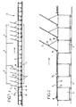
- FIG. 1 represents a cooking installation comprising a tunnel oven comprising three zones, a zone 2 for starting cooking, a maximum cooking zone 3 or full fire zone, in which the articles are brought to a plastic state, and a cooling zone 4.
- the articles not shown in the drawing, are placed on supports 5 themselves resting on bases 6 constituted by carriages movable on rails 7.
- the station for loading articles on supports is designated by reference 8, and the unloading station is designated by reference 9.
- each support 5 is tiltable relative to the base 6 with which it is associated, between a substantially horizontal position and a substantially horizontal position vertical.
- each support is pivotally mounted around an axis 10, horizontal and transverse to the direction of movement of the supports.
- the hinge pin 10 is located at one end of the support 5, near one end of a carriage 6.
- the length of the support 5 is greater than that of the carriage 6, so that the support protrudes longitudinally from the carriage, when the support is in a substantially horizontal position.
- each support 5 On the rear face of each support 5 is articulated, around an axis 12 parallel to the axis 10, at least one connecting rod 13 of which the other end is articulated around an axis 14 parallel to axis 12, on the carriage 4 arranged forward or backward in the direction of movement of the carts. Consequently, when the carriages are moved apart, the supports 5 are substantially in a horizontal position, as shown in section left of figure 2, while when the carriages are brought together others, the pivoting of the connecting rods 13 brings the supports 5 in a tilted position approaching the vertical, as shown in section right of figure 2.
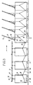
- FIG. 3 represents an alternative embodiment in which the same elements are designated by the same references as previously.
- each support 5 is not articulated directly on the carriage, but on lugs 15 integral with the carriage, this which allows the support to be raised relative to the carriage.
- the pivoting movement of each support is obtained using a connecting rod 16 always remaining in a vertical position, one end of which is articulated on the rear face of the support 5, at 17, and the other end of which is articulated at 18, always around a transverse, horizontal and transverse to the movement of the carriages, on two connecting rods 19 and 20, the connecting rod 19 being articulated about an axis 22 of the same orientation as the previous on the carriage 6 considered, and the other end of the connecting rod 20 being articulated around an axis 23 on a neighboring carriage.
- the mode of inclination of the supports results, as previously, from the carriage alignment or spacing.
- each support is equipped with a lever 24, of which it is integral, this lever 24 being likely to bear on a ramp 25 arranged next to the rails of movement of the carriages 6 and forming a cam, in the areas where the support must be tilted to a position approaching the vertical.
- the invention provides a great improvement to the existing technique, providing a process and a device for firing ceramic products inside an oven tunnel, allowing to reconcile the advantages of precision of the articles undergoing flat cooking, and compactness of the devices in which the articles are arranged in an inclined position.
- the invention is not limited to only embodiments of this device described above by way of examples, the scope of the invention being determined by the claims. This is how that the bases of the supports may not be constituted by trolleys, but by trays moved for example through a transporter, without thereby departing from the scope of the invention.
Landscapes
- Engineering & Computer Science (AREA)
- Mechanical Engineering (AREA)
- General Engineering & Computer Science (AREA)
- Furnace Charging Or Discharging (AREA)
- Baking, Grill, Roasting (AREA)
- Tunnel Furnaces (AREA)
- Furnace Details (AREA)
Claims (9)
- Brennverfahren für keramische Erzeugnisse in einem Ofen, das aufweist: Plazieren jedes Erzeugnisses auf einem Träger, dessen anschließendes Einbringen ins Innere eines Ofens zur Durchführung des Brennens, dadurch gekennzeichnet, daß es aufweist: Plazieren jedes Erzeugnisses auf einem Träger (5), der zwischen einer im wesentlichen horizontalen Position und einer im wesentlichen vertikalen Position neigbar ist, und Verändern der Neigung des Trägers (5) während des Verschiebens des Trägers, damit dieser zumindest in der Zone (3) des Ofens, in dem die Temperatur derart ist, daß das zu brennende Erzeugnis plastisch wird, im wesentlichen horizontal ist.
- Brennverfahren nach Anspruch 1, dadurch gekennzeichnet, daß es aufweist: Verändern des Abstands zwischen zwei aufeinanderfolgenden Trägern (5) in deren Verschiebungsrichtung in der Art, daß der Abstand zwischen den Trägern (5) zunimmt, wenn die Träger in der Horizontalen gekippt sind, und abnimmt, wenn sie in der Vertikalen gekippt sind.
- Brennverfahren nach Anspruch 2, dadurch gekennzeichnet, daß es das Einwirken auf den Abstand zwischen den Trägern (5), um deren Neigung zu verändern, aufweist.
- Brennverfahren nach einem der Ansprüche 1 bis 3, dadurch gekennzeichnet, daß es aufweist: im wesentlichen horizontales Positionieren jedes Trägers (5) an der Beladungsstelle (8) für die Erzeugnisse, dann deren Kippen in eine geneigte Position, wobei diese geneigte Position während der Verlagerung des Trägers ins Innere des Ofens aufrechterhalten wird, deren Kippen in eine im wesentlichen horizontale Position in der Zone (3) mit der maximalen Heizung oder in der Zone der Temperatur, bei der das Erzeugnis in einem formbaren Zustand ist, und schließlich das Bringen in eine geneigte Position bis zur Entnahmestelle (9), wo der Träger wieder in die flache Lage gebracht wird.
- Brennanlage für keramische Erzeugnisse in einem Ofen, die Träger für die Erzeugnisse aufweist, dadurch gekennzeichnet, daß jeder Erzeugnisträger (5) auf einem beweglichen Sockel (6), wie etwa einem Wagen, um eine horizontale und zur Richtung der Verschiebung der Träger transversale Achse (10) schwenkbar montiert ist, wobei Einrichtungen vorgesehen sind, die während der Verschiebung des Sockels das Schwenken jedes Trägers um seine Achse herum sicherstellen.
- Anlage nach Anspruch 5, dadurch gekennzeichnet, daß sie Einrichtungen zum Einstellen des Abstands zwischen den Sockeln der Träger aufweist, wobei die Länge der Sockel geringer als die Länge der Träger ist.
- Anlage nach einem der Ansprüche 5 und 6, dadurch gekennzeichnet, daß jeder Träger (5) mit einer Reihe von parallelen gelenkigen Steuergestängen (13, 16, 19, 20) einerseits auf der Seite unter dem Träger und andererseits auf dem Sockel des benachbarten Trägers um die horizontalen und zur Richtung der Verschiebung der Träger transversalen Achsen (12, 14, 17, 18, 22, 23) herum ausgestattet ist.
- Anlage nach einem der Ansprüche 5 und 6, dadurch gekennzeichnet, daß jeder Träger (5) auf seiner unteren Seite mit einem Hebel (24) ausgestattet ist, der fest verbunden mit dem Träger montiert ist, und Nocken bildende Profilelemente (25) unterhalb des Wegs der Träger (5) angeordnet sind, wobei das freie Ende des Hebels sich auf die Profilelemente stützt, um den betrachteten Träger zu schwenken.
- Anlage nach Anspruch 6, dadurch gekennzeichnet, daß die Einrichtungen zum Einstellen des Abstands zwischen den Trägersockeln durch die Antriebseinrichtungen zur Verschiebung der Sockel gebildet werden.
Applications Claiming Priority (2)
| Application Number | Priority Date | Filing Date | Title |
|---|---|---|---|
| FR9807260 | 1998-06-05 | ||
| FR9807260A FR2779513B1 (fr) | 1998-06-05 | 1998-06-05 | Procede de cuisson d'articles ceramiques dans un four tunnel |
Publications (2)
| Publication Number | Publication Date |
|---|---|
| EP0962733A1 EP0962733A1 (de) | 1999-12-08 |
| EP0962733B1 true EP0962733B1 (de) | 2003-07-30 |
Family
ID=9527198
Family Applications (1)
| Application Number | Title | Priority Date | Filing Date |
|---|---|---|---|
| EP99420129A Expired - Lifetime EP0962733B1 (de) | 1998-06-05 | 1999-06-04 | Brennverfahren und Brennanlage für keramische Erzeugnisse im Tunnelofen |
Country Status (4)
| Country | Link |
|---|---|
| EP (1) | EP0962733B1 (de) |
| AT (1) | ATE246331T1 (de) |
| DE (1) | DE69909896D1 (de) |
| FR (1) | FR2779513B1 (de) |
Family Cites Families (4)
| Publication number | Priority date | Publication date | Assignee | Title |
|---|---|---|---|---|
| DE580493C (de) * | 1927-06-30 | 1933-07-12 | William Joseph Miller | Fortlaufend angetriebener endloser biegsamer Foerderer |
| DE3425625A1 (de) * | 1984-07-12 | 1986-01-16 | Andreas Ing.(grad.) 7904 Erbach Häßler | Verfahren und vorrichtung zum transportieren und trocknen von tondachziegeln |
| DE3914509A1 (de) * | 1989-05-02 | 1991-01-10 | Keller Gmbh & Co Kg | Aufnahmevorrichting / kassette zum trocknen von im querschnitt winkel-oder bogenfoermigen keramischen dachziegel-formlingen |
| EP0786636A1 (de) * | 1996-01-26 | 1997-07-30 | Keller GmbH | Verfahren und Ofenwagen zum Brennen von Falzdachziegeln |
-
1998
- 1998-06-05 FR FR9807260A patent/FR2779513B1/fr not_active Expired - Fee Related
-
1999
- 1999-06-04 DE DE69909896T patent/DE69909896D1/de not_active Expired - Lifetime
- 1999-06-04 EP EP99420129A patent/EP0962733B1/de not_active Expired - Lifetime
- 1999-06-04 AT AT99420129T patent/ATE246331T1/de not_active IP Right Cessation
Also Published As
| Publication number | Publication date |
|---|---|
| EP0962733A1 (de) | 1999-12-08 |
| FR2779513A1 (fr) | 1999-12-10 |
| FR2779513B1 (fr) | 2000-08-11 |
| ATE246331T1 (de) | 2003-08-15 |
| DE69909896D1 (de) | 2003-09-04 |
Similar Documents
| Publication | Publication Date | Title |
|---|---|---|
| FR2612917A1 (fr) | Procede et appareillage de profilage de feuilles de verre, notamment de glaces pour automobiles | |
| EP0709343B1 (de) | Kontinuierlichen Ofen zum Heizen von Glasscheiben auf Biege- und/oder Härtungstemperatur | |
| FR2478066A1 (fr) | Procede et dispositif pour le formage de feuilles de verre a l'aide d'un moule a vide deformable | |
| FR2465692A1 (fr) | Procede et dispositif de faconnage de feuilles de verre a l'aide de moules de formes differentes | |
| LU86906A1 (fr) | Procede e appareil de cambrage de feuilles de verre | |
| EP0626230B1 (de) | Vorrichtung zum Führen und Fördern von mindestens zwei angedockenden Blechen, und Schweissanlage mit solcher Vorrichtung | |
| EP3512343B1 (de) | Kochmodul für einen linearen tunnelofen für backwaren, feingebäck und dergleichen und linearer tunnelofen mit mindestens einem solchen modul | |
| FR2609283A1 (fr) | Appareillage et procede pour profiler une feuille de verre ramollie par chauffage | |
| EP0962733A1 (de) | Brennverfahren für keramische Erzeugnisse im Tunnelofen | |
| FR2638155A1 (fr) | Procede et dispositif pour cintrer et recuire des feuilles de verre a feuilleter | |
| FR2516502A1 (fr) | Procede et dispositif pour extraire des feuilles de verre cintrees et trempees d'un poste de refroidissement | |
| FR2694165A1 (fr) | Machine pour l'épluchage de salades. | |
| FR2651771A1 (fr) | Dispositif pour donner un profil desire a une feuille de verre, et procede de mise en óoeuvre du dispositif. | |
| EP0299869B1 (de) | Biegen von Glasscheiben | |
| EP0219520B1 (de) | Transportwagen für platten, insbesondere für gefriertrocknung sowie entsprechende lade-/entladevorrichtung | |
| EP0244305B1 (de) | Transfer von Scheiben von einem Transportband zu einem anderen und Anwendung beim Biegen von Glasscheiben | |
| EP0451010A1 (de) | Vorrichtung zum Beheizen, Formen und Tempern von Glastafeln | |
| BE1013806A3 (fr) | Four. | |
| EP0250311A1 (de) | Verfahren und Vorrichtung zum Biegen von Glasplatten | |
| EP1853116B1 (de) | Bäckereiofen mit einem gewebe-förderband | |
| CH393146A (fr) | Installation pour revêtir d'un vernis polymérisé l'intérieur de tubes d'emballage métalliques ou autres objets tubulaires | |
| FR2470351A1 (fr) | Chariot destine au transfert d'articles d'argile ou materiaux ceramiques analogues dans un four de cuisson | |
| FR3154287A1 (fr) | Systeme de culture verticale | |
| EP4007684A1 (de) | Verfahren zum erwärmen mindestens eines teils einer innenfläche eines holzbehälters und vorrichtung zur durchführung des verfahrens | |
| BE563982A (de) |
Legal Events
| Date | Code | Title | Description |
|---|---|---|---|
| PUAI | Public reference made under article 153(3) epc to a published international application that has entered the european phase |
Free format text: ORIGINAL CODE: 0009012 |
|
| AK | Designated contracting states |
Kind code of ref document: A1 Designated state(s): AT BE DE ES FR GB GR IT PT |
|
| AX | Request for extension of the european patent |
Free format text: AL;LT;LV;MK;RO;SI |
|
| 17P | Request for examination filed |
Effective date: 20000608 |
|
| AKX | Designation fees paid |
Free format text: AT BE DE ES FR GB GR IT PT |
|
| RTI1 | Title (correction) |
Free format text: FIRING PROCESS AND DEVICE FOR CERAMIC ARTICLES IN A TUNNEL FURNACE |
|
| GRAH | Despatch of communication of intention to grant a patent |
Free format text: ORIGINAL CODE: EPIDOS IGRA |
|
| RTI1 | Title (correction) |
Free format text: FIRING PROCESS AND DEVICE FOR CERAMIC ARTICLES IN A TUNNEL FURNACE |
|
| GRAH | Despatch of communication of intention to grant a patent |
Free format text: ORIGINAL CODE: EPIDOS IGRA |
|
| GRAA | (expected) grant |
Free format text: ORIGINAL CODE: 0009210 |
|
| AK | Designated contracting states |
Designated state(s): AT BE DE ES FR GB GR IT PT |
|
| PG25 | Lapsed in a contracting state [announced via postgrant information from national office to epo] |
Ref country code: IT Free format text: LAPSE BECAUSE OF FAILURE TO SUBMIT A TRANSLATION OF THE DESCRIPTION OR TO PAY THE FEE WITHIN THE PRESCRIBED TIME-LIMIT;WARNING: LAPSES OF ITALIAN PATENTS WITH EFFECTIVE DATE BEFORE 2007 MAY HAVE OCCURRED AT ANY TIME BEFORE 2007. THE CORRECT EFFECTIVE DATE MAY BE DIFFERENT FROM THE ONE RECORDED. Effective date: 20030730 Ref country code: GB Free format text: LAPSE BECAUSE OF FAILURE TO SUBMIT A TRANSLATION OF THE DESCRIPTION OR TO PAY THE FEE WITHIN THE PRESCRIBED TIME-LIMIT Effective date: 20030730 Ref country code: AT Free format text: LAPSE BECAUSE OF FAILURE TO SUBMIT A TRANSLATION OF THE DESCRIPTION OR TO PAY THE FEE WITHIN THE PRESCRIBED TIME-LIMIT Effective date: 20030730 |
|
| REG | Reference to a national code |
Ref country code: GB Ref legal event code: FG4D Free format text: NOT ENGLISH |
|
| REF | Corresponds to: |
Ref document number: 69909896 Country of ref document: DE Date of ref document: 20030904 Kind code of ref document: P |
|
| PG25 | Lapsed in a contracting state [announced via postgrant information from national office to epo] |
Ref country code: GR Free format text: LAPSE BECAUSE OF FAILURE TO SUBMIT A TRANSLATION OF THE DESCRIPTION OR TO PAY THE FEE WITHIN THE PRESCRIBED TIME-LIMIT Effective date: 20031030 |
|
| PG25 | Lapsed in a contracting state [announced via postgrant information from national office to epo] |
Ref country code: DE Free format text: LAPSE BECAUSE OF FAILURE TO SUBMIT A TRANSLATION OF THE DESCRIPTION OR TO PAY THE FEE WITHIN THE PRESCRIBED TIME-LIMIT Effective date: 20031031 |
|
| PG25 | Lapsed in a contracting state [announced via postgrant information from national office to epo] |
Ref country code: ES Free format text: LAPSE BECAUSE OF FAILURE TO SUBMIT A TRANSLATION OF THE DESCRIPTION OR TO PAY THE FEE WITHIN THE PRESCRIBED TIME-LIMIT Effective date: 20031110 |
|
| PG25 | Lapsed in a contracting state [announced via postgrant information from national office to epo] |
Ref country code: PT Free format text: LAPSE BECAUSE OF FAILURE TO SUBMIT A TRANSLATION OF THE DESCRIPTION OR TO PAY THE FEE WITHIN THE PRESCRIBED TIME-LIMIT Effective date: 20031230 |
|
| GBV | Gb: ep patent (uk) treated as always having been void in accordance with gb section 77(7)/1977 [no translation filed] |
Effective date: 20030730 |
|
| REG | Reference to a national code |
Ref country code: FR Ref legal event code: CD |
|
| PLBE | No opposition filed within time limit |
Free format text: ORIGINAL CODE: 0009261 |
|
| STAA | Information on the status of an ep patent application or granted ep patent |
Free format text: STATUS: NO OPPOSITION FILED WITHIN TIME LIMIT |
|
| PG25 | Lapsed in a contracting state [announced via postgrant information from national office to epo] |
Ref country code: BE Free format text: LAPSE BECAUSE OF NON-PAYMENT OF DUE FEES Effective date: 20040630 |
|
| 26N | No opposition filed |
Effective date: 20040504 |
|
| BERE | Be: lapsed |
Owner name: *REFRACTAIRES ET CONCEPTS CERAMIQUES Effective date: 20040630 |
|
| PGFP | Annual fee paid to national office [announced via postgrant information from national office to epo] |
Ref country code: FR Payment date: 20090615 Year of fee payment: 11 |
|
| REG | Reference to a national code |
Ref country code: FR Ref legal event code: ST Effective date: 20110228 |
|
| PG25 | Lapsed in a contracting state [announced via postgrant information from national office to epo] |
Ref country code: FR Free format text: LAPSE BECAUSE OF NON-PAYMENT OF DUE FEES Effective date: 20100630 |