EP0962836B1 - Bilderzeugungsvorrichtung - Google Patents
Bilderzeugungsvorrichtung Download PDFInfo
- Publication number
- EP0962836B1 EP0962836B1 EP97942210A EP97942210A EP0962836B1 EP 0962836 B1 EP0962836 B1 EP 0962836B1 EP 97942210 A EP97942210 A EP 97942210A EP 97942210 A EP97942210 A EP 97942210A EP 0962836 B1 EP0962836 B1 EP 0962836B1
- Authority
- EP
- European Patent Office
- Prior art keywords
- transfer roller
- image
- print sheet
- transfer
- forming device
- Prior art date
- Legal status (The legal status is an assumption and is not a legal conclusion. Google has not performed a legal analysis and makes no representation as to the accuracy of the status listed.)
- Expired - Lifetime
Links
Images




Classifications
-
- G—PHYSICS
- G03—PHOTOGRAPHY; CINEMATOGRAPHY; ANALOGOUS TECHNIQUES USING WAVES OTHER THAN OPTICAL WAVES; ELECTROGRAPHY; HOLOGRAPHY
- G03G—ELECTROGRAPHY; ELECTROPHOTOGRAPHY; MAGNETOGRAPHY
- G03G15/00—Apparatus for electrographic processes using a charge pattern
- G03G15/14—Apparatus for electrographic processes using a charge pattern for transferring a pattern to a second base
- G03G15/16—Apparatus for electrographic processes using a charge pattern for transferring a pattern to a second base of a toner pattern, e.g. a powder pattern, e.g. magnetic transfer
-
- G—PHYSICS
- G03—PHOTOGRAPHY; CINEMATOGRAPHY; ANALOGOUS TECHNIQUES USING WAVES OTHER THAN OPTICAL WAVES; ELECTROGRAPHY; HOLOGRAPHY
- G03G—ELECTROGRAPHY; ELECTROPHOTOGRAPHY; MAGNETOGRAPHY
- G03G15/00—Apparatus for electrographic processes using a charge pattern
- G03G15/14—Apparatus for electrographic processes using a charge pattern for transferring a pattern to a second base
- G03G15/16—Apparatus for electrographic processes using a charge pattern for transferring a pattern to a second base of a toner pattern, e.g. a powder pattern, e.g. magnetic transfer
- G03G15/1665—Apparatus for electrographic processes using a charge pattern for transferring a pattern to a second base of a toner pattern, e.g. a powder pattern, e.g. magnetic transfer by introducing the second base in the nip formed by the recording member and at least one transfer member, e.g. in combination with bias or heat
- G03G15/167—Apparatus for electrographic processes using a charge pattern for transferring a pattern to a second base of a toner pattern, e.g. a powder pattern, e.g. magnetic transfer by introducing the second base in the nip formed by the recording member and at least one transfer member, e.g. in combination with bias or heat at least one of the recording member or the transfer member being rotatable during the transfer
-
- G—PHYSICS
- G03—PHOTOGRAPHY; CINEMATOGRAPHY; ANALOGOUS TECHNIQUES USING WAVES OTHER THAN OPTICAL WAVES; ELECTROGRAPHY; HOLOGRAPHY
- G03G—ELECTROGRAPHY; ELECTROPHOTOGRAPHY; MAGNETOGRAPHY
- G03G2215/00—Apparatus for electrophotographic processes
- G03G2215/00953—Electrographic recording members
- G03G2215/00962—Electrographic apparatus defined by the electrographic recording member
- G03G2215/00974—Electrographic recording member arranged as a carriage to be movable in a direction perpendicular to the recording sheet transport direction
Definitions
- the present invention relates to an image forming device which transfers a toner image from a belt shaped toner image carrying member to a print sheet by means of a roller.
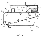
- Fig. 9 is a diagrammatic sketch of a prior art image forming device of quadrature transfer system
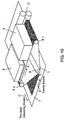
- Fig. 10 is a perspective view of the foregoing image forming device
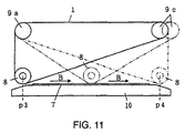
- Fig. 11 is a diagram to show the transfer state of an transfer roller of the foregoing image forming device.
- Fig. 9 is a diagrammatic sketch of a prior art image forming device of quadrature transfer system
- Fig. 10 is a perspective view of the foregoing image forming device
- Fig. 11 is a diagram to show the transfer state of an transfer roller of the foregoing image forming device.
- the reference symbol 1 is a photosensitive belt
- the reference symbol 2 is a charging unit
- the reference symbol 3 is an image developer
- the reference symbol 3a is toner
- the reference symbol 3b is an image development roller
- the reference symbol 3c is a toner image
- the reference symbol 4 is a photosensitive belt cleaner
- the reference symbol 5 is a discharging unit
- the reference symbol 6 is a light exposure unit
- the reference symbol 7 is a print sheet
- the reference symbol 8 is an transfer roller
- the reference symbols 9a to 9c are supporting rollers
- the reference symbol 10 is a transfer plate
- the reference symbol 11 is a print sheet transporting roller.
- a closed loop belt like shape photosensitive belt 1 the surface of which is coated with an organic photoconductive material, is supported by supporting rollers 9a to 9c and a transfer roller 8 and also made movable rotationally in the direction of an arrow A.
- a photosensitive material cleaner 4, a discharging unit 5, a charging unit 2, a light exposure unit 6 and an image developer 3 are arranged in this order along the direction of a rotational movement of the photosensitive belt 1, and further toner 3a is contained inside of the image developer 3.
- a print sheet 7 is supported by a transfer plate 10 and transported in the direction C perpendicular to the rotational direction A of the photosensitive belt 1 by a print sheet transporting roller 11 as shown in Fig. 10.
- a supporting roller driving means such as a motor and the like make the supporting rollers 9a to 9c rotate, thereby starting the rotation of the photosensitive belt 1 in the direction of the arrow A.
- the photosensitive belt 1 has the surface thereof charged by the charging unit 2 and then an electrostatic latent image is formed on the charged surface by laser light 6a irradiated from the light exposure unit 6 according to the content of an image to be formed.
- an image development roller 3b installed in the image developer 3 is rotated by an image development roller driving means such as a motor and the like and at the same time brought into contact with the photosensitive belt 1. Accordingly, while the photosensitive belt 1 is sandwiched and moved between the image development roller 3b and the supporting roller 9b, the electrostatic latent image is developed by the toner 3a attached to the surface of the image development roller 3b and a toner image 3c is formed on the photosensitive belt 1.
- the toner image 3c is transferred from the photosensitive belt 1 to the print sheet 7.
- the rotation of the supporting rollers 9a to 9c is suspended with a resulting stop of the rotational movement of the photosensitive belt 1 when a tip p 1 (Fig. 9) of the toner image 3c formed on the photosensitive belt 1 arrives at almost the same position as an end p 2 of the image forming area of the print sheet 7.
- the print sheet transporting roller 11 is rotated by a print sheet transporting roller driving means such as a motor and the like and the print sheet 7 is transported on the transfer plate 10 in the direction C (print sheet transporting direction) perpendicular to the direction A of the rotational movement of the photosensitive belt 1 to a specified position.
- the transfer roller 8 is moved horizontally along the surface of the print sheet 7 in the direction of an arrow B as shown in Fig. 10 and Fig. 11 from a transfer starting position p 3 to a transfer ending position p 4 (Fig. 11). While this horizontal travel of the transfer roller 8 is taking place, the toner image 3c on the photosensitive belt 1 is transferred on the print sheet 7 through consecutive steps of having the photosensitive belt 1 pressed against the print sheet 7 by the transfer roller 8.
- the print sheet transporting roller 11 starts to rotate again and the print sheet 7, on which an image is formed, is rolled out.
- the photosensitive belt 1 starts to move again, the area, where the toner image 3c was transferred on the photosensitive belt 1, gets rid of the toner that remained on the photosensitive belt 1 by means of the photosensitive belt cleaner 4 and then the electric charge that remained on the photosensitive belt 1 is made to disappear by means of the discharging unit 5.
- a given image such as lettering, graphics and the like is formed on the single sheet of the print sheet 7, and the same image forming process as above is repeated in succession as needed.
- Fig. 12 is a diagrammatic sketch of a prior art image forming device of parallel transfer system
- Fig. 13 is a perspective view of the image forming device of Fig. 12
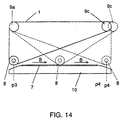
- Fig. 14 is a dia- gram to show the transfer state of the transfer roller of the image forming device of Fig. 12.
- an explanation will be made only on the part where the foregoing image forming device differs from the previously described image forming device of quadrature transfer system.
- a photosensitive belt 1 is wound around supporting rollers 9a, 9b and 9c that are rotated by means of a motor and the like so as to make the photosensitive belt 1 movable in the direction indicated by an arrow A.
- the movement direction of this photosensitive belt 1 is the same as the feeding direction of a print sheet 7 that is supplied onto a transfer plate 10 by means of a print sheet transporting roller 11, and the print sheet 7 is supported by the transfer plate 10 and transported in the same direction as the photosensitive belt 1 is moved by means of the print sheet transporting roller 11 as shown in Fig. 13.
- the print sheet transporting roller 11 is rotated by a driving means such as a motor and the like, thereby transporting the print sheet 7 on the surface of the transfer plate 10 in the same direction as the moving direction of the photosensitive belt 1 to a specified position.
- a driving means such as a motor and the like
- an transfer roller 8 is moved horizontally on the surface of the print sheet 7 in the direction indicated by an arrow B in Fig. 14 from a transfer starting position p 3 to a transfer ending position p 4.
- this transfer roller 8 While the horizontal travel of this transfer roller 8 is taking place, the toner image 3c on the photosensitive belt 1 is transferred onto the print sheet 7 through consecutive steps of having the photosensitive belt 1 pressed against the print sheet 7 by the transfer roller 8, thereby forming a printed image 3d on the print sheet 7 as shown in Fig. 13. Further, when the transfer roller 8 has arrived at the transfer ending position p 4, the transfer roller 8 starts to move in the reversed direction and returns to the transfer starting position p 3.
- the transfer roller 8 travels the maximum width between p 3 and p 4 even if a small sized print sheet is used, thereby causing the extra amount of toner left on the photosensitive belt 1 at the place, where no pressing on the print sheet takes place, to get shifted toward the transfer plate 10. Thereafter, when a large sized print sheet 7 is used, the toner shifted onto the transfer plate 10 is attached to the back side surface of the print sheet 7 to present a problem of form a smear (back smear). Further, regardless of the size of the image to be printed, the traveling distance of the transfer roller 8 remains the same and so the time required for image transferring also remains the same, resulting in a problem of reduced efficiency.
- a similar printer device is disclosed in EP-A-0 466 127.
- a toner belt is pressed to a print medium by a transfer member. After printing one image line, the transfer member reverses its direction to transfer a further image line.
- EP-A-0 698 833 describes a toner transfer apparatus, wherein a toner image is transferred from a belt to a print medium by a transfer roller.
- a sensor at the transfer roller detects when the belt is at a specified position in order to start the transfer operation.
- the end position of the transfer roller depends on the width of the print medium and the associated length of the image strip to be transferred.
- a serial printer is shown in US-A-5 594 530.
- This printer comprises a process part that transfers and fixes toner to a paper.
- the process part comprises sensors to detect the edges of the print medium in order to determine a print start and stop position.
- JP-A-63 054267 describes a printing device which detects the width of printing paper and controls a printing head to move only within a specific region determined by the detected paper width.
- Fig. 1 is a perspective view of an image forming device of quadrature transfer system in a first exemplary embodiment useful for the understanding of the present invention
- Fig. 2 is a diagram to show a state of movement of an transfer roller when a print sheet is small in width
- Fig. 3 is a diagram to show a state of movement of the opposed transfer roller when the print sheet is large in width.
- the reference symbol 1 is a photosensitive belt
- the reference symbol 3 is an image developer
- the reference symbol 6 is a light exposure unit
- the reference symbol 7 is a print sheet
- the reference symbol 8 is an transfer roller
- the reference symbols 9a to 9c are supporting rollers
- the reference symbol 10 is a transfer plate
- the reference symbol 11 is a print sheet transporting roller.
- a closed loop belt like shape photosensitive belt 1 the surface of which is coated with an organic photoconductive material, is supported by supporting rollers 9a to 9c and an transfer roller 8 and also made movable rotationally in the direction of an arrow A.
- a light exposure unit 6 and an image developer 3 are arranged in this order along the direction of rotational movement of the photosensitive belt 1.
- a print sheet 7 is supported by a transfer plate 10 and transported in the direction C perpendicular to the rotational direction A of the photosensitive belt 1 by a print sheet transporting roller 11 as shown in Fig. 1.
- the reference symbols 12a and 12b are print sheet feeding guides and the reference symbol 13 is an transfer roller detector for detecting the transfer roller 8 in order to have the direction of the forward moving transfer roller 8 (the direction indicated by an arrow B) reversed, namely making a U-turn from forward to backward.
- a photosensitive roller driving means such as a motor and the like makes the supporting rollers 9a to 9c rotate, thereby starting a rotational movement of the photosensitive belt 1 in the direction of an arrow A.
- the photosensitive belt 1 has the surface thereof charged by means of the charging unit 2 and then an electrostatic latent image is formed on the charged surface by laser light 6a irradiated from the light exposure unit 6 according to the content of the image to be formed.
- the electrostatic latent image is developed by toner and a toner image is formed on the photosensitive belt 1.
- the toner image is transferred from the photosensitive belt 1 onto the print sheet 7.
- the print sheet feeding guide 12a is fixed while one side of the print sheet 7 is always to be kept in touch with the print sheet feeding guide 12a.
- the print sheet feeding guide 12b can be changed in position to match the size of the print sheet 7.
- This print sheet feeding guide 12b is interlocked with the transfer roller detector 13, which is moved from side to side in synchronization with the movement of the print sheet feeding guide 12b along a guide formed of a shaft and the like.
- the transfer roller detector 13 detects the transfer roller 8 that is moving in the direction of the arrow B (forward moving direction), the transfer roller 8 moves in the direction opposite (backward direction) to the direction of the arrow B (forward direction) and returns back to the original waiting position.
- the transfer roller detector 13 moves toward the inside as shown in Fig. 2 and the transfer roller 8 starts turning back at the position shown in Fig. 2.
- the transfer roller detector 13 remains staying at the end position and the transfer roller 8 turns back after having shifted to the largest extent as shown in Fig. 3.
- the print sheet transporting roller 11 Upon completion of the transfer of the toner image, the print sheet transporting roller 11 is rotated in the reversed direction and the print sheet 7, on which an image is formed, is rolled out.
- the photosensitive belt 1 starts to rotate again, the area, where the toner image 3c was transferred on the photosensitive belt 1, gets rid of the toner that remained on the photosensitive belt 1 by means of a photosensitive belt cleaner and then the electric charge that remained on the photosensitive belt 1 is made to disappear by means of a discharging unit.
- a given image such as lettering, graphics and the like is formed on a single sheet of the print sheet 7, and the same image forming process as above is repeated in succession as needed.
- shifting of the transfer roller 8 in position is made possible in accordance with the size of the print sheet 7 and transferring of a toner image on a transfer plate 10 by the movement of the transfer roller 8 beyond the area occupied by the print sheet 7 can be prevented from taking place, thereby eliminating the problem of a back smear associated with a print sheet.
- An image forming device of quadrature transform system in a second exemplary embodiment of the present invention differs from the one in the first exemplary embodiment in the way that a controller, whereby an transfer roller detector 13 is moved from side to side, operates.
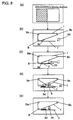
- FIG. 4(a) to Fig. 4(e) illustrate how the image forming device in the present exemplary embodiment operates.
- An area for image data is shown in Fig. 4(a)
- a toner image that corresponds to the area for image data of Fig. 4(a) is shown in Fig. 4(b)
- an transfer roller detector the position of which is determined in accordance with the toner image of Fig. 4(b)
- a state of movement of a transfer roller 8 is shown in each of Fig. 4 (d) and Fig. 4(e).
- the toner image 3c, print sheet 7, transfer roller 8 and transfer roller detector 13 are the same as indicated in Fig. 1 to Fig. 3, and therefore the same reference symbols are assigned thereto as used in Fig. 1 to Fig. 3 with a specific description of each item omitted.
- the reference symbol 14 shows the area for image data in an image data storing memory 15.
- the size (width) of an image formed on a photosensitive belt 1 is determined by an image data amount detector 14 contained in the image data storing memory 15.
- a controller (not shown in the drawings) calculates the size of the image and make the transfer roller detector 13 move so as to have the transfer roller 8 shifted in position by the amount corresponding to the size of the image, (Fig. 4(c)). Then, only the area where the toner image 3c exists is transferred when transferring is performed by having the transfer roller 8 moved, (Fig. 4(d)), and the transfer roller 8 is moved in a reversed direction (backward direction), returning back to the original waiting position as shown in Fig. 4(e).
- an transfer roller detector 13 was used in the first and second exemplary embodiments of the present invention for detecting the position of an transfer roller 8, the detection might be carried out by utilizing the count of pulses generated in accordance with the amount of rotation of the transfer roller 8.
- the transfer roller 8 is made to move in the forward direction by an amount equal to the size (width) of an image and to start returning in the backward direction at the moment when the transfer roller 8 has traveled the distance equal to the size of the image, thereby enabling the shifting of the transfer roller 8 over the distance matching the size of the image to be printed and the reduction in a period of time required for image transferring when the image to be printed is small.
- Fig. 5 is a cross-sectional view of an image forming device of parallel transfer system in a third exemplary embodiment of the present invention to show a state of movement of an transfer roller when the amount of image data is small
- Fig. 6 is a cross-sectional view of the image forming device of parallel transfer system of Fig. 5 to show a state of movement of the opposed transfer roller when the amount of image data is large
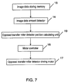
- Fig. 7 is a control block diagram of the image forming device of parallel transfer system in the third exemplary embodiment of the present invention.
- the component of the reference symbol 20 is an transfer roller detector which is movable by traversing in parallel with the shifting direction of an transfer roller 8.
- This transfer roller detector 20 has an transfer roller detector driving motor 17 built in so as to run freely horizontally by self-propelling at a position a little apart from the edge of a photosensitive belt 1, the edge being situated in the direction of the width of the photosensitive belt 1.
- the output shaft of the transfer roller detector driving motor 17 is kept in contact with a guide rail, for example, (not shown in the drawings) that is positioned in parallel with the upper surface of a transfer plate 10, thus allowing the transfer roller detector 20 to traverse according to the rotational direction of the foregoing output shaft.
- a contacting member 20a to hit a protruding shaft 8a projected from the end of the transfer roller 8 is provided on the transfer roller detector 20, thereby making it possible to provide a signal, which is produced by the contacting member 20a at the time of hitting the protruding shaft 8a, to the input of a controller.
- the reference symbol 18 is an image data storing memory
- the reference symbol 14 is an image data amount detector to obtain the size of an image formed on the photosensitive belt 1 by calculation based on the size of the image data stored in the image data storing memory
- the reference symbol 19 is an transfer roller detector position calculating unit to calculate the amount of rotation for the transfer roller detector driving motor 17 to have the transfer roller 8 moved in accordance with the size of image obtained by calculation in the image data amount detector 14
- the reference symbol 16 is a motor controller to move the transfer roller detector 20 of the transfer roller 8 by driving the transfer roller detector driving motor 17 by an amount of rotation obtained by calculation in the transfer roller detector position calculating unit 19.
- Fig. 8 shows diagrams describing the performance of the image forming device of parallel transfer system in the present exemplary embodiment when the stroke, or the width of shifting, of the transfer roller is changed according to the amount of image data.
- the position of a toner image 3c to be formed on the photosensitive belt 1 is determined so as to correspond to the foregoing area and when the area of the photosensitive belt 1, where the toner image 3c is transported, arrives at the position opposing to the print sheet 7 as shown in Fig. 8(b), the photosensitive belt 1 comes to a stop.
- the size of the image to be formed on the photosensitive belt 1 is calculated by feeding the image data relative to the foregoing toner image 3c into the image data amount detector 14.
- the result of this calculation is fed into the transfer roller detector position calculating unit 19 to have the amount of shifting of the transfer roller detector 20 calculated in order for the transfer roller detector 20 to move to the position where the transfer roller 8 comes to a stop after travling the distance to cover the size of a developed image.
- the rotational amount of the output shaft of the transfer roller detector driving motor 17 is obtained by calculation in order for the transfer roller detector 20 to travel a given distance and the motor controller 16 controls the transfer roller detector driving motor 17 accordingly.
- the transfer roller detector driving motor 17 By controlling the amount of shifting of the transfer roller detector driving motor 17 as described in the above, the transfer roller detector driving motor 17 is moved to the position as indicated in Fig. 8(c). Then, the transfer roller 8 is driven to move toward right side as indicated in Fig. 8(d), thereby having only the area, where the toner image 3c has been formed, transferred onto the print sheet 7 to have an image 3d formed thereon.
- the transfer roller detector 20 travels a sufficient distance for the transfer roller 8 to form the image 3d, and gets to and stays at the position, where the contacting member 20a thereof hits the protruding shaft 8a of the transfer roller 8. Therefore, when the protruding shaft 8a comes into contact with the contacting member 20a, the transfer roller 8 stops for a moment and moves in the reversed direction to return to the original waiting position as shown in Fig. 8(e).
- the transfer roller detector 20 is moved to almost the middle position of the transfer plate 10 and the transfer roller 8 is stopped halfway and then returned to the original position. Accordingly, the transfer roller 8 traverses back to the original position after having traveled the distance needed to cover the image to be printed and, when compared with the case where the transfer roller 8 is moved to the right end of the transfer plate 10 and then returned to the original position, the time period for shifting required of the transfer roller 8 is cut to almost one half.
- One half of the print sheet 7 in area is made a printing area in the example of Fig. 5, but in case where the print sheet is a post card, the size of which is about one half of the size of the print sheet of Fig. 5, this post card can be placed in the area of the left half of the transfer plate 10 for the same steps of operation as above.
- the transfer roller 8 When an image is printed on the almost entire surface of the print sheet 7 as shown in Fig. 6, the transfer roller 8 is moved to the same position as conventionally performed. In this case, it is not necessary for the contacting member 20a of the transfer roller detector 20 made to hit the protruding shaft 8a without fail in terms of positioning, and the transfer roller 8 is allowed only to move back and forth reciprocally within the extent of the maximum traverse thereof.
- controlling of the returning might be performed equally well by obtaining by calculation the required amount of rotation for the driving motor of the transfer roller 8 from the amount of image data, instead.
- the direction, in which an transfer roller is moving can be reversed when the transfer roller arrives at a specified position while the position thereof being detected, thereby allowing the transfer roller to travel a distance that corresponds to the size (width) of a print sheet and preventing the transferring of a toner image onto a transfer plate that is caused by the transfer roller moving beyond the distance equal to the width of the print sheet to attain such excellent effects as the prevention of a back smear applied to the print sheet and the realization of a shorter transfer time.
- the image forming device is also provided with a print sheet feeder that detects the size of print sheets and a controller can determine the moving distance of the transfer roller according to the size of the print sheet detected in the print sheet feeder, thereby enabling the control of the distance traveled by the transfer roller in accordance with the size (width) of the print sheet and the prevention of transferring the toner image beyond the width of the print sheet to attain such an excellent effect as the prevention of a back smear applied to the print sheet is made possible.
- the image forming device is provided with an image processing unit that detects the width of developed image data and a controller can determine the moving distance of the transfer roller according to the width of the image data detected in the image processing unit, thereby enabling the control of the distance traveled by the transfer roller in accordance with the width of the image data to attain such an excellent effect as the realization of a shorter transfer time determined in accordance with the image data.
Landscapes
- Physics & Mathematics (AREA)
- General Physics & Mathematics (AREA)
- Electrostatic Charge, Transfer And Separation In Electrography (AREA)
- Ink Jet (AREA)
- Control Or Security For Electrophotography (AREA)
- Color Electrophotography (AREA)
Claims (3)
- Bilderzeugungsvorrichtung, die aufweist:gekennzeichnet durchein ein Bild tragendes Band (1) in der Form ähnlich einer geschlossenen Schleife, um ein Tonerbild (3c) zu tragen;eine Übertragungswalze (8), angeordnet auf der inneren Seite des das Bild tragenden Bands (1), um das Tonerbild (3c), wie es auf dem das Bild tragenden Band (1) getragen wird, auf ein Aufzeichnungsmedium (7) durch Bewegen entlang des Aufzeichnungsmediums (7) zu übertragen;eine Erfassungseinrichtung (13, 20) zum Erfassen der Position der Übertragungswalze (8);eine Breitenerfassungseinrichtung (12b) zum Erfassen der Breite eines Druckmediums (7) in der Bewegungsrichtung der Übertragungswalze (8); undeine Steuereinrichtung zum Umkehren der Bewegungsrichtung der Übertragungswalze (8), wenn die Position der Übertragungswalze (8), erfasst durch die Erfassungseinrichtung (13, 20), eine spezifizierte Position erreicht,eine Breitenerfassungseinrichtung (14) zum Erfassen der Breite von Bildinformationen (3c) in der Bewegungsrichtung der Übertragungswalze (8); undeine Steuereinrichtung zum Begrenzen der Bewegungsbreite der Übertragungswalze (8) entsprechend der Breite der Bildinformationen (3c), erfasst durch die Breitenerfassungseinrichtung (14).
- Bilderzeugungsvorrichtung nach Anspruch 1, dadurch gekennzeichnet, dass sie eine Bilderzeugungsvorrichtung eines Quadratur-Übertragungssystems ist, wobei das das Bild tragende Band (1) so angeordnet ist, um ein Tonerbild (3c), bewegbar gestaltet in der Richtung senkrecht zu einer Richtung, in der ein Aufzeichnungsmedium (7) transportiert wird, zu tragen; und
die Übertragungswalze (8) in der Richtung senkrecht zu der Richtung bewegbar ist, in der das Aufzeichnungsmedium (7) transportiert wird. - Bilderzeugungsvorrichtung nach Anspruch 1, dadurch gekennzeichnet, dass sie eine Bilderzeugungsvorrichtung eines Parallel-Übertragungssystems ist, wobei das das Bild tragende Band (1) so angeordnet ist, um ein Tonerbild (3c), bewegbar gestaltet in der Richtung parallel zu einer Richtung, in der ein Aufzeichnungsmedium transportiert wird, zu tragen; und
die Übertragungswalze (8) in der Richtung parallel zu der Richtung bewegbar ist, in der das Aufzeichnungsmedium transportiert wird.
Applications Claiming Priority (5)
| Application Number | Priority Date | Filing Date | Title |
|---|---|---|---|
| JP9035887A JPH10232563A (ja) | 1997-02-20 | 1997-02-20 | 画像形成装置 |
| JP3588797 | 1997-02-20 | ||
| JP9121961A JPH10312123A (ja) | 1997-05-13 | 1997-05-13 | 画像形成装置における転写装置 |
| JP12196197 | 1997-05-13 | ||
| PCT/JP1997/003463 WO1998037460A1 (en) | 1997-02-20 | 1997-09-29 | Image forming device |
Publications (3)
| Publication Number | Publication Date |
|---|---|
| EP0962836A1 EP0962836A1 (de) | 1999-12-08 |
| EP0962836A4 EP0962836A4 (de) | 2000-12-13 |
| EP0962836B1 true EP0962836B1 (de) | 2004-05-06 |
Family
ID=26374891
Family Applications (1)
| Application Number | Title | Priority Date | Filing Date |
|---|---|---|---|
| EP97942210A Expired - Lifetime EP0962836B1 (de) | 1997-02-20 | 1997-09-29 | Bilderzeugungsvorrichtung |
Country Status (6)
| Country | Link |
|---|---|
| US (1) | US6115562A (de) |
| EP (1) | EP0962836B1 (de) |
| JP (1) | JP3120452B2 (de) |
| CN (1) | CN1126008C (de) |
| DE (1) | DE69729005T2 (de) |
| WO (1) | WO1998037460A1 (de) |
Families Citing this family (1)
| Publication number | Priority date | Publication date | Assignee | Title |
|---|---|---|---|---|
| JP5935699B2 (ja) * | 2013-01-11 | 2016-06-15 | 富士ゼロックス株式会社 | 画像形成装置 |
Family Cites Families (8)
| Publication number | Priority date | Publication date | Assignee | Title |
|---|---|---|---|---|
| JPS6354267A (ja) * | 1986-08-26 | 1988-03-08 | Nec Home Electronics Ltd | プリンタの用紙幅検出装置 |
| JP3057723B2 (ja) * | 1990-07-10 | 2000-07-04 | 沖電気工業株式会社 | 電子写真プリンタ |
| DE69527464T2 (de) * | 1994-04-20 | 2003-01-16 | Seiko Epson Corp., Tokio/Tokyo | Drucker und Verfahren zu seiner Steuerung |
| JPH07311487A (ja) * | 1994-05-18 | 1995-11-28 | Fujitsu Ltd | シリアル型電子写真装置 |
| NL9401352A (nl) * | 1994-08-22 | 1996-04-01 | Oce Nederland Bv | Inrichting voor het overdragen van tonerbeelden. |
| JP3070487B2 (ja) * | 1995-12-18 | 2000-07-31 | 松下電器産業株式会社 | 画像形成装置 |
| US5940106A (en) * | 1997-01-31 | 1999-08-17 | Hewlett-Packard Company | Resistive media size sensing system |
| US6044240A (en) * | 1997-04-11 | 2000-03-28 | Matsushita Electric Industrial Co., Ltd. | Transverse type image forming apparatus |
-
1997
- 1997-09-29 EP EP97942210A patent/EP0962836B1/de not_active Expired - Lifetime
- 1997-09-29 US US09/269,194 patent/US6115562A/en not_active Expired - Fee Related
- 1997-09-29 CN CN97199198A patent/CN1126008C/zh not_active Expired - Fee Related
- 1997-09-29 DE DE69729005T patent/DE69729005T2/de not_active Expired - Fee Related
- 1997-09-29 JP JP10536472A patent/JP3120452B2/ja not_active Expired - Fee Related
- 1997-09-29 WO PCT/JP1997/003463 patent/WO1998037460A1/ja not_active Ceased
Also Published As
| Publication number | Publication date |
|---|---|
| EP0962836A1 (de) | 1999-12-08 |
| EP0962836A4 (de) | 2000-12-13 |
| DE69729005D1 (de) | 2004-06-09 |
| CN1235681A (zh) | 1999-11-17 |
| WO1998037460A1 (en) | 1998-08-27 |
| JP3120452B2 (ja) | 2000-12-25 |
| CN1126008C (zh) | 2003-10-29 |
| DE69729005T2 (de) | 2004-08-19 |
| US6115562A (en) | 2000-09-05 |
Similar Documents
| Publication | Publication Date | Title |
|---|---|---|
| US4462676A (en) | Skew control apparatus for endless-belt-shaped recording material | |
| US6650864B2 (en) | Printing system | |
| US5169140A (en) | Method and apparatus for deskewing and side registering a sheet | |
| US5697609A (en) | Lateral sheet pre-registration device | |
| JP3254303B2 (ja) | 画像見当合わせ装置 | |
| US5930577A (en) | Registering images on the front and on the back of a substrate using high resolution sheet measurement | |
| JP3411941B2 (ja) | フォルダー及びフォルダーアセンブリ | |
| EP0928763A2 (de) | Apparat und Verfahren zum Ausrichten von Bogen unter Einsatz eines einzigen Sensors | |
| US6330424B1 (en) | Method and apparatus for minimizing the open loop paper positional error in a control system for an electrophotographic printing apparatus | |
| JPH06314013A (ja) | 電子写真印刷装置 | |
| US6115562A (en) | Image forming device | |
| JP2003140475A (ja) | 受光体ベルトトラッキング装置 | |
| JPH069066A (ja) | シート使用装置の給紙トレイ | |
| US5604568A (en) | Image forming apparatus | |
| US6285854B1 (en) | Image recording apparatus | |
| JPWO1998037460A1 (ja) | 画像形成装置 | |
| US5177508A (en) | Electrophotographic printer with print justification control | |
| JP4944456B2 (ja) | 画像形成装置 | |
| JP3698880B2 (ja) | 画像形成装置 | |
| JPH10312123A (ja) | 画像形成装置における転写装置 | |
| JP2008050082A (ja) | 用紙搬送装置 | |
| JPH0787291A (ja) | 電子写真プリンタの記録方法 | |
| JPH05204276A (ja) | 連続帳票用熱定着器 | |
| JP3518250B2 (ja) | 画像形成装置における転写装置 | |
| JPH10171266A (ja) | 画像形成装置および画像形成方法 |
Legal Events
| Date | Code | Title | Description |
|---|---|---|---|
| PUAI | Public reference made under article 153(3) epc to a published international application that has entered the european phase |
Free format text: ORIGINAL CODE: 0009012 |
|
| 17P | Request for examination filed |
Effective date: 19990401 |
|
| AK | Designated contracting states |
Kind code of ref document: A1 Designated state(s): DE GB |
|
| A4 | Supplementary search report drawn up and despatched |
Effective date: 20001027 |
|
| AK | Designated contracting states |
Kind code of ref document: A4 Designated state(s): DE GB |
|
| 17Q | First examination report despatched |
Effective date: 20021022 |
|
| GRAP | Despatch of communication of intention to grant a patent |
Free format text: ORIGINAL CODE: EPIDOSNIGR1 |
|
| GRAS | Grant fee paid |
Free format text: ORIGINAL CODE: EPIDOSNIGR3 |
|
| GRAA | (expected) grant |
Free format text: ORIGINAL CODE: 0009210 |
|
| AK | Designated contracting states |
Kind code of ref document: B1 Designated state(s): DE GB |
|
| REG | Reference to a national code |
Ref country code: GB Ref legal event code: FG4D |
|
| REF | Corresponds to: |
Ref document number: 69729005 Country of ref document: DE Date of ref document: 20040609 Kind code of ref document: P |
|
| PLBE | No opposition filed within time limit |
Free format text: ORIGINAL CODE: 0009261 |
|
| STAA | Information on the status of an ep patent application or granted ep patent |
Free format text: STATUS: NO OPPOSITION FILED WITHIN TIME LIMIT |
|
| 26N | No opposition filed |
Effective date: 20050208 |
|
| PGFP | Annual fee paid to national office [announced via postgrant information from national office to epo] |
Ref country code: DE Payment date: 20060922 Year of fee payment: 10 |
|
| PGFP | Annual fee paid to national office [announced via postgrant information from national office to epo] |
Ref country code: GB Payment date: 20060927 Year of fee payment: 10 |
|
| GBPC | Gb: european patent ceased through non-payment of renewal fee |
Effective date: 20070929 |
|
| PG25 | Lapsed in a contracting state [announced via postgrant information from national office to epo] |
Ref country code: DE Free format text: LAPSE BECAUSE OF NON-PAYMENT OF DUE FEES Effective date: 20080401 |
|
| PG25 | Lapsed in a contracting state [announced via postgrant information from national office to epo] |
Ref country code: GB Free format text: LAPSE BECAUSE OF NON-PAYMENT OF DUE FEES Effective date: 20070929 |