EP0962839B1 - Montre avec indicateur d'etat remonte par ressort-moteur - Google Patents
Montre avec indicateur d'etat remonte par ressort-moteur Download PDFInfo
- Publication number
- EP0962839B1 EP0962839B1 EP98961459A EP98961459A EP0962839B1 EP 0962839 B1 EP0962839 B1 EP 0962839B1 EP 98961459 A EP98961459 A EP 98961459A EP 98961459 A EP98961459 A EP 98961459A EP 0962839 B1 EP0962839 B1 EP 0962839B1
- Authority
- EP
- European Patent Office
- Prior art keywords
- wheel
- gear
- rotation
- planetary
- timepiece
- Prior art date
- Legal status (The legal status is an assumption and is not a legal conclusion. Google has not performed a legal analysis and makes no representation as to the accuracy of the status listed.)
- Expired - Lifetime
Links
Images



Classifications
-
- G—PHYSICS
- G04—HOROLOGY
- G04B—MECHANICALLY-DRIVEN CLOCKS OR WATCHES; MECHANICAL PARTS OF CLOCKS OR WATCHES IN GENERAL; TIME PIECES USING THE POSITION OF THE SUN, MOON OR STARS
- G04B9/00—Supervision of the state of winding, e.g. indicating the amount of winding
- G04B9/005—Supervision of the state of winding, e.g. indicating the amount of winding by optical indication of the amount of winding
Definitions
- the present invention relates to a timepiece with spring winding state display having a function of displaying a winding state of a spring which constitutes a power source of a mechanical type timepiece, particularly to a timepiece with spring winding state display mounted with a display device which is small-sized and easy to see by using a planetary gear mechanism.
- a mechanism to display of remaining time for which a spring can be operated that is, to display a duration time period of the timepiece (power reserve mechanism).
- a power reserve mechanism there is used a planetary gear mechanism for reciprocating in a fan-like shape a hand for displaying the duration time period of the timepiece.
- such a conventional timepiece with spring winding state display is constituted by a ratchet wheel 1, a planetary reduction wheel gear 7 in mesh with a barrel complete 2, a planetary gear mechanism constituted by a planetary wheel 8 rotatably attached to an eccentric portion of the planetary reduction wheel gear 7, a sun wheel 6 in mesh with a planetary pinion 8b and a second sun wheel 4 in mesh with a planetary gear 8a, a display transmission wheel 17 in mesh with a sun wheel pinion 6c, a display wheel 18 in mesh with a display transmission pinion 17b, a display degree determining pin 9b and a planetary transmission wheel 19 in mesh with the ratchet wheel 1 and a second sun gear 4a.
- the invention is constituted such that in a timepiece with spring winding state display having a function of displaying a winding state of a spring which constitutes a power source of a mechanical type timepiece comprises a barrel complete having a mainspring, a barrel arbor, a barrel gear and a barrel cover, the barrel gear being constituted to be rotatable only in one direction by rewinding of the mainspring by the barrel gear; a ratchet wheel supported to rotate integrally with the barrel arbor and rotatable only in the same direction as the direction of rotation of the barrel gear; a ratchet wheel rotation regulating member for regulating rotation of the ratchet wheel only in one direction; an intermediate ratchet wheel installed rotatably by the rotation of the ratchet wheel; a planetary reduction wheel gear installed rotatably by rotation of the barrel gear; a planetary wheel installed rotatably to the planetary reduction wheel gear with a center of rotation disposed at a portion different from a center of
- the spring winding state display member can display the spring winding state.
- the spring winding state display member is operated in a fan-like shape.
- the second sun wheel gear operates as a fixed gear in the planetary gear mechanism and the spring winding state display member rotates in a direction opposed to a direction of rotating when the spring is wound up, by which the spring winding state can be displayed. Accordingly, a user can find a durable time period of the timepiece by looking at the hand operating fan angle.
- a timepiece with spring winding state display it is preferable to constitute a timepiece with spring winding state display according to the invention to include a power reserve wheel rotating based on rotation of the intermediate power reserve wheel and the power reserve hand attached to the power reserve wheel.
- the first sun wheel includes the first sun wheel gear and a first sun wheel arbor
- the second sun wheel is integrated rotatably to the first sun wheel arbor
- the sun wheel finger is attached slippably to the first sun wheel arbor.
- the planetary reduction wheel gear is integrated rotatably to the first sun wheel arbor.
- the spring winding state displaying member be constituted to intermittently rotate in a first direction based on an output from the sun wheel finger and to rotate in a second direction opposed to the first direction by the operation of the first and second sun wheels, the planetary reduction wheel gear and the planetary wheel based on rotation of the barrel gear.
- an intermediate power reserve wheel rotation regulating member be provided for regulating rotation of the intermediate power reserve wheel.
- Such an intermittent rotation transmitting means is constituted by the sun wheel finger and gears.
- the intermittent rotation transmitting means may be constituted by other structure such as Geneva mechanism or the like.
- the feeding fingers are installed such that the feeding fingers can slip relative to the planetary gear mechanism.
- the hand operating fan angle can be restricted to a constant range in correspondence with display signs representing a spring winding state of a dial.
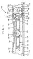
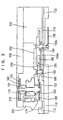
- a timepiece with spring winding state display 100 is provided with a main plate 102, a barrel bridge 104, a transmission wheel bridge 106 and a third bridge 108.
- a "movement” designates a mechanical body of a timepiece and a “complete” designates a complete entity of a timepiece containing a mechanical body, that is, a movement of a timepiece in a timepiece case.
- a "rear side” of the main plate 102 indicates a side of both faces of the main plate 102 proximate to glass of the timepiece case and a “surface side” of the main plate 102 indicates a side of the both faces of the main plate 102 remote from the glass of the timepiece case.
- a dial 110 is arranged on the rear side of the main plate 102 via a dial support ring 112.
- a support for dial side parts 114 is arranged between the main plate 102 and the dial 110.
- a winding stem 118 is integrated to the main plate 102.
- a barrel complete 120 is supported rotatably by the barrel bridge 104 and the main plate 102.
- the barrel complete 120 is provided with a mainspring 122, a barrel arbor 124, a barrel gear 126 and a barrel cover 128.
- the mainspring 122 constitutes a power source of a mechanical type timepiece.
- the barrel gear 126 is rotated in one direction and displays time information by hands via rotation of a front side gear train and a rear side gear train.
- the front side gear train and the rear side gear train are supported rotatably by the main plate 102, the third bridge 108 and a second bridge (not illustrated).
- a ratchet wheel 130 is integrated to a square shaft portion 124a of the barrel arbor 124 in the barrel complete 120.
- the ratchet wheel 130 is supported to rotate integrally with the barrel arbor 124 by a ratchet wheel screw 132.
- the ratchet wheel 130 can be rotated only in the same direction as the direction of rotation of the barrel complete 120.
- a click constituting a member for regulating rotation of the ratchet wheel is provided at the barrel bridge 104 for regulating the ratchet wheel 130 so as to rotate only in one direction.
- the ratchet wheel 130 is prevented from rotating in a direction opposed to the direction of rotation of the barrel complete 120 by the click.
- a hand winding mechanism (not illustrated) and/or an automatic winding mechanism (not illustrated) for winding up the mainspring 122 is attached to the transmission wheel bridge 106.
- the mainspring 122 can be wound up by rotating the ratchet wheel 130 by rotating the winding stem 118.
- An intermediate ratchet wheel 140 is supported rotatably to the third bridge 108 and the barrel bridge 104.
- the intermediate ratchet wheel 140 is in mesh with the ratchet wheel 130 and can be rotated by rotation of the ratchet wheel 130.
- a first sun wheel 150 is supported rotatably to the third bridge 108 and the main plate 102.
- the first sun wheel is provided with a first sun wheel gear 152 and a first sun wheel arbor 154.
- the first sun wheel arbor 154 includes a first axle portion 154a, a second axle portion 154b and a third axle portion 154c in a direction from the third bridge 108 to the main plate 102.
- the first sun gear 152 is disposed between the second axle portion 154b and the third axle portion 154c.
- a second sun wheel 160 is integrated rotatably to the first axle portion 154a of the first sun wheel arbor 154. That is, the center of rotation of the second sun wheel 160 is the same as the center of rotation of the first sun wheel 150.
- the second sun wheel 160 is provided with a second sun wheel gear 162 and a second sun wheel pinion 164.
- the second sun wheel gear 162 is in mesh with the intermediate ratchet wheel 140 and can be rotated by rotation of the intermediate ratchet 140.
- a planetary reduction wheel gear 170 is arranged rotatably relative to the second axle portion 154b of the first sun wheel arbor 154. That is, the center of rotation of the planetary reduction wheel gear 170 is the same as the center of rotation of the first sun wheel 150.
- the planetary reduction wheel gear 170 is in mesh with the barrel gear 126 and can be rotated by rotation of the barrel gear 126.
- a first planetary wheel 172 is arranged rotatably to the planetary reduction wheel gear 170 with the center of rotation disposed at a portion different from the center of rotation of the planetary reduction wheel gear 170.
- a second planetary wheel 174 is arranged rotatably to the planetary reduction wheel gear 170 with the center of rotation disposed at a portion different from the center of rotation of the planetary reduction wheel gear 170.
- the first planetary wheel 172 together with the second planetary wheel 174 constitute a planetary wheel 176 and both are fixed to each other such that the both are rotatably integrally relative to the planetary reduction wheel gear 170.
- first planetary wheel 172 is arranged to be able to rotate by being disposed on the surface side of the planetary reduction wheel gear 170 whereas the second planetary wheel 174 is arranged to be able to rotate by being disposed on the rear side of the planetary reduction wheel gear 170.
- the first planetary wheel 172 is in mesh with the second sun wheel pinion 164 and thus the first planetary wheel 172 can rotate while revolving around the second sun wheel pinion.
- the second planetary wheel 174 is in mesh with the first sun wheel gear 152 and thus the second planetary wheel 174 can rotate while revolving around the first sun wheel gear 152. Further, the first planetary wheel 172 and the second planetary wheel 174 are constituted to be able to rotate while revolving integrally.
- a sun wheel finger 180 is attached to the third axle portion 154c of the first sun wheel arbor 154.
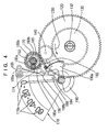
- the sun wheel finger 180 is provided with two of bridge portions 180a and 180b and two of feeding fingers 180c and 180d (refer to Fig. 4).
- the sun wheel finger 180 is attached to the third axle portion 154c such that the sun wheel finger 180 can be slipped by constant slip torque.
- the number of the bridge portions may be one or two or more.
- the number of the feeding fingers may be one or may be two or more. By determining the number of the feeding fingers, a speed reduction ratio of the gear train can be determined.
- an intermediate power reserve wheel 182 is supported rotatably to the main plate 102 and the support for dial side parts 116.
- the intermediate power reserve wheel 182 is provided with an intermediate power reserve wheel gear 184 and an intermediate power reserve wheel pinion 186.
- the two feeding fingers 180c and 180d are installed engageably with the intermediate power reserve wheel gear 184 so as to feed the intermediate power reserve wheel gear 184 intermittently.
- the intermediate power reserve wheel gear 184 is provided with 10 teeth, by one rotation of the sun wheel finger, the intermediate power reserve wheel gear 184 is fed by an amount of two teeth. Therefore, a speed reduction ratio of the portion is 1/5.
- a power reserve jumper 188 for regulating a position in the rotational direction of the intermediate power reserve wheel 182, is arranged between the main plate 102 and the support for dial side parts 116.
- the power reserve jumper 188 is provided with a power reserve jumper spring portion 188a and a power reserve jumper regulation portion 188b and the power reserve jumper regulation portion 188b regulates the two teeth of the intermediate power reserve wheel gear 184 (refer to Fig. 4).
- a power reserve wheel 190 is supported rotatably to the main plate 102 and the support for dial side parts 116.
- the power reserve wheel 190 is provided with a power reserve wheel gear 190a having an opening angle of substantially 60 degree and a power reserve wheel arbor 190b.
- the power reserve wheel gear 190a is in mesh with the intermediate power reserve wheel pinion 186 and can be rotated by rotation of the intermediate power reserve wheel pinion 186.
- Display signs 110a for displaying a spring winding state are installed on the dial 110.
- the display signs 110a include numerals of "0", “20", “40” and "60".
- the winding state of the spring can be displayed by indicating any of the display signs 110a by the power reserve hand 196.
- a rotational angle regulating member for regulating a range of a rotatable angle of the power reserve wheel 190 that is, a power reserve wheel positioning pin 198 is installed at the main plate 102.
- a power reserve wheel positioning pin 198 is installed at the main plate 102.
- the first sun wheel 150 is rotated in the counterclockwise direction, while the sun wheel finger 180 is rotated in the counterclockwise direction.
- the two feeding fingers 180c and 180d are operated alternately and cause to rotate intermittently the intermediate power reserve wheel gear 184 in the clockwise direction.
- the power reserve wheel 190 is rotated in the counterclockwise direction.
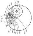
- the power reserve hand 196 is rotated in the counterclockwise direction and the state in which the power reserve hand 196 indicates in the display signs 110a is shifted from "0" (refer to Fig. 3 and Fig. 4) to "20" then to between “20” and “40” (refer to Fig. 7 and Fig. 8).
- the states shown in Fig. 7 and Fig. 8 are states in which the spring is "half wound”.
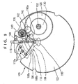
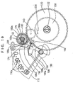
- the power reserve hand 196 is rotated further in the counterclockwise direction and shifted indicate "60" in the display signs 110a after indicating "40" in the display signs 110a (refer to Fig. 9 and Fig. 10). Shown in Fig. 9 and Fig. 10 is a state in which the spring is "fully wound".
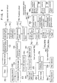
- the barrel gear 126 In reference to Fig. 6, in the state in which the spring is wound up, the barrel gear 126 is rotated and displays time. In this case, as shown in Fig. 4, the barrel gear 126 is rotated in the counterclockwise direction.
- the planetary reduction wheel gear 170 is rotated in the clockwise direction.
- Rotation of the second sun wheel 160 is regulated and accordingly, by rotation of the planetary reduction wheel gear 170, the first planetary wheel 172 is rotated while revolving around the second sun wheel pinion 164.
- the first planetary wheel 172 and the second planetary wheel 174 are integral with each other and accordingly, the second planetary wheel 174 is rotated while revolving around the first sun wheel gear 152.
- first planetary wheel 172 and the second planetary wheel 174 are rotated in the counterclockwise direction.
- Rotation of the first planetary wheel 172 and the second planetary wheel 174 is "planetary motion" in which the centers of rotation vary. Accordingly, by the constitution, there can be achieved a speed reduction ratio of a gear train larger than a speed reduction ratio of a normal gear train.
- the first sun wheel 150 is rotated in the clockwise direction
- the sun wheel finger 180 is rotated in the clockwise direction.
- two feeding fingers 180c and 180d are operated alternately and cause to rotate the intermediate power reserve wheel gear 184 intermittently in the counterclockwise direction.
- the power reserve wheel 190 is rotated in the clockwise direction.
- the power reserve hand 196 is rotated in the clockwise direction at a speed slower than a normal rotational speed of the gear train.
- the operation shifts from the state in which the power reserve hand 196 indicates "60" in the display signs 110a (refer to Fig. 9 and Fig. 10) to the state in which the power reserve hand 196 indicates an . intermediary between "40" and “20" in the display signs 110a (refer to Fig. 7 and Fig. 8) via the state in which the power reserve hand 196 indicates "40" in the display signs 110a.
- the state shown by Fig. 7 and Fig. 8 is a "half wound" state of the spring.
- the power reserve hand 196 is further rotated in the clockwise direction and shifts to the state in which the power reserve hand 196 indicates "0" in the display signs 110a (refer to Fig. 3 and Fig. 4) via the state in which the power reserve hand 196 indicates "20" in the display signs 110a.
- the state shown in Fig. 3 and Fig. 4 is a "winding released" state of the spring.
- the display signs 110a shown in the drawings of the embodiment of the invention designates operational duration time periods of the timepiece. For example, when the power reserve hand 196 indicates "20”, it indicates that the duration time period is 20 hours, and when the power reserve hand 196 indicates "40", it indicates that the duration time period is 40 hours. When the power reserve hand 196 indicates "60”, it indicates that the duration time period is 60 hours.
- the display signs 110a may be constituted such that "1" indicates a "fully wound” state of the spring, "1/2” indicates a “half wound” state of the spring and "0” indicates a "winding released” state of the spring. Further, the display signs 110a may be constituted such that “100 %” indicates the “fully wound” state of the spring, “50 %” indicates the “half wound” state of the spring and “0 %” indicates the “winding released” state of the spring. Alternatively, the display signs 110a may be constituted such that “black circle sign” indicates the "fully wound” state of the spring, a “semicircle sign” indicates the "half wound” state of the spring and a “white circle sign” indicates the "winding released” state of the spring.
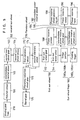
- rotation of the barrel gear 126 rotated by power of the spring is controlled by an adjusting device 240 and an escapement 242.
- the adjusting device 240 includes a balance wheel (not illustrated).
- the escapement 242 includes an anchor and an escapement wheel (both are not illustrated).
- a front side gear train 244 By rotation of the barrel gear, a front side gear train 244 is rotated.
- the front side gear train 244 includes a second wheel (or minute wheel), a third wheel, a fourth wheel (and/or second wheel) and so on.
- the front side gear train 244 is constituted such that a minute hand 246 attached to the second wheel (or minute wheel) constituting the front side gear train 244 displays "minute” and a second hand 248 attached to the fourth wheel (or second wheel) displays "second".
- the back side gear train 250 includes a date back side wheel, a cylinder wheel and so on.
- An hour hand 252 attached to the cylinder wheel displays "hour”.
- the timepiece with calendar may be constituted such that a calendar feeding mechanism 254 is operated based on rotation of the back side gear train 250.
- the calendar feeding mechanism 254 includes a date indicator, a date indicator claw, a day indicator claw, a date jumper, a day jumper and so on.
- the calendar feeding mechanism 254 is constituted such that by operating the calendar feeding mechanism 254, the date indicator displays "date” and a day indicator displays "day of week".
- timepiece of the invention is installed with a switching mechanism and a time setting mechanism for setting time of the timepiece and a sunday correcting mechanism for correcting the date indicator 256 and the day indicator 258 (none of them are illustrated).
- a complete of the timepiece with spring winding state display according to the invention includes a timepiece case 300 in which movement of the timepiece with spring winding state display of the invention is contained.
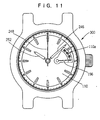
- Time of "hour”, "minute” and “second” is displayed by the hour hand 252, the minute hand 246 and the second hand 248.
- the display signs 110a installed on the dial indicate operable duration time period of the timepiece.
- the power reserve hand 196 indicates “0" in the display signs 110a.
- the state shown by Fig. 11 indicates the "winding released” state of the spring and indicates that the duration time period of the timepiece at the current time is 0 hour.
- the power reserve hand 196 is constituted to direct in "3 o'clock direction" of the timepiece in the "rewound” state of the spring.
- An angle of rotating the power reserve hand 96 from the "rewound” state of the spring is constituted to correspond to the duration time period of the timepiece.
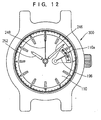
- the power reserve hand 196 indicates an intermediary between "20" and "40" of the display signs 110a.
- the state shown by Fig. 12 indicates the "half wound” state of the spring and the duration time period of the timepiece at the current time is about 30 hours.
- the angle of rotating the power reserve hand 196 from the state shown by Fig. 11 to the state shown by Fig. 12 is about 30 degrees which correspond to about 30 hours of the duration time period.
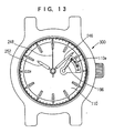
- the power reserve hand 196 indicates “60" in the display signs 110a.
- the state shown by Fig. 13 shows the "fully wound” state of the spring and the duration time period of the timepiece at the current time is about 60 hours.
- An angle of rotating the power reserve hand 196 from the state shown by Fig. 11 to the state shown by Fig. 13 is about 60 degrees which correspond to about 60 hours of the duration time period.
- the timepiece with spring winding state display according to the invention can display the duration time period of the timepiece in a manner which is very easy to understand.
- the speed reduction ratio from the barrel gear 126 to the power reserve wheel 190 is 7/360.
- timepiece with spring winding state display of the invention by changing the number of teeth of the gears mentioned above and/or the number of fingers of the sun wheel finger, content of display of the spring wound state can be changed. Further, by changing the above-described speed reduction ratio, the angle of rotation of the power reserve hand 196 based on rotation of the barrel gear 126 can be changed.
- the speed reduction ratio from the barrel gear 126 to the power reserve wheel 190 can be set to 7/720.
- the rotational angle of the power reserve wheel 190 corresponding to the shift from the winding released state to the fully wound state of the spring is about 30 degrees.
- the speed reduction ratio from the barrel gear 126 to the power reserve wheel 190 can be set to 7/240.
- the rotational angle of the power reserve wheel 190 in correspondence with from the winding released state to the fully wound state of the spring becomes about 90 degrees.
- the invention is constituted as mentioned above in the timepiece with spring winding state display and accordingly, there are achieved effects described below.
Landscapes
- Physics & Mathematics (AREA)
- General Physics & Mathematics (AREA)
- Measurement Of Unknown Time Intervals (AREA)
- Electromechanical Clocks (AREA)
Claims (7)
- Montre avec indicateur d'état remonté par ressort, comprenant une fonction d'affichage d'un état remonté d'un ressort qui constitue une source d'énergie d'une montre de type mécanique, ladite montre avec indicateur d'état remonté par ressort comprenant:un ensemble de barillet (120) comprenant un ressort-moteur (122), un arbre de barillet (124), un engrenage de barillet (126) et un couvercle de barillet (128), ledit engrenage de barillet (126) étant conçu de manière à pouvoir tourner dans une seule direction en détendant le ressort-moteur (122);une roue à rochet (130) supportée de manière à tourner intégralement avec l'arbre de barillet (124) et pouvant tourner dans une seule et même direction correspondant à la direction de rotation de l'engrenage de barillet (126);un élément de régulation (212) de la rotation de la roue à rochet pour réguler la rotation de la roue à rochet (130) dans une seule direction;une roue à rochet intermédiaire (140) installée d'une façon rotative par la rotation de la roue à rochet (130);un engrenage réducteur à roue planétaire (170) installé d'une façon rotative par la rotation de l'engrenage de barillet (126);une roue planétaire (176) installée d'une façon rotative sur l'engrenage réducteur à roue planétaire (170) avec un centre de rotation disposé à une partie différente par rapport à un centre de rotation de l'engrenage réducteur à roue planétaire (170) et comprenant une première roue planétaire (172) et une deuxième roue planétaire (174) pouvant tourner intégralement avec la roue planétaire (176);une première roue solaire (150) installée d'une façon rotative avec le centre de rotation de l'engrenage réducteur à roue planétaire (170) comme centre de rotation, comprenant un premier engrenage de roue solaire engrené avec la deuxième roue planétaire (174);une deuxième roue solaire (160) installée d'une façon rotative avec le centre de rotation de la première roue solaire (150) comme centre de rotation, et comprenant un deuxième engrenage de roue solaire (162) engrené avec la roue à rochet intermédiaire (140) et un deuxième pignon de roue solaire (164) engrené avec la première roue planétaire (172); etun élément d'affichage d'état remonté par ressort (196) pour afficher un état remonté du ressort, caractérisée en ce que:un doigt (180) de la roue solaire est attaché à la première roue solaire (150), le doigt de la roue solaire comprenant un ou plusieurs doigts d'avancement (180c, 180d);une roue de réserve d'énergie intermédiaire (182) est installée et peut être mise en rotation d'une façon intermittente par les doigts d'avancement (180c, 180d);un répartiteur de réserve d'énergie (188) est prévu pour régler une position dans une direction rotative de la roue de réserve d'énergie intermédiaire (182); etl'élément d'affichage de l'état remonté par ressort (196) est conçu de manière à afficher l'état remonté du ressort sur la base de la rotation de la roue de réserve d'énergie intermédiaire (182).
- Montre avec indicateur d'état remonté par ressort selon la revendication 1, caractérisée en ce qu'elle comprend en outre:une roue de réserve d'énergie (190) mise en rotation sur la base de la rotation de la roue de réserve d'énergie intermédiaire (182); etune aiguille de réserve d'énergie (196) attachée à la roue de réserve d'énergie (190).
- Montre avec indicateur d'état remonté par ressort selon la revendication 1 ou la revendication 2, caractérisée en ce que la première roue solaire (150) comprend le premier engrenage de roue solaire (152) et un premier arbre de roue solaire (154);
la deuxième roue solaire (160) est intégrée d'une façon rotative au premier arbre de roue solaire (154); et
le doigt (180) de la roue solaire est attaché d'une façon glissante au premier arbre de roue solaire (154). - Montre avec indicateur d'état remonté par ressort selon la revendication 3, caractérisée en ce que l'engrenage réducteur à roue planétaire (170) est intégré d'une façon rotative au premier arbre de roue solaire (154).
- Montre avec indicateur d'état remonté par ressort selon l'une quelconque des revendications précédentes, caractérisée en ce que l'élément d'affichage de l'état remonté par ressort (196) est conçu de manière à tourner d'une façon intermittente dans une première direction sur la base d'une sortie en provenance du doigt (180) de la roue solaire, et à tourner dans une deuxième direction opposée à la première direction sous l'action d'un mécanisme d'engrenage planétaire comprenant les première et deuxième roues solaires (150, 160), l'engrenage réducteur à roue planétaire (170) et la roue planétaire (176) sur la base de la rotation de l'engrenage de barillet (126).
- Montre avec indicateur d'état remonté par ressort selon la revendication 5, caractérisée par un élément de régulation (188) de la rotation de la roue de réserve d'énergie intermédiaire destiné à réguler la rotation de la roue de réserve d'énergie intermédiaire (182).
- Montre avec indicateur d'état remonté par ressort selon la revendication 6, caractérisée en ce que les doigts d'avancement (180c, 180d) sont installé de manière à être capables de glisser par rapport aux première et deuxième roues solaires (150, 160), à l'engrenage réducteur à roue planétaire (170) et à la roue planétaire (176).
Applications Claiming Priority (3)
| Application Number | Priority Date | Filing Date | Title |
|---|---|---|---|
| JP35361997 | 1997-12-22 | ||
| JP9353619A JPH11183642A (ja) | 1997-12-22 | 1997-12-22 | ぜんまい巻き状態表示装置付き時計 |
| PCT/JP1998/005788 WO1999032942A1 (fr) | 1997-12-22 | 1998-12-22 | Montre avec indicateur d'etat remonte par ressort-moteur |
Publications (3)
| Publication Number | Publication Date |
|---|---|
| EP0962839A1 EP0962839A1 (fr) | 1999-12-08 |
| EP0962839A4 EP0962839A4 (fr) | 2000-03-15 |
| EP0962839B1 true EP0962839B1 (fr) | 2004-09-15 |
Family
ID=18432079
Family Applications (1)
| Application Number | Title | Priority Date | Filing Date |
|---|---|---|---|
| EP98961459A Expired - Lifetime EP0962839B1 (fr) | 1997-12-22 | 1998-12-22 | Montre avec indicateur d'etat remonte par ressort-moteur |
Country Status (7)
| Country | Link |
|---|---|
| US (1) | US6166999A (fr) |
| EP (1) | EP0962839B1 (fr) |
| JP (1) | JPH11183642A (fr) |
| CN (1) | CN1119719C (fr) |
| DE (1) | DE69826248T2 (fr) |
| TW (1) | TW371728B (fr) |
| WO (1) | WO1999032942A1 (fr) |
Families Citing this family (16)
| Publication number | Priority date | Publication date | Assignee | Title |
|---|---|---|---|---|
| EP1074897B1 (fr) * | 1999-08-04 | 2009-04-15 | Frédéric Piguet S.A. | Dispositif indicateur de réserve de marche pour pièce d'horlogerie |
| EP1139182B1 (fr) * | 2000-03-27 | 2007-10-03 | Vaucher Manufacture Fleurier SA | Mécanisme indicateur de réserve de marche et montre munie d'un tel mécanisme |
| ATE390654T1 (de) * | 2002-02-01 | 2008-04-15 | Tag Heuer Sa | Vorrichtung mit uhrwerk und chronographenmodul |
| JP2003227883A (ja) * | 2002-02-04 | 2003-08-15 | Seiko Instruments Inc | ぜんまいを動力とする時計 |
| JP4475630B2 (ja) | 2004-01-27 | 2010-06-09 | セイコーインスツル株式会社 | 変形セグメント歯車を含むぜんまい巻き状態表示装置付き時計 |
| EP1562086B1 (fr) * | 2004-02-04 | 2011-11-23 | Vaucher Manufacture Fleurier S.A. | Mécanisme indicateur de réserve de marche |
| JP4619818B2 (ja) * | 2005-02-22 | 2011-01-26 | セイコーインスツル株式会社 | パワーリザーブ表示機構及びこれを備えた機械式時計 |
| JP4836823B2 (ja) * | 2007-02-09 | 2011-12-14 | セイコーインスツル株式会社 | 時計の巻印残量表示機構及び巻印残量表示機構付時計 |
| EP1970778B1 (fr) * | 2007-03-13 | 2009-09-16 | Montres Breguet S.A. | Pièce d'horlogerie comprenant un dispositif indicateur de réserve de marche |
| EP2360535B1 (fr) * | 2010-02-24 | 2012-12-05 | Blancpain S.A. | Masse oscillante pour montre à remontage automatique, comportant un dispositif indicateur de la réserve de marche intégré dans ladite masse oscillante |
| JP5320368B2 (ja) * | 2010-10-01 | 2013-10-23 | セイコークロック株式会社 | 時計 |
| CH707136B1 (fr) * | 2012-10-30 | 2016-12-30 | Parmigiani Fleurier S A | Pièce d'horlogerie destinée à indiquer la réserve de marche. |
| JP6738166B2 (ja) * | 2016-03-09 | 2020-08-12 | セイコーインスツル株式会社 | パワーリザーブ機構、ムーブメントおよび時計 |
| EP3605243A1 (fr) * | 2018-07-31 | 2020-02-05 | Montres Breguet S.A. | Mecanisme d'affichage d'horlogerie a geometrie variable avec aiguille elastique |
| EP3627233B1 (fr) * | 2018-09-19 | 2022-03-30 | ETA SA Manufacture Horlogère Suisse | Mecanisme indicateur de reserve de marche d'horlogerie |
| CN110658713B (zh) * | 2019-09-17 | 2021-04-09 | 珠海罗西尼表业有限公司 | 机械表满条率的检测方法 |
Family Cites Families (10)
| Publication number | Priority date | Publication date | Assignee | Title |
|---|---|---|---|---|
| FR261346A (fr) * | 1900-01-01 | |||
| US588373A (en) * | 1897-08-17 | antoine | ||
| US1191525A (en) * | 1913-03-01 | 1916-07-18 | Joseph Mazer | Winding-indicator. |
| CH289108A (de) * | 1951-03-14 | 1953-02-28 | Felsa Ag | Uhrwerk mit einem mit dem Federhaus und mit der Federhauswelle in Antriebsverbindung stehenden Differentialgetriebe. |
| JPS4324870B1 (fr) * | 1965-04-06 | 1968-10-26 | ||
| CH643701B (fr) * | 1980-10-24 | Ebauchesfabrik Eta Ag | Montre a remontage automatique. | |
| CH678474GA3 (en) * | 1990-02-27 | 1991-09-30 | Watch movement with winding indication - has satellite carrier fixed on hub of central coaxial bodies which turn in opposite directions when winding balances unwind | |
| JP2757147B2 (ja) * | 1995-07-07 | 1998-05-25 | セイコーインスツルメンツ株式会社 | ぜんまい動力蓄積量表示付き機械式時計 |
| CH688879B5 (fr) * | 1995-08-10 | 1998-11-13 | Asulab Sa | Pièce d'horlogerie avec indication de la réserve de marche. |
| CH690973A5 (fr) * | 1996-12-19 | 2001-03-15 | Asulab Sa | Pièce d'horlogerie dont le mécanisme est entraîné par des moyens mécaniques et comprenant un dispositif d'indication de réserve de marche. |
-
1997
- 1997-12-22 JP JP9353619A patent/JPH11183642A/ja active Pending
-
1998
- 1998-12-22 CN CN98804159A patent/CN1119719C/zh not_active Expired - Fee Related
- 1998-12-22 DE DE69826248T patent/DE69826248T2/de not_active Expired - Fee Related
- 1998-12-22 WO PCT/JP1998/005788 patent/WO1999032942A1/fr not_active Ceased
- 1998-12-22 US US09/367,882 patent/US6166999A/en not_active Expired - Lifetime
- 1998-12-22 TW TW087121415A patent/TW371728B/zh active
- 1998-12-22 EP EP98961459A patent/EP0962839B1/fr not_active Expired - Lifetime
Also Published As
| Publication number | Publication date |
|---|---|
| EP0962839A1 (fr) | 1999-12-08 |
| CN1119719C (zh) | 2003-08-27 |
| CN1252139A (zh) | 2000-05-03 |
| JPH11183642A (ja) | 1999-07-09 |
| EP0962839A4 (fr) | 2000-03-15 |
| WO1999032942A1 (fr) | 1999-07-01 |
| TW371728B (en) | 1999-10-11 |
| DE69826248T2 (de) | 2005-01-27 |
| HK1026483A1 (en) | 2000-12-15 |
| US6166999A (en) | 2000-12-26 |
| DE69826248D1 (de) | 2004-10-21 |
Similar Documents
| Publication | Publication Date | Title |
|---|---|---|
| US6166999A (en) | Clock with a mainspring wound state indicator | |
| JP3140700B2 (ja) | 多機能時計 | |
| US6295249B1 (en) | Display correction device and timepiece equipped with display correction device | |
| US20060140057A1 (en) | Multifunction timepiece capable of constituting plural fan shape moving hand train wheel layouts | |
| EP1826639A1 (fr) | Pièce d'horlogerie avec temps de fonctionnement cumulatif | |
| US7300200B2 (en) | Timepiece having mainspring winding state display apparatus including deformed segment gear | |
| CN110941173B (zh) | 机芯以及电子钟表 | |
| US7275860B2 (en) | Display correcting mechanism and timepiece having display correcting mechanism | |
| EP1898277B1 (fr) | Appareil horaire multifonction capable de réaliser une pluralité d'agencements de mouvement | |
| JP2017161327A (ja) | パワーリザーブ機構、ムーブメントおよび時計 | |
| US4692031A (en) | Moon phase display clock | |
| US20040130972A1 (en) | Self-winding timepiece having train wheel setting apparatus | |
| EP0547250B1 (fr) | Montre-reveil silencieuse | |
| CN100594451C (zh) | 包括多个类型的指针操作轮系的多功能时计 | |
| US7532546B2 (en) | Timepiece with calendar mechanism having date indicators for indicating date | |
| US20070047390A1 (en) | Timepiece with calendar mechanism indicating date by plurality of date indicators | |
| US20070097794A1 (en) | Timepiece with a fan-shaped hand motion display mechanism | |
| CN112666817A (zh) | 钟表 | |
| US6222796B1 (en) | Astrological watch | |
| JP2612234B2 (ja) | 回転式表示手段を有する時計 | |
| JP7611334B2 (ja) | 年周期の複数期間を表示する機構、時計ムーブメント及び時計 | |
| JP2615840B2 (ja) | 指針式世界時計 | |
| JP2005214656A (ja) | リンクを含むぜんまい巻き状態表示装置付き時計 | |
| JPH0648459Y2 (ja) | 時計における歯車の回転位置規制構造 | |
| JPS6252834B2 (fr) |
Legal Events
| Date | Code | Title | Description |
|---|---|---|---|
| PUAI | Public reference made under article 153(3) epc to a published international application that has entered the european phase |
Free format text: ORIGINAL CODE: 0009012 |
|
| AK | Designated contracting states |
Kind code of ref document: A1 Designated state(s): CH DE FR GB LI |
|
| 17P | Request for examination filed |
Effective date: 19991130 |
|
| A4 | Supplementary search report drawn up and despatched |
Effective date: 20000201 |
|
| AK | Designated contracting states |
Kind code of ref document: A4 Designated state(s): CH DE FR GB LI |
|
| 17Q | First examination report despatched |
Effective date: 20030711 |
|
| GRAP | Despatch of communication of intention to grant a patent |
Free format text: ORIGINAL CODE: EPIDOSNIGR1 |
|
| GRAS | Grant fee paid |
Free format text: ORIGINAL CODE: EPIDOSNIGR3 |
|
| GRAA | (expected) grant |
Free format text: ORIGINAL CODE: 0009210 |
|
| AK | Designated contracting states |
Kind code of ref document: B1 Designated state(s): CH DE FR GB LI |
|
| REG | Reference to a national code |
Ref country code: GB Ref legal event code: FG4D Ref country code: CH Ref legal event code: EP |
|
| REF | Corresponds to: |
Ref document number: 69826248 Country of ref document: DE Date of ref document: 20041021 Kind code of ref document: P |
|
| REG | Reference to a national code |
Ref country code: CH Ref legal event code: NV Representative=s name: PATENTANWAELTE SCHAAD, BALASS, MENZL & PARTNER AG |
|
| PG25 | Lapsed in a contracting state [announced via postgrant information from national office to epo] |
Ref country code: GB Free format text: LAPSE BECAUSE OF NON-PAYMENT OF DUE FEES Effective date: 20041222 |
|
| ET | Fr: translation filed | ||
| PLBE | No opposition filed within time limit |
Free format text: ORIGINAL CODE: 0009261 |
|
| STAA | Information on the status of an ep patent application or granted ep patent |
Free format text: STATUS: NO OPPOSITION FILED WITHIN TIME LIMIT |
|
| GBPC | Gb: european patent ceased through non-payment of renewal fee |
Effective date: 20041222 |
|
| 26N | No opposition filed |
Effective date: 20050616 |
|
| PGFP | Annual fee paid to national office [announced via postgrant information from national office to epo] |
Ref country code: FR Payment date: 20051208 Year of fee payment: 8 |
|
| PGFP | Annual fee paid to national office [announced via postgrant information from national office to epo] |
Ref country code: DE Payment date: 20061214 Year of fee payment: 9 |
|
| PGFP | Annual fee paid to national office [announced via postgrant information from national office to epo] |
Ref country code: CH Payment date: 20061227 Year of fee payment: 9 |
|
| REG | Reference to a national code |
Ref country code: FR Ref legal event code: ST Effective date: 20070831 |
|
| PG25 | Lapsed in a contracting state [announced via postgrant information from national office to epo] |
Ref country code: FR Free format text: LAPSE BECAUSE OF NON-PAYMENT OF DUE FEES Effective date: 20070102 |
|
| REG | Reference to a national code |
Ref country code: CH Ref legal event code: PL |
|
| PG25 | Lapsed in a contracting state [announced via postgrant information from national office to epo] |
Ref country code: LI Free format text: LAPSE BECAUSE OF NON-PAYMENT OF DUE FEES Effective date: 20071231 Ref country code: DE Free format text: LAPSE BECAUSE OF NON-PAYMENT OF DUE FEES Effective date: 20080701 Ref country code: CH Free format text: LAPSE BECAUSE OF NON-PAYMENT OF DUE FEES Effective date: 20071231 |