EP0962849A2 - Dispositif anti-retour pour le levier d'un appareil de commande à distance - Google Patents
Dispositif anti-retour pour le levier d'un appareil de commande à distance Download PDFInfo
- Publication number
- EP0962849A2 EP0962849A2 EP99200545A EP99200545A EP0962849A2 EP 0962849 A2 EP0962849 A2 EP 0962849A2 EP 99200545 A EP99200545 A EP 99200545A EP 99200545 A EP99200545 A EP 99200545A EP 0962849 A2 EP0962849 A2 EP 0962849A2
- Authority
- EP
- European Patent Office
- Prior art keywords
- lever
- box
- central position
- knob
- pin
- Prior art date
- Legal status (The legal status is an assumption and is not a legal conclusion. Google has not performed a legal analysis and makes no representation as to the accuracy of the status listed.)
- Withdrawn
Links
- 230000002452 interceptive effect Effects 0.000 claims abstract description 4
- 230000033001 locomotion Effects 0.000 description 4
- 230000005540 biological transmission Effects 0.000 description 2
- 230000010355 oscillation Effects 0.000 description 2
- 230000006355 external stress Effects 0.000 description 1
- 230000003993 interaction Effects 0.000 description 1
Images


Classifications
-
- G—PHYSICS
- G05—CONTROLLING; REGULATING
- G05G—CONTROL DEVICES OR SYSTEMS INSOFAR AS CHARACTERISED BY MECHANICAL FEATURES ONLY
- G05G5/00—Means for preventing, limiting or returning the movements of parts of a control mechanism, e.g. locking controlling member
- G05G5/06—Means for preventing, limiting or returning the movements of parts of a control mechanism, e.g. locking controlling member for holding members in one or a limited number of definite positions only
- G05G5/08—Interlocking of members, e.g. locking member in a particular position before or during the movement of another member
-
- G—PHYSICS
- G05—CONTROLLING; REGULATING
- G05G—CONTROL DEVICES OR SYSTEMS INSOFAR AS CHARACTERISED BY MECHANICAL FEATURES ONLY
- G05G5/00—Means for preventing, limiting or returning the movements of parts of a control mechanism, e.g. locking controlling member
- G05G5/02—Means preventing undesired movements of a controlling member which can be moved in two or more separate steps or ways, e.g. restricting to a stepwise movement or to a particular sequence of movements
Definitions
- the present invention refers to an anti-reverse device for the lever in a remote control apparatus.
- lever devices for operating two rigid tension bars or alternatively a single flexible or non flexible cable, and these devices are commonly known as "push-pull".
- the devices are placed in a box, where on one side, a control lever extends outwards and from, the other side, a remote transmission cable extends. Naturally, a transmission cable reaction sheath is joined to the box.
- the remote control device box has a knob or a similar element that interacts between the lever and the box so as to cause a required reciprocal positioning which is more or less firm, avoiding possible reverse motions.
- This positioning is necessary since it must be certain that the control position is not changed in the case Of vibrations or, on the other hand, that it can be changed when necessary and required by the user.
- knobs have been made which are connected to the box, and which work by rotation in order to move locking elements which can be freely unlocked between an area of the lever and an area off the box.
- a purpose of the present invention is therefore to realise an anti-reverse device for the lever in a remote control apparatus that will avoid these technical problems relative to the unstable and firm positioning shown by the known devices.
- Another purpose is to realise an anti-reverse device for the lever in a remote control apparatus that allows, in any case, a safe positioning, and suitable to stand external stresses even when accidental, like in the case of vibrations.
- an anti-reverse device for the lever in a remote control apparatus placed in a box by means of trailing cable, which can be connected to an outer structure of a driving machine, wherein said box has a first opening for the passage of an operating lever for a single cable core movable within a reaction sheath, connected to said box, said lever being able to oscillate around a pivot, and locking means of the lever position which can be easily unlocked are provided outside said box, characterised in that said locking means comprise an external knob, to which an elastically flexible ball is joined and said bail is snap inserted into cavities provided on said box, and a shaped plate, placed at the end of a rotation shaft of said knob, selectively interactive with a pin projecting from said lever.
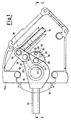
- a box 11a, 11b is shown in which a remote control apparatus driven by means of a single trailing cable is placed.
- box-shaped element or box realised for example in two coupled pieces 11a and 11b, which can be connected to a driving machine outer structure.
- box 11a, 11b there is a first opening 12 wherefrom an operating lever 13 extends for a single cable core, which is shown as a curved end in the shape of a hook 14 and, as known, which is movable within a reaction sheath (not shown) connected to the box.
- the operating lever 13 can oscillate around a pivot 16, which ends can be placed in two opposite seats 15, which have bushings or similar supports 17, provided inside the two opposite halves of the box 11, 11b.
- the lever 13, in particular, can oscillate around the pivot 16 between a central position and two positions placed on opposite sides with respects to said central position.
- the lever 13 has an extension 18 in a hole 19 where the hooked end part of the cable 14 is placed.
- An enlargement 20 is also positioned or obtained in one half of the box 11a underneath the curved hook shaped end 14.
- the enlargement 20, which has various slanting and shapes in height, has, at least in part, a curved shape that follows the oscillations of hole 19 of the operating lever 13. This configuration ensures the engagement of the curved end 14 inside the hole 19 for small oscillations of the lever.
- An anti-reverse device for the lever of a remote control apparatus is placed on the half box 11a, according to the present invention.
- This device comprises a knob 21, locked, by means of a radial dowel 22, on a first shaft end 23 placed in a hole 25 of the knob 21 and aligned to a hole 24 of the half box 11a.
- the knob 21 has a through hole 26, coaxial to hole 25, in which a spring 28, held by means of a another dowel 27, acts upon a small ball 29.
- An outer structure 30 of the half box 11a has, placed on an arc portion of a circle, a series of three rounded cavities 31, 32 and 33 to partially receive said ball 29. In this way, the ball 29, elastically movable by means of the spring 28, is snap inserted into the cavities.
- the lever position 13 locking means which can be easily unlocked, have been realised on the outer structure off box 11a, 11b, which are activated through the position of the knob 21.
- the shaft 23 has an eccentric integral plate 50, shaped to be able to interact with the extension 18 of the lever 13 that has, in a lowered area 41, a projecting pin 34.
- This plate 50 having a shape of a sector with rounded edges at about 90°, has tooth portions at different heights. Equally, there could be just one tooth element that extends for the entire sector with a central cavity indicated by 38, which is suitable to receive the projecting pin 34.
- a tooth element with several portions is provided. There is, in fact, a first maximum height tooth portion 35, that occupies a good part of the centre and one side of the sector, a second intermediate height tooth portion 36 towards the remaining sector end and a third minimum height tooth portion 37. This last portion 37 is placed behind the other two, in the area where the sector is attached to the shaft 23 and is suitable to receive the pin 34.
- the first two tooth portions 35 and 36 have a rounded cavity 38 on the side facing the centre of the plate, said cavity is in relation with the third tooth portion 37, wherein the projecting pin 34 can be received, only when the central locking position of the lever 13 is in place.
- the ball 29 is housed inside the central cavity 32 of the outer surface 30 of the half box 11a, as shown in figures 1-3.
- the lever 13 when it is activated through the interaction of the pin 34 with one of the bevelled slanting surfaces 35' of the first tooth portion 35, returns the shaped plate 50 to its initial position rotated towards the side.
- the knob 21 is rotated in a way to move the second intermediate height tooth portion 36 away from the central position. If the knob accidentally rotates taking the sector plate 50 with it and returning said plate towards the central position, because the lever 13 has been turned back, the sector 50 is returned to its initial rotated position. This happens because the projecting pin 34 of the lever 13 abuts on one of the end surfaces 36' of the second tooth portion 36.
- This particular device solves the problems of the presently known devices.
Landscapes
- Physics & Mathematics (AREA)
- General Physics & Mathematics (AREA)
- Engineering & Computer Science (AREA)
- Automation & Control Theory (AREA)
- Mechanical Control Devices (AREA)
- Rotary Switch, Piano Key Switch, And Lever Switch (AREA)
Applications Claiming Priority (2)
| Application Number | Priority Date | Filing Date | Title |
|---|---|---|---|
| ITMI981254 | 1998-06-04 | ||
| IT98MI001254A ITMI981254A1 (it) | 1998-06-04 | 1998-06-04 | Dispositivo antiinversione per la leva in un comando a distanza |
Publications (2)
| Publication Number | Publication Date |
|---|---|
| EP0962849A2 true EP0962849A2 (fr) | 1999-12-08 |
| EP0962849A3 EP0962849A3 (fr) | 2001-04-25 |
Family
ID=11380173
Family Applications (1)
| Application Number | Title | Priority Date | Filing Date |
|---|---|---|---|
| EP99200545A Withdrawn EP0962849A3 (fr) | 1998-06-04 | 1999-02-25 | Dispositif anti-retour pour le levier d'un appareil de commande à distance |
Country Status (2)
| Country | Link |
|---|---|
| EP (1) | EP0962849A3 (fr) |
| IT (1) | ITMI981254A1 (fr) |
Family Cites Families (3)
| Publication number | Priority date | Publication date | Assignee | Title |
|---|---|---|---|---|
| US3470771A (en) * | 1968-01-30 | 1969-10-07 | North American Rockwell | Transmission and auxiliary throttle control having a safety interlock |
| GB8707998D0 (en) * | 1987-04-03 | 1987-05-07 | Morse Controls | Remote control mechanisms |
| DE4406236A1 (de) * | 1994-02-25 | 1995-08-31 | Kloeckner Moeller Gmbh | Verriegelungsvorrichtung |
-
1998
- 1998-06-04 IT IT98MI001254A patent/ITMI981254A1/it unknown
-
1999
- 1999-02-25 EP EP99200545A patent/EP0962849A3/fr not_active Withdrawn
Non-Patent Citations (1)
| Title |
|---|
| None |
Also Published As
| Publication number | Publication date |
|---|---|
| ITMI981254A1 (it) | 1999-12-04 |
| EP0962849A3 (fr) | 2001-04-25 |
Similar Documents
| Publication | Publication Date | Title |
|---|---|---|
| EP2599943B1 (fr) | Dispositif de verrouillage électronique de portière pour coupler facilement un embrayage | |
| EP1746225A2 (fr) | Dispositif de verrouillage | |
| EP0064942B1 (fr) | Embrayage centrifuge | |
| CA2144132A1 (fr) | Verrou entraine par un moteur electrique et/ou une cle mecanique | |
| US5243157A (en) | Lockable handle | |
| KR200452407Y1 (ko) | 패닉기능을 갖는 기어박스 | |
| EP0962849A2 (fr) | Dispositif anti-retour pour le levier d'un appareil de commande à distance | |
| EP1741592B1 (fr) | Dispositif de levier de changement de vitesse | |
| CN115012798B (zh) | 百叶窗控制器 | |
| US20220259892A1 (en) | Locking device | |
| KR950019236A (ko) | 선풍기 | |
| EP3626991A1 (fr) | Embrayage automatique bidirectionnel | |
| KR101815962B1 (ko) | 푸쉬-풀 방식의 디지털 도어락 | |
| KR101261909B1 (ko) | 클러치 액츄에이터의 역회전 방지 구조 | |
| JP3113754U (ja) | 回転リング伝動装置用切換装置 | |
| JP4722291B2 (ja) | 2つの回転運動可能な軸端の連結のための継手 | |
| JPH09209627A (ja) | ドアロックアクチュエータ | |
| AU2014216016B2 (en) | Electronic door lock device for connecting clutch easily | |
| KR200301752Y1 (ko) | 도어록의 해정장치 | |
| CN216866306U (zh) | 一种洗衣机门锁 | |
| WO1997012161A1 (fr) | Ameliorations apportees a des mecanismes de fermeture de portes | |
| EP0939237A2 (fr) | Dispositif antirotation à verrouillage rapide pour appareil de télécommande | |
| KR200180493Y1 (ko) | 원통형 레버록의 안전장치 | |
| JP2010113941A (ja) | 遠隔操作用スイッチ操作体 | |
| KR20020042367A (ko) | 자동차의 도어록어셈블리 |
Legal Events
| Date | Code | Title | Description |
|---|---|---|---|
| PUAI | Public reference made under article 153(3) epc to a published international application that has entered the european phase |
Free format text: ORIGINAL CODE: 0009012 |
|
| AK | Designated contracting states |
Kind code of ref document: A2 Designated state(s): AT BE CH CY DE DK ES FI FR GB GR IE IT LI LU MC NL PT SE |
|
| AX | Request for extension of the european patent |
Free format text: AL;LT;LV;MK;RO;SI |
|
| PUAL | Search report despatched |
Free format text: ORIGINAL CODE: 0009013 |
|
| AK | Designated contracting states |
Kind code of ref document: A3 Designated state(s): AT BE CH CY DE DK ES FI FR GB GR IE IT LI LU MC NL PT SE |
|
| AX | Request for extension of the european patent |
Free format text: AL;LT;LV;MK;RO;SI |
|
| RIC1 | Information provided on ipc code assigned before grant |
Free format text: 7G 05G 5/00 A, 7G 05G 5/02 B, 7G 05G 5/08 B |
|
| AKX | Designation fees paid | ||
| REG | Reference to a national code |
Ref country code: DE Ref legal event code: 8566 |
|
| STAA | Information on the status of an ep patent application or granted ep patent |
Free format text: STATUS: THE APPLICATION IS DEEMED TO BE WITHDRAWN |
|
| 18D | Application deemed to be withdrawn |
Effective date: 20011026 |