EP0963002A1 - Glasscheibenantennensystem für Motorfahrzeuge - Google Patents
Glasscheibenantennensystem für Motorfahrzeuge Download PDFInfo
- Publication number
- EP0963002A1 EP0963002A1 EP99304324A EP99304324A EP0963002A1 EP 0963002 A1 EP0963002 A1 EP 0963002A1 EP 99304324 A EP99304324 A EP 99304324A EP 99304324 A EP99304324 A EP 99304324A EP 0963002 A1 EP0963002 A1 EP 0963002A1
- Authority
- EP
- European Patent Office
- Prior art keywords
- antenna
- antenna pattern
- motor vehicles
- patterns
- received
- Prior art date
- Legal status (The legal status is an assumption and is not a legal conclusion. Google has not performed a legal analysis and makes no representation as to the accuracy of the status listed.)
- Granted
Links
- 239000011521 glass Substances 0.000 title claims abstract description 29
- 230000035945 sensitivity Effects 0.000 abstract description 17
- 230000015572 biosynthetic process Effects 0.000 description 7
- 238000003786 synthesis reaction Methods 0.000 description 7
- 239000003990 capacitor Substances 0.000 description 4
- 238000013016 damping Methods 0.000 description 3
- 230000008878 coupling Effects 0.000 description 1
- 238000010168 coupling process Methods 0.000 description 1
- 238000005859 coupling reaction Methods 0.000 description 1
- 230000003247 decreasing effect Effects 0.000 description 1
- 230000000593 degrading effect Effects 0.000 description 1
- 239000005357 flat glass Substances 0.000 description 1
- 230000004048 modification Effects 0.000 description 1
- 238000012986 modification Methods 0.000 description 1
- 230000002093 peripheral effect Effects 0.000 description 1
- 230000002194 synthesizing effect Effects 0.000 description 1
Images


Classifications
-
- H—ELECTRICITY
- H01—ELECTRIC ELEMENTS
- H01Q—ANTENNAS, i.e. RADIO AERIALS
- H01Q1/00—Details of, or arrangements associated with, antennas
- H01Q1/12—Supports; Mounting means
- H01Q1/1271—Supports; Mounting means for mounting on windscreens
Definitions
- the present invention relates to a glass window antenna system for motor vehicles, particularly to increase the sensitivity for an AM band in the system which may receive both AM and FM bands.
- a glass window antenna system for motor vehicles which may receive both AM and FM bands
- a glass window antenna system in which antenna patterns are provided in proximity to a defogging device (hereinafter referred to as "defogger") so as to be capacitively coupled thereto.
- the defogger is consisted of heater wires and bus-bars provided on a rear window, the bus-bars applying a current to the heater wires.
- a choke coil is provided between the bus-bars and a DC power supply for the defogger.
- This type of conventional glass window antenna system has various problems such as the decrease of S/N ratio due to an engine noise for the defogger, the decrease of a sensitivity for a FM band due to an interference between the antenna patterns and the defogger, and the difficulty for making the antenna system compact due to the big and heavy choke coil.
- a glass window antenna system for motor vehicles which may receive both AM and FM bands in Japanese laid-open publication No. 9-181513.
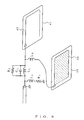
- the antenna system comprises a glass plate of a rear window 1, a circuit mounting component 2, an antenna terminal/power supply terminal box 3, a junction box for a second AM antenna 4, a bus-bar 5, a FM antenna 6, a first AM antenna 7, a second AM antenna 8, a receiver 9, a heater wire 10, a flexible circuit board 11, and a DC power supply 12.
- Fig.2 shows a circuitry of the circuit mounting component 2.
- the circuitry comprises an AM resonance inductor 13, a damping resistor 14, a high frequency inductor 15 to compensate the decrease of an impedance in an AM band wherein the AM resonance inductor 13 becomes capacitive, a damping resistor 16, an AM resonance inductor 17, a coupling capacitor 18, a connection line 19 on the flexible circuit board 11.
- the first and second AM antennas 7, 8 provided on the glass plate 1 are connected together by the line 19 on the flexible circuit board 11.
- a series resonance is caused by the stray capacitance for the AM antennas 7, 8 and the inductance of the AM resonance inductor 13
- a parallel resonance is caused by the stray capacitance for AM antennas 7, 8 and the inductance of the AM resonance inductor 17.
- the conventional glass window antenna system disclosed in the Japanese laid-open publication No. 9-181513 has utilized both series and parallel resonances for receiving an AM band, so that it is difficult to set appropriately the inductance values of the resonance inductors 15, 17 in order to establish both series and parallel resonance conditions, respectively.
- the object of the present invention is to increase the sensitivity for an AM band in a glass window antenna system for motor vehicles by means of an extremely simple structure in a limited space other than the defogger on a rear window.
- Another object of the present invention is to increase the sensitivity for an AM band in a very simple structure by using not only a rear window but also a side window(s).
- a glass window antenna system for motor vehicles comprises one AM/FM antenna pattern provided on a rear window which mainly receives a FM band while maintaining an AM receiving characteristic, and one or more AM antenna patterns provided on the rear window.
- the total occupied area of both the AM/FM antenna pattern and the AM antenna patterns has at least 0.2m 2 .
- An AM voltage received by the AM/FM antenna pattern and an AM voltage received by the AM antenna patterns are synthesized by superimposing the AM received voltage of the AM antenna patterns to the AM received voltage of the AM/FM antenna pattern through a low-pass filter.
- the receiving sensitivity may be increased by means of a very simple structure, because at least one AM/FM antenna pattern and one or more AM antenna patterns are provided to synthesize the AM voltages received by these antenna patterns.
- the sensitivity may be further enhanced by increasing the magnitude of synthesized voltages using a resonance circuit.
- Fig.1 shows a conventional antenna system.
- Fig.2 shows a circuitry of a circuit mounting component.
- Fig.3 shows a first embodiment of the present invention.
- Fig.4 shows occupied areas of the antenna patterns.
- Fig.5 shows a graph designating an enhancement of a sensitivity characteristic.
- Fig.6 shows a second embodiment of the present invention.
- Fig.7 shows a third embodiment of the present invention.
- Fig.8 shows a fourth embodiment of the present invention.
- Fig.3 shows a glass window antenna system of the first embodiment according to the present invention.
- This antenna system comprises one AM/FM antenna pattern 23 on an upper space to an area occupied by a plurality of defogging heater wires 22 provided at the center area of a glass plate 21 of a rear window, and an AM antenna pattern 24 on a lower space to the area occupied by the defogging heater wires 22, as viewed in the figure.
- the word "AM/FM antenna pattern” means the antenna pattern which is capable of receiving both AM and FM bands.
- the AM/FM antenna pattern 23 mainly receives a FM band while maintaining an AM receiving characteristic. In this case, the antenna pattern has a fork-shape.
- the distance x between the bottommost element of the AM/FM antenna pattern 23 and the topmost element of the heater wires 22, and the distance y between the topmost element of the AM antenna pattern 24 and the bottommost element of the heater wires 22 are both in the range of 10 - 30 mm.
- the total occupied area of these antenna patterns 23, 24 must be larger than 0.2 m 2 . It should be noted that the word "occupied area” means area to be enveloped by the antenna pattern. In Fig.4, there is shown each area occupied by the antenna patterns 23, 24 in a shaded manner by oblique lines, respectively.
- the occupied area of antenna patterns While it is desirable for an AM receiving characteristic that the occupied area of antenna patterns is as large as possible, the occupied area is naturally limited because the antenna patterns are provided in a small space. If the occupied area has at least 0.2m 2 as stated above, then a desired receiving characteristic may be obtained. It should be noted that the occupied area of antenna patterns can not exceed the area of the space other than the defogger on the rear window.
- the occupied area of the AM/FM antenna pattern 23 is 0.13m 2 and that of the AM antenna pattern 24 is 0.17m 2 , resulting in the total area of 0.30m 2 .
- the received voltage in an AM band is obtained by synthesizing both voltages received by these antenna patterns, respectively.
- the synthesize is carried out by superimposing these received voltages.
- only the received voltage in AM band is derived from the AM antenna pattern 24 through a low-pass filter L 3 consisting of an inductor, and then is superimposed to the voltage received by the AM/FM antenna pattern 23.
- the low-pass filter L 3 causes the received voltage of AM antenna pattern 24 not to affect the high-frequency voltage of the AM/FM antenna pattern 23.
- the synthesized voltage is sent to a tuner through a coaxial feeder (not shown).
- the AM received voltage from the AM/FM antenna pattern 23 and the AM received voltage from the AM antenna pattern 24 are synthesized.
- the synthesized voltage becomes larger than respective received voltages of the AM/FM antenna pattern 23 and the AM antenna pattern 24.
- the graph in Fig.5 shows a sensitivity characteristic prior to and after the synthesis, in the figure the ordinate showing the received voltages in dB and the abscissa a frequency in Hz. It is understood that the receiving sensitivity after the synthesis has been increased by 5 dB in the AM band of 522-1629 kHz.
- a desired AM receiving characteristic may be obtained by the synthesis of the AM received voltage of the AM/FM antenna pattern 23 and the AM received voltage of the AM antenna pattern 24.
- a resonance circuit may by added.
- Fig.6 there is shown a second embodiment in which a resonance circuit 25 is added.
- the resonance circuit 25 in Fig.6 comprises two resistors R 1 , R 2 , two inductors L 1 , L 2 and one capacitor C 1 .
- the resistors R 1 , R 2 are damping resistors for decreasing the Q of resonance point.
- the capacitor C 1 is a high-pass filter for passing the FM voltage received by the AM/FM antenna pattern 23 to the tuner.
- the value of the inductor L 3 is 4 ⁇ H.
- the AM received voltage after synthesis is amplified by the resonance circuit 25 and sent to the coaxial feeder 26. Using such resonance circuit further increases the receiving sensitivity than that after synthesis shown in Fig.5.
- FIG.7 shows a third embodiment of the present invention, in which an AM/FM antenna pattern 33 and a first AM antenna pattern 34 are provided on an upper space to the heater wires 32 provided at the center area of the rear window glass plate 31, and a second AM antenna pattern 35 on a lower space to the heater wires 32.
- the AM/FM antenna pattern 33 has a substantially reversed T-shape
- the first AM antenna pattern 34 has a fell down squared U-shape
- the second AM antenna pattern 35 has a fork-shape.
- the AM voltage received by the first AM antenna pattern 34 and the AM voltage received by the second AM antenna pattern 35 are synthesized to the AM voltage received by the AM/FM antenna pattern 33.
- the AM received voltage of the first AM antenna pattern 34 passes through an inductor L 4 as a low-pass filter
- the AM received voltage of the second AM antenna pattern 35 passes through an inductor L 3 as a low-pass filter.
- a resonance circuit 36 is added so that the received voltage is further increased after synthesis.
- the structure of this resonance circuit 36 is the same as that of the resonance circuit 25 as shown in Fig.6.
- the antenna patterns are provided on the rear window of motor vehicles, but the place where the antenna patterns are provided is not limited to the rear window.
- a fourth embodiment is shown in Fig.8 where antenna patterns are provided on side windows.
- An AM/FM antenna pattern 42 is provided on a first side window 41, and an AM antenna pattern 44 is provided on a second side window 43.
- Each of these antenna patterns 42, 44 has a U-shape extended around the peripheral of each of the windows.
- the structure of the synthesis circuit and resonance circuit is the same as that in the second embodiment.
- the occupied area of the antenna pattern 44 is denoted by dotted oblique lines in the figure. It is noted that each area occupied by the AM/FM antenna pattern 42 or the AM antenna pattern 44 is limited within the area of respective side window 41 or 43.
- an AM/FM antenna pattern is provided on a rear window, while an AM antenna pattern is provided on a side window.
- Each shape of the AM/FM antenna pattern and the AM antenna pattern in the embodiments described above is shown by way of example, so that the shape of an antenna pattern is not intended to restrict to that of these antenna patterns.
- any shape of AM/FM antenna pattern is allowed in which AM sensitivity characteristic is ensured without degrading FM sensitivity characteristic significantly.
Landscapes
- Details Of Aerials (AREA)
Applications Claiming Priority (2)
| Application Number | Priority Date | Filing Date | Title |
|---|---|---|---|
| JP15559298 | 1998-06-03 | ||
| JP15559298 | 1998-06-03 |
Publications (2)
| Publication Number | Publication Date |
|---|---|
| EP0963002A1 true EP0963002A1 (de) | 1999-12-08 |
| EP0963002B1 EP0963002B1 (de) | 2004-09-15 |
Family
ID=15609409
Family Applications (1)
| Application Number | Title | Priority Date | Filing Date |
|---|---|---|---|
| EP99304324A Expired - Lifetime EP0963002B1 (de) | 1998-06-03 | 1999-06-03 | Glasscheibenantennensystem für Motorfahrzeuge |
Country Status (3)
| Country | Link |
|---|---|
| US (1) | US6215450B1 (de) |
| EP (1) | EP0963002B1 (de) |
| DE (1) | DE69920107T2 (de) |
Cited By (2)
| Publication number | Priority date | Publication date | Assignee | Title |
|---|---|---|---|---|
| EP1939978A1 (de) * | 2006-12-27 | 2008-07-02 | Asahi Glass Company, Limited | Glasantenne für ein Automobil |
| EP3096397A1 (de) * | 2015-05-22 | 2016-11-23 | Asahi Glass Company, Limited | Fensterglas und glasantenne für fahrzeuge |
Families Citing this family (19)
| Publication number | Priority date | Publication date | Assignee | Title |
|---|---|---|---|---|
| US6593889B1 (en) * | 1998-12-03 | 2003-07-15 | Robert Bosch Gmbh | Antenna arrangement with at least one antenna, especially on the screen of a motor vehicle |
| CA2433774A1 (en) * | 2001-01-04 | 2002-07-18 | Nippon Sheet Glass Co., Ltd. | Glass antenna and glass antenna system using the same |
| DE10114769B4 (de) * | 2001-03-26 | 2015-07-09 | Heinz Lindenmeier | Aktive Breitbandempfangsantenne |
| US6417811B1 (en) * | 2001-03-30 | 2002-07-09 | Visteon Global Technologies, Inc. | In-glass antenna element matching |
| DE10137019C2 (de) * | 2001-07-30 | 2003-10-16 | Daimler Chrysler Ag | Antennenanordnung für ein Fahrzeug |
| US6822613B2 (en) * | 2002-07-03 | 2004-11-23 | Asahi Glass Company, Limited | High frequency wave glass antenna for an automobile |
| KR20040038004A (ko) * | 2002-10-31 | 2004-05-08 | 기아자동차주식회사 | 자동차의 통합형 글래스 안테나 |
| DE10356830A1 (de) * | 2003-12-05 | 2005-07-07 | Robert Bosch Gmbh | Fahrzeugscheibenantenne |
| US6943741B2 (en) * | 2004-01-16 | 2005-09-13 | Delphi Technologies, Inc. | AM/FM on-glass wire grid antenna |
| JP2006033498A (ja) * | 2004-07-16 | 2006-02-02 | Nippon Sheet Glass Co Ltd | 車両用ガラスアンテナ装置 |
| US7038630B1 (en) * | 2004-11-10 | 2006-05-02 | Delphi Technologies | AM/FM dual grid antenna |
| DE102005039914A1 (de) * | 2005-08-24 | 2007-03-08 | Robert Bosch Gmbh | Mehrbereichs-Antennenanordnung |
| US7650173B2 (en) * | 2005-10-06 | 2010-01-19 | Flextronics Ap, Llc | Combined antenna module with single output |
| DE102008011131A1 (de) * | 2008-02-26 | 2009-09-10 | Bayerische Motoren Werke Aktiengesellschaft | Antennenanordnung für ein Kraftfahrzeug |
| USD615966S1 (en) * | 2008-11-28 | 2010-05-18 | Mitsumi Electric Co., Ltd | Antenna |
| DE102010010371B4 (de) | 2010-02-19 | 2011-12-22 | Antennentechnik Bad Blankenburg Ag | Aktive Antenne für Mehrfrequenz-Diversity-Empfang |
| DE102018106095B3 (de) | 2017-11-29 | 2019-01-31 | Antennentechnik Abb Bad Blankenburg Gmbh | Aktive Multiband-Antenne für den terrestrischen Rundfunkempfang |
| US11575192B2 (en) * | 2017-12-06 | 2023-02-07 | Nippon Sheet Glass Company, Limited | Rear glass |
| JP7204736B2 (ja) * | 2018-03-16 | 2023-01-16 | 日本板硝子株式会社 | リアガラス |
Citations (4)
| Publication number | Priority date | Publication date | Assignee | Title |
|---|---|---|---|---|
| US3771159A (en) * | 1970-03-04 | 1973-11-06 | Clarion Co Ltd | Windshield antenna for automobile |
| JPS5870643A (ja) * | 1981-10-22 | 1983-04-27 | Toyota Motor Corp | 自動車用受信装置 |
| EP0471449A1 (de) * | 1990-07-16 | 1992-02-19 | Nippon Sheet Glass Co., Ltd. | Scheibenantenne für Kraftfahrzeug |
| EP0559196A1 (de) * | 1992-03-06 | 1993-09-08 | Central Glass Company, Limited | Scheibenantenne für Kraftfahrzeug |
Family Cites Families (6)
| Publication number | Priority date | Publication date | Assignee | Title |
|---|---|---|---|---|
| EP0562607B1 (de) * | 1992-03-27 | 1999-09-08 | Asahi Glass Company Ltd. | Diversity-Fensterantenne für Kraftfahrzeug |
| EP0734091B1 (de) * | 1995-03-22 | 2001-06-06 | Mazda Motor Corporation | Scheibenantenne für Kraftfahrzeuge und Verfahren zum Entwerfen einer derartigen Antenne |
| US5905468A (en) * | 1995-08-23 | 1999-05-18 | Asahi Glass Company Ltd. | Glass antenna device for vehicles |
| JPH09181513A (ja) | 1995-12-22 | 1997-07-11 | Asahi Glass Co Ltd | 自動車用ガラスアンテナ装置 |
| JP3185915B2 (ja) * | 1996-05-16 | 2001-07-11 | 日本板硝子株式会社 | 窓ガラスアンテナ装置 |
| US5933119A (en) * | 1997-02-20 | 1999-08-03 | Central Glass Company Limited | Glass antenna system for vehicles |
-
1999
- 1999-06-02 US US09/323,791 patent/US6215450B1/en not_active Expired - Fee Related
- 1999-06-03 DE DE69920107T patent/DE69920107T2/de not_active Expired - Fee Related
- 1999-06-03 EP EP99304324A patent/EP0963002B1/de not_active Expired - Lifetime
Patent Citations (4)
| Publication number | Priority date | Publication date | Assignee | Title |
|---|---|---|---|---|
| US3771159A (en) * | 1970-03-04 | 1973-11-06 | Clarion Co Ltd | Windshield antenna for automobile |
| JPS5870643A (ja) * | 1981-10-22 | 1983-04-27 | Toyota Motor Corp | 自動車用受信装置 |
| EP0471449A1 (de) * | 1990-07-16 | 1992-02-19 | Nippon Sheet Glass Co., Ltd. | Scheibenantenne für Kraftfahrzeug |
| EP0559196A1 (de) * | 1992-03-06 | 1993-09-08 | Central Glass Company, Limited | Scheibenantenne für Kraftfahrzeug |
Non-Patent Citations (1)
| Title |
|---|
| PATENT ABSTRACTS OF JAPAN vol. 7, no. 162 (E - 187)<1307> 15 July 1983 (1983-07-15) * |
Cited By (6)
| Publication number | Priority date | Publication date | Assignee | Title |
|---|---|---|---|---|
| EP1939978A1 (de) * | 2006-12-27 | 2008-07-02 | Asahi Glass Company, Limited | Glasantenne für ein Automobil |
| US7825865B2 (en) | 2006-12-27 | 2010-11-02 | Asahi Glass Company, Limited | Glass antenna for an automobile |
| EP3096397A1 (de) * | 2015-05-22 | 2016-11-23 | Asahi Glass Company, Limited | Fensterglas und glasantenne für fahrzeuge |
| CN106169642A (zh) * | 2015-05-22 | 2016-11-30 | 旭硝子株式会社 | 车辆用窗玻璃和玻璃天线 |
| US9985333B2 (en) | 2015-05-22 | 2018-05-29 | Asahi Glass Company, Limited | Window glass for vehicle and glass antenna |
| CN106169642B (zh) * | 2015-05-22 | 2020-07-07 | Agc株式会社 | 车辆用窗玻璃和玻璃天线 |
Also Published As
| Publication number | Publication date |
|---|---|
| DE69920107D1 (de) | 2004-10-21 |
| DE69920107T2 (de) | 2005-09-22 |
| US6215450B1 (en) | 2001-04-10 |
| EP0963002B1 (de) | 2004-09-15 |
Similar Documents
| Publication | Publication Date | Title |
|---|---|---|
| EP0963002B1 (de) | Glasscheibenantennensystem für Motorfahrzeuge | |
| KR100386994B1 (ko) | 차량용유리안테나장치 | |
| KR100287566B1 (ko) | 자동차용유리안테나장치 | |
| US5289197A (en) | Pane antenna having an amplifier | |
| US6184837B1 (en) | Windowpane antenna combined with a resisting heating area | |
| EP0942486B1 (de) | Scheibenantennenanordnung für Fahrzeug | |
| US5113195A (en) | Glass window antenna for use in a motor vehicle | |
| US5790079A (en) | Backlite antenna for AM/FM automobile radio | |
| JPH1079615A (ja) | 車両用ガラスアンテナ装置 | |
| JP3508217B2 (ja) | 自動車用ガラスアンテナ装置 | |
| JP3532120B2 (ja) | 自動車用ガラスアンテナ装置 | |
| JPH09107218A (ja) | 車両用ガラスアンテナ装置 | |
| JP3541993B2 (ja) | 車両用のガラスアンテナシステム | |
| JP3630031B2 (ja) | 自動車用ガラスアンテナ装置 | |
| JPH09181513A (ja) | 自動車用ガラスアンテナ装置 | |
| GB2316538A (en) | Vehicle windscreen antenna and heater element arrangement | |
| JP3791237B2 (ja) | 自動車用ガラスアンテナ装置 | |
| JP2006166470A (ja) | 車両用ガラスアンテナ装置およびそれを用いた受信装置 | |
| JPH09312511A (ja) | 車両用ガラスアンテナ装置 | |
| JPH02256303A (ja) | 自動車用ガラスアンテナ装置 | |
| KR200289603Y1 (ko) | 차량용 글라스 안테나 | |
| JPH098528A (ja) | 自動車用ガラスアンテナ装置 | |
| JPH10256817A (ja) | 車両用アンテナ装置 | |
| JPH098527A (ja) | 自動車用ガラスアンテナ装置 | |
| JPH10308619A (ja) | 車両用ガラスアンテナ装置 |
Legal Events
| Date | Code | Title | Description |
|---|---|---|---|
| PUAI | Public reference made under article 153(3) epc to a published international application that has entered the european phase |
Free format text: ORIGINAL CODE: 0009012 |
|
| AK | Designated contracting states |
Kind code of ref document: A1 Designated state(s): GB GR IE |
|
| AX | Request for extension of the european patent |
Free format text: AL;LT;LV;MK;RO;SI |
|
| 17P | Request for examination filed |
Effective date: 20000320 |
|
| AKX | Designation fees paid |
Free format text: GB GR IE |
|
| 17Q | First examination report despatched |
Effective date: 20000710 |
|
| REG | Reference to a national code |
Ref country code: DE Ref legal event code: 8566 |
|
| GRAP | Despatch of communication of intention to grant a patent |
Free format text: ORIGINAL CODE: EPIDOSNIGR1 |
|
| RBV | Designated contracting states (corrected) |
Designated state(s): DE FR GB |
|
| GRAS | Grant fee paid |
Free format text: ORIGINAL CODE: EPIDOSNIGR3 |
|
| GRAA | (expected) grant |
Free format text: ORIGINAL CODE: 0009210 |
|
| AK | Designated contracting states |
Kind code of ref document: B1 Designated state(s): DE FR GB |
|
| REG | Reference to a national code |
Ref country code: GB Ref legal event code: FG4D |
|
| REG | Reference to a national code |
Ref country code: IE Ref legal event code: FG4D |
|
| REF | Corresponds to: |
Ref document number: 69920107 Country of ref document: DE Date of ref document: 20041021 Kind code of ref document: P |
|
| PG25 | Lapsed in a contracting state [announced via postgrant information from national office to epo] |
Ref country code: GB Free format text: LAPSE BECAUSE OF NON-PAYMENT OF DUE FEES Effective date: 20050603 |
|
| PLBE | No opposition filed within time limit |
Free format text: ORIGINAL CODE: 0009261 |
|
| STAA | Information on the status of an ep patent application or granted ep patent |
Free format text: STATUS: NO OPPOSITION FILED WITHIN TIME LIMIT |
|
| ET | Fr: translation filed | ||
| 26N | No opposition filed |
Effective date: 20050616 |
|
| GBPC | Gb: european patent ceased through non-payment of renewal fee |
Effective date: 20050603 |
|
| PGFP | Annual fee paid to national office [announced via postgrant information from national office to epo] |
Ref country code: DE Payment date: 20060601 Year of fee payment: 8 |
|
| PGFP | Annual fee paid to national office [announced via postgrant information from national office to epo] |
Ref country code: FR Payment date: 20060608 Year of fee payment: 8 |
|
| REG | Reference to a national code |
Ref country code: FR Ref legal event code: CD Ref country code: FR Ref legal event code: CA |
|
| REG | Reference to a national code |
Ref country code: FR Ref legal event code: ST Effective date: 20080229 |
|
| PG25 | Lapsed in a contracting state [announced via postgrant information from national office to epo] |
Ref country code: DE Free format text: LAPSE BECAUSE OF NON-PAYMENT OF DUE FEES Effective date: 20080101 |
|
| PG25 | Lapsed in a contracting state [announced via postgrant information from national office to epo] |
Ref country code: FR Free format text: LAPSE BECAUSE OF NON-PAYMENT OF DUE FEES Effective date: 20070702 |