EP0963140A2 - Procédé et dispositif pour la génération de plasma - Google Patents
Procédé et dispositif pour la génération de plasma Download PDFInfo
- Publication number
- EP0963140A2 EP0963140A2 EP99890141A EP99890141A EP0963140A2 EP 0963140 A2 EP0963140 A2 EP 0963140A2 EP 99890141 A EP99890141 A EP 99890141A EP 99890141 A EP99890141 A EP 99890141A EP 0963140 A2 EP0963140 A2 EP 0963140A2
- Authority
- EP
- European Patent Office
- Prior art keywords
- anode
- arc
- voltage
- cathode
- plasma
- Prior art date
- Legal status (The legal status is an assumption and is not a legal conclusion. Google has not performed a legal analysis and makes no representation as to the accuracy of the status listed.)
- Granted
Links
- 238000000034 method Methods 0.000 title claims abstract description 20
- 239000007789 gas Substances 0.000 claims abstract description 10
- 239000003990 capacitor Substances 0.000 claims description 23
- 238000003466 welding Methods 0.000 claims description 9
- 230000015556 catabolic process Effects 0.000 claims description 6
- 230000001954 sterilising effect Effects 0.000 claims description 3
- 238000004659 sterilization and disinfection Methods 0.000 claims description 2
- 239000000463 material Substances 0.000 description 7
- 239000000919 ceramic Substances 0.000 description 3
- 238000010438 heat treatment Methods 0.000 description 3
- 239000011810 insulating material Substances 0.000 description 3
- 239000012777 electrically insulating material Substances 0.000 description 2
- 230000005855 radiation Effects 0.000 description 2
- 239000012858 resilient material Substances 0.000 description 2
- 230000001960 triggered effect Effects 0.000 description 2
- 241000894006 Bacteria Species 0.000 description 1
- 241000700605 Viruses Species 0.000 description 1
- BTAFASHNLKDBSO-UHFFFAOYSA-N [W+4].[O-2].[Ce+3] Chemical compound [W+4].[O-2].[Ce+3] BTAFASHNLKDBSO-UHFFFAOYSA-N 0.000 description 1
- 239000000956 alloy Substances 0.000 description 1
- 229910045601 alloy Inorganic materials 0.000 description 1
- 238000013459 approach Methods 0.000 description 1
- 230000001580 bacterial effect Effects 0.000 description 1
- 230000015572 biosynthetic process Effects 0.000 description 1
- 230000000903 blocking effect Effects 0.000 description 1
- 230000006835 compression Effects 0.000 description 1
- 238000007906 compression Methods 0.000 description 1
- 239000004020 conductor Substances 0.000 description 1
- 238000001816 cooling Methods 0.000 description 1
- 230000007423 decrease Effects 0.000 description 1
- 238000007599 discharging Methods 0.000 description 1
- 239000001307 helium Substances 0.000 description 1
- 229910052734 helium Inorganic materials 0.000 description 1
- SWQJXJOGLNCZEY-UHFFFAOYSA-N helium atom Chemical compound [He] SWQJXJOGLNCZEY-UHFFFAOYSA-N 0.000 description 1
- 238000012423 maintenance Methods 0.000 description 1
- 229910052751 metal Inorganic materials 0.000 description 1
- 239000002184 metal Substances 0.000 description 1
- 238000003825 pressing Methods 0.000 description 1
- 238000012545 processing Methods 0.000 description 1
- 238000012360 testing method Methods 0.000 description 1
- 230000008646 thermal stress Effects 0.000 description 1
Images
Classifications
-
- H—ELECTRICITY
- H05—ELECTRIC TECHNIQUES NOT OTHERWISE PROVIDED FOR
- H05H—PLASMA TECHNIQUE; PRODUCTION OF ACCELERATED ELECTRICALLY-CHARGED PARTICLES OR OF NEUTRONS; PRODUCTION OR ACCELERATION OF NEUTRAL MOLECULAR OR ATOMIC BEAMS
- H05H1/00—Generating plasma; Handling plasma
- H05H1/24—Generating plasma
- H05H1/26—Plasma torches
- H05H1/32—Plasma torches using an arc
- H05H1/34—Details, e.g. electrodes, nozzles
- H05H1/36—Circuit arrangements
Definitions
- the invention relates to a method according to the Preamble of claim 1.
- the power supply is usually by a Transformer with downstream rectifier formed.
- the known anode-cathode path with one corresponding to the arc arc voltage Voltage applied, whereby to ignite the arc separate ignition pulse is provided.
- a plasma emits UV radiation to a considerable extent, which e.g. be used for the sterilization of objects could. However, the one that takes place at the same time Radiation of a significant amount of heat is a problem.
- the aim of the invention is to avoid these disadvantages and a To propose procedures of the type mentioned at the beginning that it enables plasma to be generated so that it can be used for a wide variety of applications can be used.
- the proposed measures have the advantage that plasma pulses of very short duration are generated can.
- plasma pulses which are very high Temperature are also relatively sensitive Materials without damage due to their short duration tolerate to be done, because the over a long time in the material to be treated introduced energy under a harmful limit can be kept.
- the Plasma generated according to the invention in a charged Keep the workpiece energy at a low level, see above that even sensitive workpieces with such a plasma, whose individual impulses have a high energy density can be.
- Another object of the invention is a device according to propose the preamble of claim 5, which is for the implementation of the method according to the invention is suitable and is characterized by a simple structure.
- the proposed measures result in a very simple structure, the pulse times by appropriate Dimensioning of the capacitors and the resistance of the Circle containing anode-cathode path, but also the Charging circuit to determine the corresponding time constant can be set very easily.
- the features of claim 6 allow a very accurate Define the ignition of the arc, being sure is that the end of the voltage pulse or burning time of the arc due to the discharge of the capacitor bank to a voltage below the arc arc voltage Voltage is determined. This is also in the case of the ignition of the Arc by means of a separate ignition voltage source, that between the individual pulses of the arc goes out and no quiescent current over the anode-cathode path flows.
- the measures according to claim 6 also allow the Ignition of the arc before reaching the Trigger overturning voltage of the anode-cathode section, whereby the burning time of the arc and thus the Burning time of the plasma pulses can be kept extremely short without a particularly high effort to a particularly low impedance Formation of the discharge circuit of the capacitor bank driven must become.
- the capacitor bank also as a power supply for the plasma torch technical AC network or a high-frequency AC supplying voltage source in connection with a phase control to use. It must be different Materials manufactured electrodes ensured be that only partially equally polarized half-waves be switched through, so that the different Electrodes always have voltage pulses with the same polarity be created and essentially the same relationships like supplying the plasma torch with DC voltage pulses, e.g. from a capacitor bank.
- each of the two electrodes has different pulses Polarity.
- Electrodes are always applied with the same polarity, is generally described in the description and claims of anode and cathode spoken.
- an is also manufactured plasma for sterilizing objects, especially the interior of hollow objects or pipes intended.
- very short plasma pulses can also be read for surgical purposes and dental purposes, e.g. instead of laser scalpels, use.
- Plasma torches come with a relatively smaller size Performance, e.g. Outputs from 0.5kW to 10kW exhibit.
- the plasma generated according to the invention can also be used very well good for spot welding or making out Use seams produced by welding spots.
- the plasma torches required to generate the plasma pulse must have an appropriate output, for example 20 kW to 150 kW or more, depending on the parts to be welded. Spot welding of thin sheets can be produced with only one plasma pulse of only a short duration, for example 10 -3 to 10 -5 sec.
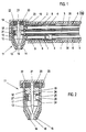
- FIGS. 1 and 2 is one of a electrically insulating material, e.g. Ceramics made provided essentially hollow cylindrical holder 1, in one end area also made of an insulating material manufactured insert 2 is pressed.
- a electrically insulating material e.g. Ceramics made provided essentially hollow cylindrical holder 1, in one end area also made of an insulating material manufactured insert 2 is pressed.
- This insert 2 is from a central, a gas supply line 3 forming tube that penetrates the front of the projecting insert 2 ends over the end face of the holder 1.
- the insert 2 also has two in a diametrical plane lying holes 4 in which serve as abutments Press-fit parts 7 are held, which in turn are held by the souls 5 of leads 6 are interspersed with play.
- connecting lines 6 are connected to one in FIG. 3 shown power supply connected in a predetermined Frequency delivers voltage pulses.
- compression springs 8 are supported Contact pins 9, which are soldered to the souls 5, to the outside push.
- the contact pins 9 are at their free end provided with an end face approach 10 with a Contact surface of a plasma generator 11 cooperates, which in a fastening device arranged on the end face of the holder 1 12 is held as one from an electrical Insulated material manufactured bracket in which the plasma generator 11 is inserted from above.
- This plasma generator 11 has a connecting part 13 an electrically insulating material, e.g. Ceramics on the tapered in its lower region and an opening 14 on its lower end face having.
- an electrically insulating material e.g. Ceramics on the tapered in its lower region and an opening 14 on its lower end face having.
- This opening 14 is from an annular anode 15 enforced in the usual way from an electrically conductive and thermally highly resilient material is manufactured and has a nozzle opening 16 in its mouth region.
- the anode 15 has a conically widening upwards Area that abuts the inside of the connecting part 13 and which merges into a cylindrical area.
- An intermediate part 17 is located on the upper end face of the anode 15 at the ring-shaped and made of an electric insulating material, e.g. Ceramics.
- an electrically good conductive material e.g. Copper
- an electrically good conductive material e.g. Copper
- an electrically conductive and thermally highly resilient Material such as Tungsten cerium oxide alloy manufactured is and in the nozzle opening 16 of the anode 15 near End region is conical.
- the anode 15, as well as the holding part 18 are for fixing the mutual position of the cathode 10 and the nozzle opening 16 of the Anode suitably fitted into the connecting part 13.
- the anode 15, the intermediate part 17 and the holding part 18 with the pressed cathode 19 form together with the connecting part 13 a module of the device that easily in the holder installed and removed from it.
- This pressure part 20 acts together with a cover 22 on the a near in the upper end of the connecting part 13 Area arranged external thread 23 is screwed on.
- the connecting part 13 is with three along a generatrix arranged radial bores 24, 25 provided, of which the Bores 24 the passage of the lugs 10 of the contact pins 9th enable and in the region of the holding part 18 or Anode 15 lie.
- the bore 25 is in the range of Intermediate part 17 arranged and aligned with a radially extending Inlet 26 of the intermediate part to one through the Inner wall of the intermediate part 17 limited chamber 27 leads to is penetrated by the cathode 19.
- the bore 25 is aligned when inserted in the holder 1 Plasma generator, which is constructed as a module, also with the in Holder 1 provided gas supply line 3.
- the connecting lines 6, the insulating jackets 28 with play in the holes 4 of the insert 2 of the holder 1 are guided, withdraw and the plasma generator 11 from above into the Insert bracket 12.
- the connecting lines 6 be released and the contact pins 9 snap into the holes 24 of the connecting part 13 and secure the position of the Plasma generator 11 in the holder 1.
- their end faces by means of the springs 8 on the holding part 8, or pressed the anode 15 and so a good electrical contact manufactured.
- a gas for example helium, CO 2 etc.
- a gas for example helium, CO 2 etc.
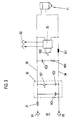
- FIG. 3 A power supply for a plasma generator according to the Fig. 1 and 2 is shown in FIG. 3.
- a capacitor bank 30 has a charging resistor 31 with the connections X1 of a controllable DC voltage source 32 connected.
- the capacitor bank 30 has one permanently connected capacitor 1C1 and one over one Switch 1S1 to this parallel connectable capacitor 1C2 on, both of which are also groups of capacitors can act.
- This capacitor bank 30 is via connecting lines 33 34th with the plasma generator 11, or not in FIG. 3 shown cathode and anode connected.
- An R / C element is connected in parallel with the capacitor bank 30, that through a capacitor 1C3 and a resistor 1R1 is formed.
- This R / C link forms in connection with the choke 1L1 connected in the connecting line 34 an RF blocking circuit which is used to protect the capacitor bank 30 is provided before RF signals.
- an igniter 35 is connected on the input side to an AC voltage source X2 and provided with a trigger switch 1S2, by its actuation an ignition pulse can be triggered.
- the capacitor battery 30 is charged during operation according to the set voltage of the DC voltage source 32, e.g. adjustable between 50V and 300V is, and that by the line resistance and the charging resistance with a certain time constant.
- the capacitor bank 30 discharges accordingly by their capacity and line resistance and the time constant given by the resistance of the arc.
- the voltage of the capacitor bank drops 30 below the arc arc voltage, so goes out this and the capacitor bank 30 recharges, whereby the process described is repeated and one Frequency results, which is determined by charging and discharging time constants is.
- the operation of the ignitor is not required.
Landscapes
- Physics & Mathematics (AREA)
- Engineering & Computer Science (AREA)
- Plasma & Fusion (AREA)
- Spectroscopy & Molecular Physics (AREA)
- Plasma Technology (AREA)
- Physical Or Chemical Processes And Apparatus (AREA)
- Ignition Installations For Internal Combustion Engines (AREA)
Applications Claiming Priority (2)
| Application Number | Priority Date | Filing Date | Title |
|---|---|---|---|
| AT28598U | 1998-05-04 | ||
| AT0028598U AT3549U1 (de) | 1998-05-04 | 1998-05-04 | Verfahren und einrichtung zum erzeugen von plasma |
Publications (3)
| Publication Number | Publication Date |
|---|---|
| EP0963140A2 true EP0963140A2 (fr) | 1999-12-08 |
| EP0963140A3 EP0963140A3 (fr) | 2002-05-15 |
| EP0963140B1 EP0963140B1 (fr) | 2004-09-08 |
Family
ID=3486492
Family Applications (1)
| Application Number | Title | Priority Date | Filing Date |
|---|---|---|---|
| EP99890141A Expired - Lifetime EP0963140B1 (fr) | 1998-05-04 | 1999-04-30 | Procédé et dispositif pour la génération de plasma |
Country Status (7)
| Country | Link |
|---|---|
| US (1) | US6225743B1 (fr) |
| EP (1) | EP0963140B1 (fr) |
| AT (1) | AT3549U1 (fr) |
| CA (1) | CA2270072C (fr) |
| CZ (1) | CZ295951B6 (fr) |
| DE (1) | DE59910426D1 (fr) |
| HU (1) | HUP9900992A3 (fr) |
Families Citing this family (3)
| Publication number | Priority date | Publication date | Assignee | Title |
|---|---|---|---|---|
| FR2807912B1 (fr) * | 2000-04-17 | 2003-06-27 | Lasers Et Tech Avancees Bureau | Procede et torche a plasma pour traiter une surface dans une cavite, et installation de remplissage bouchage s'y rapportant |
| DE102010003351A1 (de) | 2009-03-26 | 2010-12-30 | Inocon Technologie Gmbh | Kolbenmotor mit Plasmainjektionsantrieb |
| DE102009015510B4 (de) * | 2009-04-02 | 2012-09-27 | Reinhausen Plasma Gmbh | Verfahren und Strahlgenerator zur Erzeugung eines gebündelten Plasmastrahls |
Family Cites Families (13)
| Publication number | Priority date | Publication date | Assignee | Title |
|---|---|---|---|---|
| US3447322A (en) * | 1966-10-25 | 1969-06-03 | Trw Inc | Pulsed ablating thruster apparatus |
| DE1928757C3 (de) * | 1969-06-06 | 1978-11-23 | Messer Griesheim Gmbh, 6000 Frankfurt | Schaltungsanordnung zum Stabilisieren und Zünden von Schweißlichtbögen |
| US4974487A (en) * | 1984-10-05 | 1990-12-04 | Gt-Devices | Plasma propulsion apparatus and method |
| FR2611132B1 (fr) * | 1987-02-19 | 1994-06-17 | Descartes Universite Rene | Bistouri a plasma |
| DE4008405C1 (fr) * | 1990-03-16 | 1991-07-11 | Schott Glaswerke, 6500 Mainz, De | |
| JPH06502468A (ja) * | 1990-11-03 | 1994-03-17 | ドーソン ロイヤルティーズ リミテッド | 電気回路 |
| US5170030A (en) * | 1991-04-08 | 1992-12-08 | Thermal Dynamics Corporation | Plasma torch electronic pulsing circuit |
| WO1992019166A1 (fr) * | 1991-04-15 | 1992-11-12 | Nauchno-Issledovatelsky Institut Energeticheskogo Mashinostroenia Moskovskogo Gosudarstvennogo Tekhnicheskogo Universiteta Imeni N.E.Baumana | Dispositif de traitement chirurgical au plasma de tissus biologiques |
| US5296665A (en) * | 1992-05-19 | 1994-03-22 | Hypertherm, Inc. | Method of restarting a plasma arc torch using a periodic high frequency-high voltage signal |
| JPH06197930A (ja) * | 1993-01-06 | 1994-07-19 | Nippon Steel Weld Prod & Eng Co Ltd | 使用済み注射針の処理方法およびその装置 |
| US5901551A (en) * | 1994-10-24 | 1999-05-11 | Primex Technologies, Inc. | Converging constrictor for an electrothermal arcjet thruster |
| US5924278A (en) * | 1997-04-03 | 1999-07-20 | The Board Of Trustees Of The University Of Illinois | Pulsed plasma thruster having an electrically insulating nozzle and utilizing propellant bars |
| DE19806519A1 (de) * | 1998-02-17 | 1999-08-19 | Ruediger Haaga Gmbh | Vorrichtung zum Sterilisieren von Behältern mittels eines Niederdruckplasmas |
-
1998
- 1998-05-04 AT AT0028598U patent/AT3549U1/de not_active IP Right Cessation
-
1999
- 1999-04-08 HU HU9900992A patent/HUP9900992A3/hu unknown
- 1999-04-22 US US09/296,718 patent/US6225743B1/en not_active Expired - Lifetime
- 1999-04-27 CA CA002270072A patent/CA2270072C/fr not_active Expired - Fee Related
- 1999-04-30 EP EP99890141A patent/EP0963140B1/fr not_active Expired - Lifetime
- 1999-04-30 DE DE59910426T patent/DE59910426D1/de not_active Expired - Lifetime
- 1999-05-04 CZ CZ19991597A patent/CZ295951B6/cs not_active IP Right Cessation
Also Published As
| Publication number | Publication date |
|---|---|
| HUP9900992A2 (hu) | 2000-11-28 |
| DE59910426D1 (de) | 2004-10-14 |
| US6225743B1 (en) | 2001-05-01 |
| CA2270072A1 (fr) | 1999-11-04 |
| EP0963140B1 (fr) | 2004-09-08 |
| CZ159799A3 (cs) | 2000-05-17 |
| AT3549U1 (de) | 2000-04-25 |
| HUP9900992A3 (en) | 2002-12-28 |
| CZ295951B6 (cs) | 2005-12-14 |
| HU9900992D0 (en) | 1999-06-28 |
| EP0963140A3 (fr) | 2002-05-15 |
| CA2270072C (fr) | 2007-11-13 |
Similar Documents
| Publication | Publication Date | Title |
|---|---|---|
| EP0955120B1 (fr) | Méthode et appareillage pour la fusion partielle d'objets | |
| DE1298175B (de) | Schaltfunkenstrecke von geringer Eigeninduktivitaet | |
| DE102010005617A1 (de) | Verfahren zum Plasmaschneiden eines Werkstücks mittels einer Plasmaschneidanlage | |
| DE3322341C2 (fr) | ||
| DE1564333C3 (de) | Vorrichtung zur Erzeugung eines Gasentladungsplasmas | |
| DE202007018317U1 (de) | Vorrichtung zur Erzeugung eines Plasmastrahls | |
| EP0963140B1 (fr) | Procédé et dispositif pour la génération de plasma | |
| DE1440423B1 (de) | Vorrichtung und verfahren zum kontinuierlichen reinigen der oberflaeche eines in langgestreckter form vorliegenden elektrisch leitenden werkstuecks | |
| DE1539998A1 (de) | Elektronenstrahlerzeuger | |
| WO2020043794A1 (fr) | Procédé et dispositif d'usinage laser de matériau d'une pièce au moyen d'impulsion photonique | |
| DE19927557C2 (de) | Verfahren zum Vorbehandeln von zu schweißenden oder zu lötenden Werkstücken | |
| DE2434830B2 (de) | Elektronenstrahlanlage zur thermischen Bearbeitung von Metallwerkstttcken | |
| EP2018926A1 (fr) | Procédé de découpage thermique avec changement de la composition du gaz durant le découpage | |
| DE2609178A1 (de) | Plasmabrenner | |
| AT4668U1 (de) | Verfahren und einrichtung zum schweissen | |
| DE2162024C3 (de) | Vorrichtung zur Plasmaerzeugung | |
| EP0955067B1 (fr) | Procédé et appareil pour stériliser des objets | |
| DE2532261C3 (de) | Stumpfschweißverfahren | |
| EP1166942B1 (fr) | Torche plasma | |
| DE1440423C (de) | Vorrichtung und Verfahren zum konti nuierhchen Reinigen der Oberflache eines in langgestreckter Form vorhegenden, elek trisch leitenden Werkstucks | |
| DE102013106315B4 (de) | Verfahren und Vorrichtung zum Erzeugen eines physikalischen Plasmas | |
| AT407401B (de) | Verfahren zum härten von oberflächen | |
| EP1043108A2 (fr) | Appareil de soudage du plasma | |
| DE1936272C (de) | Hochfrequenzplasmabrenner | |
| DE1440541B2 (de) | Elektrisches plasmageraet zum erhitzen, schneiden und schweissen eines werkstuecks |
Legal Events
| Date | Code | Title | Description |
|---|---|---|---|
| PUAI | Public reference made under article 153(3) epc to a published international application that has entered the european phase |
Free format text: ORIGINAL CODE: 0009012 |
|
| AK | Designated contracting states |
Kind code of ref document: A2 Designated state(s): AT BE CH CY DE DK ES FI FR GB GR IE IT LI LU MC NL PT SE |
|
| AX | Request for extension of the european patent |
Free format text: AL;LT;LV;MK;RO;SI |
|
| PUAL | Search report despatched |
Free format text: ORIGINAL CODE: 0009013 |
|
| AK | Designated contracting states |
Kind code of ref document: A3 Designated state(s): AT BE CH CY DE DK ES FI FR GB GR IE IT LI LU MC NL PT SE |
|
| AX | Request for extension of the european patent |
Free format text: AL;LT;LV;MK;RO;SI |
|
| 17P | Request for examination filed |
Effective date: 20020701 |
|
| AKX | Designation fees paid |
Designated state(s): CH DE ES FR GB IT LI NL SE |
|
| 17Q | First examination report despatched |
Effective date: 20030211 |
|
| GRAP | Despatch of communication of intention to grant a patent |
Free format text: ORIGINAL CODE: EPIDOSNIGR1 |
|
| GRAS | Grant fee paid |
Free format text: ORIGINAL CODE: EPIDOSNIGR3 |
|
| GRAA | (expected) grant |
Free format text: ORIGINAL CODE: 0009210 |
|
| AK | Designated contracting states |
Kind code of ref document: B1 Designated state(s): CH DE ES FR GB IT LI NL SE |
|
| PG25 | Lapsed in a contracting state [announced via postgrant information from national office to epo] |
Ref country code: NL Free format text: LAPSE BECAUSE OF FAILURE TO SUBMIT A TRANSLATION OF THE DESCRIPTION OR TO PAY THE FEE WITHIN THE PRESCRIBED TIME-LIMIT Effective date: 20040908 Ref country code: GB Free format text: LAPSE BECAUSE OF FAILURE TO SUBMIT A TRANSLATION OF THE DESCRIPTION OR TO PAY THE FEE WITHIN THE PRESCRIBED TIME-LIMIT Effective date: 20040908 |
|
| REG | Reference to a national code |
Ref country code: GB Ref legal event code: FG4D Free format text: NOT ENGLISH |
|
| REG | Reference to a national code |
Ref country code: CH Ref legal event code: EP |
|
| REG | Reference to a national code |
Ref country code: IE Ref legal event code: FG4D Free format text: GERMAN |
|
| REF | Corresponds to: |
Ref document number: 59910426 Country of ref document: DE Date of ref document: 20041014 Kind code of ref document: P |
|
| PG25 | Lapsed in a contracting state [announced via postgrant information from national office to epo] |
Ref country code: SE Free format text: LAPSE BECAUSE OF FAILURE TO SUBMIT A TRANSLATION OF THE DESCRIPTION OR TO PAY THE FEE WITHIN THE PRESCRIBED TIME-LIMIT Effective date: 20041208 |
|
| PG25 | Lapsed in a contracting state [announced via postgrant information from national office to epo] |
Ref country code: ES Free format text: LAPSE BECAUSE OF FAILURE TO SUBMIT A TRANSLATION OF THE DESCRIPTION OR TO PAY THE FEE WITHIN THE PRESCRIBED TIME-LIMIT Effective date: 20041219 |
|
| NLV1 | Nl: lapsed or annulled due to failure to fulfill the requirements of art. 29p and 29m of the patents act | ||
| GBV | Gb: ep patent (uk) treated as always having been void in accordance with gb section 77(7)/1977 [no translation filed] |
Effective date: 20040908 |
|
| REG | Reference to a national code |
Ref country code: IE Ref legal event code: FD4D |
|
| PG25 | Lapsed in a contracting state [announced via postgrant information from national office to epo] |
Ref country code: LI Free format text: LAPSE BECAUSE OF NON-PAYMENT OF DUE FEES Effective date: 20050430 Ref country code: CH Free format text: LAPSE BECAUSE OF NON-PAYMENT OF DUE FEES Effective date: 20050430 |
|
| ET | Fr: translation filed | ||
| PLBE | No opposition filed within time limit |
Free format text: ORIGINAL CODE: 0009261 |
|
| STAA | Information on the status of an ep patent application or granted ep patent |
Free format text: STATUS: NO OPPOSITION FILED WITHIN TIME LIMIT |
|
| 26N | No opposition filed |
Effective date: 20050609 |
|
| REG | Reference to a national code |
Ref country code: CH Ref legal event code: PL |
|
| PGFP | Annual fee paid to national office [announced via postgrant information from national office to epo] |
Ref country code: IT Payment date: 20070510 Year of fee payment: 9 |
|
| PG25 | Lapsed in a contracting state [announced via postgrant information from national office to epo] |
Ref country code: IT Free format text: LAPSE BECAUSE OF NON-PAYMENT OF DUE FEES Effective date: 20080430 |
|
| PGFP | Annual fee paid to national office [announced via postgrant information from national office to epo] |
Ref country code: FR Payment date: 20090416 Year of fee payment: 11 |
|
| REG | Reference to a national code |
Ref country code: FR Ref legal event code: ST Effective date: 20101230 |
|
| PG25 | Lapsed in a contracting state [announced via postgrant information from national office to epo] |
Ref country code: FR Free format text: LAPSE BECAUSE OF NON-PAYMENT OF DUE FEES Effective date: 20100430 |
|
| PGFP | Annual fee paid to national office [announced via postgrant information from national office to epo] |
Ref country code: DE Payment date: 20150428 Year of fee payment: 17 |
|
| REG | Reference to a national code |
Ref country code: DE Ref legal event code: R119 Ref document number: 59910426 Country of ref document: DE |
|
| PG25 | Lapsed in a contracting state [announced via postgrant information from national office to epo] |
Ref country code: DE Free format text: LAPSE BECAUSE OF NON-PAYMENT OF DUE FEES Effective date: 20161101 |