EP0963280B1 - Haarschneidemaschine mit schnittlängen-verstelleinrichtung - Google Patents
Haarschneidemaschine mit schnittlängen-verstelleinrichtung Download PDFInfo
- Publication number
- EP0963280B1 EP0963280B1 EP98916812A EP98916812A EP0963280B1 EP 0963280 B1 EP0963280 B1 EP 0963280B1 EP 98916812 A EP98916812 A EP 98916812A EP 98916812 A EP98916812 A EP 98916812A EP 0963280 B1 EP0963280 B1 EP 0963280B1
- Authority
- EP
- European Patent Office
- Prior art keywords
- slide
- comb
- clipping
- machine according
- cutting machine
- Prior art date
- Legal status (The legal status is an assumption and is not a legal conclusion. Google has not performed a legal analysis and makes no representation as to the accuracy of the status listed.)
- Expired - Lifetime
Links
- 230000008878 coupling Effects 0.000 claims abstract description 5
- 238000010168 coupling process Methods 0.000 claims abstract description 5
- 238000005859 coupling reaction Methods 0.000 claims abstract description 5
- 238000005520 cutting process Methods 0.000 claims description 77
- 238000006073 displacement reaction Methods 0.000 claims description 11
- 239000012815 thermoplastic material Substances 0.000 claims description 3
- 230000010355 oscillation Effects 0.000 claims 1
- 239000000725 suspension Substances 0.000 claims 1
- 238000010276 construction Methods 0.000 abstract description 5
- 230000003534 oscillatory effect Effects 0.000 abstract description 2
- 208000019300 CLIPPERS Diseases 0.000 description 15
- 208000021930 chronic lymphocytic inflammation with pontine perivascular enhancement responsive to steroids Diseases 0.000 description 15
- 238000003860 storage Methods 0.000 description 4
- 230000005540 biological transmission Effects 0.000 description 2
- 238000004519 manufacturing process Methods 0.000 description 2
- 230000009286 beneficial effect Effects 0.000 description 1
- 230000000694 effects Effects 0.000 description 1
- 238000005516 engineering process Methods 0.000 description 1
- 210000003746 feather Anatomy 0.000 description 1
- 238000005304 joining Methods 0.000 description 1
- 229920001169 thermoplastic Polymers 0.000 description 1
- 239000004416 thermosoftening plastic Substances 0.000 description 1
- 210000003813 thumb Anatomy 0.000 description 1
Images



Classifications
-
- B—PERFORMING OPERATIONS; TRANSPORTING
- B26—HAND CUTTING TOOLS; CUTTING; SEVERING
- B26B—HAND-HELD CUTTING TOOLS NOT OTHERWISE PROVIDED FOR
- B26B19/00—Clippers or shavers operating with a plurality of cutting edges, e.g. hair clippers, dry shavers
- B26B19/20—Clippers or shavers operating with a plurality of cutting edges, e.g. hair clippers, dry shavers with provision for shearing hair of preselected or variable length
- B26B19/205—Clippers or shavers operating with a plurality of cutting edges, e.g. hair clippers, dry shavers with provision for shearing hair of preselected or variable length by adjustment of the cutting members
Definitions
- the invention relates to a hair clipper with a Cutting length adjustment device according to the preamble of the claim 1.
- Hair clippers with a cutting length adjustment device are known for example from DE 33 10 706 C2.
- This hair clipper has a cutting set that consists of a fixed shear comb and one essentially parallel to the front edge, i.e. in the transverse direction, oscillating drivable clipper.
- the shear knife has one for this fork-shaped driver in which an eccentric pin of Drive motor engages.
- the cutting length is now changed in that with a bevel Contour course of the shear comb on its underside the position of the shear knife in relation to the front edge of the Shear comb is changeable in the longitudinal direction.
- This is a Actuator in the form of a slide mounted in the housing provided that the pivotable via a toothing on the Acts on the cutter. A shift of the actuator causes a shift of the shear knife in Longitudinal direction.
- the invention was therefore based on the problem of a hair clipper to improve the type mentioned at the beginning, that it no longer has the disadvantages described.
- the cutting length adjustment device should be improved be the constructive structure and thus the to simplify manufacturing-related effort.
- the invention is based on the idea of the entire cutting length adjustment device fully integrated into the cutting set and at the same time to store the shaving knife freely swinging.
- the actuating element is also part of the cutting set. So it succeeds a cutting set including the cutting length adjustment device as an independent assembly, independent of the housing to realize. There are no actuators on the housing to provide more for adjusting the cutting length, so that this considerably simplifies the construction.
- hair clippers interchangeable cutting sets possible, optionally with and without providing cutting length adjustment device, without the Change the design of the hair clipper.
- two bearing blocks are provided on the slide take up at least one spring element.
- the shear knife is with connected to the at least one spring element such that it held under pretension against the shear comb and is stored in the manner of a parallelogram guide.
- a carrier is preferably provided which receives the carriage.
- the carrier is attached to the shaving comb for this purpose, and preferably in the area of a molded on the shear comb or attached comb plate.
- the sledge is thus on Carrier and thus held on the shaving comb or the comb plate and led.
- the actuating element is according to a preferred embodiment rotatably mounted on the carrier and / or on the comb plate.
- This type of storage has the advantage that it does not requires additional components. Rather, by at known measures a storage by means of pins and corresponding Holes can be reached.
- This type of storage enables by a simple rotating or swiveling movement of the actuator, the displacement movement of the To manipulate sledges specifically. A rotating or swiveling movement enables a very exact setting of the desired Position, for example, via locking means known per se is fixable.
- a particularly simple implementation of the rotating or swiveling movement the actuator into the desired translation or Sliding movement of the slide is particularly easy with the help of a driver pin that fits into a corresponding Link groove engages and interacts with this.
- the driver pin can, for example, on the actuating element be attached and with the slotted groove on the slide work together. In the sense of a reversal of function, it is just as possible, the driver pin on the slide and the Install the link groove on the actuating element.
- a gearwheel on the actuating element can also be used be appropriate with at least one corresponding Rack segment interacts on the slide.
- the cutting set according to the invention including the cutting length adjustment device can alternatively be formed in this way be that either the shear comb and / or the carrier on the housing can be set so that the shear knife to adjust the Cutting length is shifted.
- the sledge can also be used be fixed on the housing so that the setting of the Cutting length is done by adjusting the shaving comb.
- a displacement of the shear comb can also be realized in this way be that an additional holder is provided with is connected to the carrier and in which the shear comb in Is slidably mounted in the longitudinal direction.
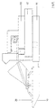
- a hair clipper with Cutting length adjustment device results from Fig. 1.
- a drive motor 4 is used, the an eccentric 6 a shear knife 20 in the transverse direction, d. H. in a plane perpendicular to the section plane shown, oscillating drives.
- the shear knife 20 is against a shear comb 10 directed so that a cutting set 8 is formed.
- the Cutting set 8 can be replaced in a manner known per se designed, d. H. it is detachably connected to the housing 2.
- the special feature is that the cutting set 8 a integrated cutting length adjustment device that a shift to set the desired cutting length of the shear knife 20 in the longitudinal direction.
- she consists essentially of an actuator 40 which on a Sled 30 acts.
- the carriage 30 is with the shear knife 20 connected so that the actuator 40th generated displacement movement of the carriage 30 immediately the shear knife 20 is transmitted.
- Fig. 1 From Fig. 1 it is therefore immediately apparent that for Longitudinal adjustment of the shear knife 20 relative to the shear comb 10 no housing-side components are required.
- the desired cutting length is therefore only set through components integrated into the cutting set 8 are.
- the cutting set 8 is therefore also particularly suitable beneficial in exchange for existing ones Cutting sets without such an adjustment option used to become. A simple retrofit to existing hair clippers is given.
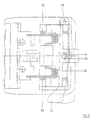
- the cutting set 8 is compared to FIG. 1 enlarged and with a differently designed actuator 40 shown.
- a comb plate 12 is in one piece on the shear comb 10 molded onto the entire cutting length adjustment device records.
- the shear knife 20 is placed in the front area, which via a driver 21 from (not shown here) Eccentric 6 can be driven.
- the actuating element 40 is designed as a swivel lever and guided between the comb plate 12 and a carrier 50.
- the Actuator 40 has a pin 41 which in a corresponding slot groove 32 engages on the carriage 30.
- the carriage 30 is taken and in Shifted towards the front edge of the shear comb 10, until the position shown in Fig. 2c is reached.
- the maximum possible displacement V is due to the length of the link groove 32 in connection with the arrangement of the pin 41 in predetermined with respect to the actuator 40.
- the carriage 30 has guide pins 36 which are in guide grooves 56 of the carrier 50 engage. This ensures that the carriage 30 is an exactly extending in the longitudinal direction Moving movement executes, even if - as in the present Case - the force applied to the adjustment off-center he follows.
- a peculiarity of the carriage 30 is that in symmetrical arrangement of two bearing blocks 31 for a spring element 60 are molded.
- the spring element 60 is in one piece executed and has two spaced and parallel to each other extending spring arms 62 and two spring coils 64, with which the spring element 60 is inserted into the bearing blocks 31.
- the spring arms 62 engage the shear knife 20 and thus establish the connection to the carriage 30.
- the spring coils 64 generate a biasing force with which the shear knife 20 is kept pressed against the shear comb 10.
- the arrangement of the spring arms 62 also provides a parallelogram guide represents the oscillatory displacement movement enables transverse to the longitudinal axis.
- FIGS. 3a and 3b The variant shown in FIGS. 3a and 3b has as Actuator 40 an adjusting wheel, the two together meshing gears 43 drives.
- the gears 43 are each in engagement with rack segments 33, which on the slide 30th are attached.
- a rotary movement of the adjusting wheel is thus implemented in a sliding movement of the carriage 30.
- This Type of coupling between actuator 40 and carriage 30 has the advantage that the force is applied to the slide 30 completely symmetrical to the longitudinal axis, and thus to the direction of displacement, he follows.
- the operating forces can can be kept low since there is no tilting of the slide 30 in the guide groove 56 occurs more.
- FIGS. 4a and 4b has an eccentric lever as the actuating element 40, which is off-center between the comb plate 12 and the carrier 50 around the Pivot axis 49 is rotatably mounted.
- the end has the Eccentric lever in turn a pin 41 on the slide 30 attacks in the area of a slide extension 34.
- the actuating element 40 is arranged approximately laterally to the cutting set 8. This can be done Ergonomic points of view can be advantageous as an activity the cutting length adjustment with the thumb too is possible during the cutting process.
- the variant shown in Fig. 5 is characterized by a particularly simple construction.
- a pivot lever is provided, the one single gear 43 carries.
- the gear 43 is on a rack segment 33 of the carriage 30 aligned. A shift of the carriage 30 is thus by a rotational movement of the pivot lever.
- actuating element 40 in the form of an eccentric lever, which also is rotatably mounted off-center about the pivot axis 49. Also is a pin 41 attached to the eccentric lever, which in a Link groove 32 engages on slide 30.
- the pivot axis 49 is as far as possible from the axis of symmetry positioned away. So it succeeds in the force application point on the carriage 30 with respect to the axis of symmetry to keep largely constant.
- the shift of the point of attack of the pin 41 on the carriage 30 is in transit the displacement distance between the two end points comparatively small and is due to the leadership in the guide grooves 56 compensated.
- the carriage 30 on (housing 2 not shown here) can be fixed.
- the carriage 30 has holding webs, not shown, which snap into corresponding grooves on housing 2.
- the actuating element 40 thus becomes the comb plate 12 moved with the shear comb 10 in the longitudinal direction.
- the adjustment is the cutting length by shifting the shear comb 10 realized, in which case one with the carrier 50 connected holder 70 is present in which the shear comb 10 is guided longitudinally.
- the actuator 40 acts directly on the shear comb 10 and shifts this in relation to the shear knife 20.
- This variant has manufacturing-related advantages since the carrier 50 can be fused to the holder 70, provided both components are made of a thermoplastic. Usual connecting elements, such as screws or Rivets can be omitted completely.
Landscapes
- Life Sciences & Earth Sciences (AREA)
- Forests & Forestry (AREA)
- Engineering & Computer Science (AREA)
- Mechanical Engineering (AREA)
- Dry Shavers And Clippers (AREA)
- Knives (AREA)
Description
- Fig. 1
- Haarschneidemaschine im Längsschnitt, grundsätzlicher Aufbau,
- Fig. 2a
- Schneidsatz, Zapfenführung in Kulissennut, Längsschnitt,
- Fig. 2b
- Schneidsatz gemäß Fig. 2a, Draufsicht,
- Fig. 2c
- Schneidsatz gemäß Fig. 2b, abweichende Position des Schermessers,
- Fig. 3a
- Schneidsatz, Verstellrad mit symmetrischer Krafteinleitung, Längsschnitt,
- Fig. 3b
- Schneidsatz gemäß Fig. 3a, Draufsicht,
- Fig. 4a
- Schneidsatz, mit Exzenterhebel und Verstellschieber, Längsschnitt,
- Fig. 4b
- Schneidsatz gemäß Fig. 4a, Draufsicht,
- Fig. 5
- Schneidsatz mit Schwenkhebel, Zahnrad einseitig wirkend, Draufsicht,
- Fig. 6
- Schneidsatz mit Exzenterhebel, Zapfen zentral angreifend, Draufsicht,
- Fig. 7
- Schneidsatz, Schlitten am Gehäuse festgelegt, Längsschnitt und
- Fig. 8
- Schneidsatz, Scherkamm mit Auszug, Längs- schnitt.
- 2
- Gehäuse
- 4
- Motor
- 6
- Exzenter
- 8
- Schneidsatz
- 10
- Scherkamm
- 12
- Kammplatte
- 20
- Schermesser
- 21
- Mitnehmer
- 30
- Schlitten
- 31
- Lagerbock
- 32
- Kulissennut
- 33
- Zahnstangensegment
- 34
- Schieberansatz
- 36
- Führungszapfen
- 40
- Betätigungselement
- 41
- Zapfen
- 43
- Zahnrad
- 49
- Schwenkachse
- 50
- Träger
- 56
- Führungsnut
- 60
- Federelement
- 62
- Federarm
- 64
- Federwendel
- 70
- Halter
- V
- Verschiebeweg
Claims (12)
- Haarschneidemaschine mit einer auf einen Schneidsatz (8) einwirkenden Schnittlängen-Verstelleinrichtung,dadurch gekennzeichnet, daßa) der Schneidsatz (8) bestehend zumindest aus einem feststehenden Scherkamm (10) und einem im wesentlichen parallel zur Vorderkante des Scherkammes (10) in Querrichtung oszillierend antreibbaren Schermesser (20),b) die Schnittlängen-Verstelleinrichtung bestehend zumindest aus einem Betätigungselement (40) und einem Schlitten (30), wobei
der Schlitten (30)das Betätigungselement (40)gegenüber dem Scherkamm (10) in Längsrichtung verschiebbar gelagert,mit dem Schermesser (20) verbunden undvon dem Betätigungselement (40) im Bereich zwischen einer vorderen und einer hinteren Endstellung positionierbar ist, undüber Koppelelemente (32,41) mit dem Schlitten (30) verbunden ist unddessen Verschiebung senkrecht zur Vorderkante des Schermessers (20) in Längsrichtung ermöglicht,die Schnittlängenverstelleinrichtung vollständig in den Schneidsatz (8) integriert ist, undzwei am Schlitten (30) angebrachte Lagerböcke (31) vorgesehen sind, in die wenigstens ein Federelement (60) eingesetzt ist, wobei das wenigstens eine Federelement (60) mit dem Schermesser (20) derart verbunden ist, daß dieses unter Vorspannung gegen den Scherkamm (10) gedrückt gehalten und gleichzeitig nach Art einer Parallelogrammführung gelagert ist. - Haarschneidemaschine nach Anspruch 1, dadurch gekennzeichnet, daß die Lagerböcke (31) einstückig am Schlitten (30) angeformt sind.
- Haarschneidemaschine nach Anspruch 2, gekennzeichnet durch einen Träger (50), der den Schlitten (30) aufnimmt und der am Scherkamm (10), vorzugsweise im Bereich einer einstückig angeformten Kammplatte (12), befestigt ist.
- Haarschneidemaschine nach Anspruch 3, dadurch gekennzeichnet, daß das Betätigungselement (40) am Träger (50) und/oder an der Kammplatte (12) drehbar gelagert ist.
- Haarschneidemaschine nach einem der Ansprüche 3 bis 4, gekennzeichnet durch einen am Betätigungselement (40) oder am Schlitten (30) angebrachten Mitnehmerzapfen (41), der in eine korrespondierende Kulissennut (32) am Schlitten (30) oder am Betätigungselement (40) eingreift.
- Haarschneidemaschine nach einem der Ansprüche 2 bis 4, gekennzeichnet durch ein am Betätigungselement (40) angebrachtes Zahnrad (43), das mit wenigstens einem korrespondierenden Zahnstangensegment (33) am Schlitten (30) zusammenwirkt.
- Haarschneidemaschine nach Anspruch 6, gekennzeichnet durch zwei symmetrisch zur Längsachse angeordnete, gegenläufig angetriebene Zahnräder (43), die mit zwei korrespondierenden, symmetrisch zur Längsachse angeordneten Zahnstangensegmenten (33) zusammenwirken.
- Haarschneidemaschine nach einem der vorstehenden Ansprüche, dadurch gekennzeichnet, daß der Scherkamm (10) und/oder der Träger (50) am Gehäuse (2) festlegbar sind.
- Haarschneidemaschine nach einem der Ansprüche 1 bis 7, dadurch gekennzeichnet, daß der Schlitten (30) am Gehäuse (2) festlegbar ist.
- Haarschneidemaschine nach Anspruch 9, gekennzeichnet durch einen Halter (70), in dem der Scherkamm (20) in Längsrichtung verschiebbar gelagert ist und der mit dem Träger (50) verbunden ist.
- Haarschneidemaschine nach Anspruch 10, dadurch gekennzeichnet, daß der Träger (50) und der Halter (70) aus thermoplastischem Material geformt und miteinander verschmolzen sind.
- Haarschneidemaschine nach einem der Ansprüche 1 bis 8, dadurch gekennzeichnet, daß die Kammplatte (12) und der Halter (70) aus thermoplastischem Material geformt und miteinander verschmolzen sind.
Applications Claiming Priority (3)
| Application Number | Priority Date | Filing Date | Title |
|---|---|---|---|
| DE19708145 | 1997-02-28 | ||
| DE19708145A DE19708145C2 (de) | 1997-02-28 | 1997-02-28 | Haarschneidemaschine mit Schnittlängen-Verstelleinrichtung |
| PCT/DE1998/000587 WO1998038016A1 (de) | 1997-02-28 | 1998-02-27 | Haarschneidemaschine mit schnittlängen-verstelleinrichtung |
Publications (2)
| Publication Number | Publication Date |
|---|---|
| EP0963280A1 EP0963280A1 (de) | 1999-12-15 |
| EP0963280B1 true EP0963280B1 (de) | 2001-11-21 |
Family
ID=7821825
Family Applications (1)
| Application Number | Title | Priority Date | Filing Date |
|---|---|---|---|
| EP98916812A Expired - Lifetime EP0963280B1 (de) | 1997-02-28 | 1998-02-27 | Haarschneidemaschine mit schnittlängen-verstelleinrichtung |
Country Status (7)
| Country | Link |
|---|---|
| US (1) | US6260276B1 (de) |
| EP (1) | EP0963280B1 (de) |
| CN (1) | CN1087212C (de) |
| AT (1) | ATE209084T1 (de) |
| DE (2) | DE19708145C2 (de) |
| ES (1) | ES2165154T3 (de) |
| WO (1) | WO1998038016A1 (de) |
Families Citing this family (34)
| Publication number | Priority date | Publication date | Assignee | Title |
|---|---|---|---|---|
| DE19850919A1 (de) | 1998-11-05 | 2000-05-11 | Moser Elektrogeraete Gmbh | Haarschneidemaschine mit Schnittlängen-Verstelleinrichtung |
| US6742262B2 (en) * | 2001-04-09 | 2004-06-01 | Conair Corporation | Detachable and adjustable blade assembly |
| JP2005535424A (ja) * | 2002-08-16 | 2005-11-24 | ウエラ アクチェンゲゼルシャフト | バリカン |
| DE10302998B4 (de) * | 2003-01-27 | 2007-07-12 | Wahl Gmbh | Schneidsatz für Haarschneidemaschinen mit einer Doppelparallel-Federführung |
| EP1761368A2 (de) * | 2004-06-14 | 2007-03-14 | Koninklijke Philips Electronics N.V. | Schneid-/schervorrichtung |
| JP4103873B2 (ja) * | 2004-09-01 | 2008-06-18 | 松下電工株式会社 | ヘアカッターのコーム振動防止構造 |
| TWM277576U (en) * | 2005-04-15 | 2005-10-11 | Jeng Shyuan Prec Co Ltd | Hair cutter having improved assembled structure |
| US7234242B2 (en) * | 2005-11-14 | 2007-06-26 | Woody Yao | Adjustable apparatus for hair clipper |
| JP4127299B2 (ja) * | 2006-06-16 | 2008-07-30 | 松下電工株式会社 | ヘアークリッパー |
| US7703210B2 (en) * | 2007-12-11 | 2010-04-27 | Specialife Industries Limited | Blade driving assembly for an adjustable hair clipper |
| DE102008010444B4 (de) * | 2008-02-21 | 2012-03-22 | Wahl Gmbh | Schneidsatz für eine Haarschneidemaschine |
| US20080282550A1 (en) * | 2008-06-30 | 2008-11-20 | Andis Company | Blade assembly |
| DE102009015276B4 (de) | 2009-04-01 | 2015-10-15 | Wahl Gmbh | Haarschneidemaschine mit auswechselbarem Schneidsatz und Schnittlängen-Verstelleinrichtung |
| DE102009035232B4 (de) * | 2009-07-29 | 2014-10-16 | Wahl Gmbh | Schneidsatz für Haarschneidemaschinen |
| DE102011008314B4 (de) * | 2011-01-11 | 2017-07-13 | Wahl Gmbh | Haarschneidemaschine |
| US8844142B2 (en) | 2011-03-18 | 2014-09-30 | Spectrum Brands, Inc. | Adjustable comb assembly for hair cutting appliance |
| JP6157495B2 (ja) | 2011-11-28 | 2017-07-05 | コーニンクレッカ フィリップス エヌ ヴェKoninklijke Philips N.V. | 可変カッティング長さヘアクリッピングシステム |
| US10093029B2 (en) | 2012-07-31 | 2018-10-09 | Koninklijke Philips N.V. | Hair clipping device |
| BR112015001896B1 (pt) | 2012-07-31 | 2020-09-29 | Koninklijke Philips N.V. | Dispositivo de corte de pêlos, e conjunto de corte para uso em um dispositivo de corte de pêlos |
| CN102990684B (zh) * | 2012-12-06 | 2014-11-05 | 浙江百特电器有限公司 | 可方便拆卸电池盒的剃毛装置 |
| EP3415000B1 (de) * | 2014-09-16 | 2022-06-08 | Spectrum Brands, Inc. | Fellpflegewerkzeug und -verfahren |
| US11014253B2 (en) | 2014-09-17 | 2021-05-25 | Andis Company | Blade assembly having entrapped spring |
| US9770836B2 (en) * | 2014-09-17 | 2017-09-26 | Andis Company | Blade assembly having entrapped spring |
| CN107107352B (zh) | 2014-11-06 | 2019-06-14 | 皇家飞利浦有限公司 | 毛发修剪装置 |
| CN105313149A (zh) * | 2014-12-19 | 2016-02-10 | 兰州大学 | 一种手持式发电装置及手持发电式多功能剪刀 |
| US9545729B2 (en) * | 2015-03-26 | 2017-01-17 | Wahl Clipper Corporation | Hair trimmer blade set with adjustable blades |
| WO2017153482A1 (en) | 2016-03-08 | 2017-09-14 | Koninklijke Philips N.V. | Blade set manufacturing method, blade set and hair cutting appliance |
| EP3461603A1 (de) * | 2017-09-29 | 2019-04-03 | Koninklijke Philips N.V. | Haarschneidevorrichtung |
| JP6944710B2 (ja) * | 2018-02-08 | 2021-10-06 | 大東電機工業株式会社 | バリカン刃 |
| CA3113634A1 (en) * | 2018-08-17 | 2020-02-20 | Andis Company | Adjustable blade assembly having magnetic tensioning |
| CN110900667B (zh) * | 2019-10-15 | 2025-06-10 | 上海奔腾电工有限公司 | 可调节刀头和限位梳的防水电推剪 |
| US20230256632A1 (en) * | 2022-02-17 | 2023-08-17 | Walker & Co. Brands, Inc. | 2-in-1 modular grooming device |
| DE102023118452B3 (de) * | 2023-07-12 | 2024-10-31 | Wahl Gmbh | Vorrichtung zur Erfassung der Schnittlänge einer Haarschneidevorrichtung und Haarschneidevorrichtung aufweisend eine solche Vorrichtung |
| CN117817722A (zh) * | 2023-12-21 | 2024-04-05 | 柯恒 | 一种理发方法、理发设备、计算机可读存储介质及终端 |
Family Cites Families (10)
| Publication number | Priority date | Publication date | Assignee | Title |
|---|---|---|---|---|
| US1774046A (en) * | 1929-09-16 | 1930-08-26 | Wahl Clipper Corp | Clipper-blade construction |
| DE813003C (de) * | 1948-12-03 | 1951-09-06 | Charles Frederick Walker | Haarschneidemaschine |
| DE814117C (de) * | 1948-12-24 | 1951-09-20 | Wilhelm Oehler | Haarschneidemaschine |
| DE1193834B (de) * | 1962-05-10 | 1965-05-26 | Wahl Clipper Corp | Einstellbare Haarschneidemaschine |
| US4148485A (en) | 1977-09-19 | 1979-04-10 | Atari, Inc. | Driving games method for automatically controlled cars |
| JPS5454757A (en) * | 1977-10-06 | 1979-05-01 | Matsushita Electric Works Ltd | Spring device for pushing up reciprocating blade |
| JPS6037753B2 (ja) * | 1981-12-15 | 1985-08-28 | 松下電工株式会社 | ヘアカツタ− |
| DE3310706A1 (de) * | 1983-03-24 | 1984-09-27 | Wella Ag, 6100 Darmstadt | Elektrische haarschneidemaschine |
| JP3080975B2 (ja) * | 1990-06-15 | 2000-08-28 | 松下電工株式会社 | 電気バリカン |
| US5367772A (en) * | 1992-05-26 | 1994-11-29 | Matsushita Electric Works, Ltd. | Hair clipper |
-
1997
- 1997-02-28 DE DE19708145A patent/DE19708145C2/de not_active Expired - Fee Related
-
1998
- 1998-02-27 CN CN98801581A patent/CN1087212C/zh not_active Expired - Lifetime
- 1998-02-27 WO PCT/DE1998/000587 patent/WO1998038016A1/de not_active Ceased
- 1998-02-27 EP EP98916812A patent/EP0963280B1/de not_active Expired - Lifetime
- 1998-02-27 ES ES98916812T patent/ES2165154T3/es not_active Expired - Lifetime
- 1998-02-27 AT AT98916812T patent/ATE209084T1/de not_active IP Right Cessation
- 1998-02-27 US US09/355,859 patent/US6260276B1/en not_active Expired - Lifetime
- 1998-02-27 DE DE59802715T patent/DE59802715D1/de not_active Expired - Lifetime
Also Published As
| Publication number | Publication date |
|---|---|
| DE19708145C2 (de) | 2001-09-06 |
| ATE209084T1 (de) | 2001-12-15 |
| US6260276B1 (en) | 2001-07-17 |
| ES2165154T3 (es) | 2002-03-01 |
| EP0963280A1 (de) | 1999-12-15 |
| DE59802715D1 (de) | 2002-02-21 |
| WO1998038016A1 (de) | 1998-09-03 |
| CN1087212C (zh) | 2002-07-10 |
| CN1242730A (zh) | 2000-01-26 |
| DE19708145C1 (de) | 1998-08-27 |
Similar Documents
| Publication | Publication Date | Title |
|---|---|---|
| DE19708145C2 (de) | Haarschneidemaschine mit Schnittlängen-Verstelleinrichtung | |
| EP1140436B1 (de) | Haarschneidemaschine | |
| DE3222120C2 (de) | ||
| EP1641601B1 (de) | Elektrisches haarschneidegerät | |
| DE19543095C1 (de) | Trockenrasierapparat | |
| EP0716897B1 (de) | Pendelhubantrieb für Stichsägen | |
| DE3814554A1 (de) | Schneidmesser | |
| EP0600998B1 (de) | Epilationsgerät | |
| EP1161325A1 (de) | Elektrischer rasierapparat | |
| DE102007015805B4 (de) | Schneidsatz für elektrische Haarschneidemaschinen | |
| AT398721B (de) | Rasierapparat mit einer verstellbaren zahnschneideinrichtung | |
| DE69106674T2 (de) | Elektrisches Rasiergerät mit einer flexiblen Schneiderhalterung. | |
| DE10325391A1 (de) | Chirurgisches Sägeblatt | |
| DE69936127T2 (de) | Sägeblattaufspannvorrichtung | |
| EP0008483B1 (de) | Langhaarscherteil, insbesondere für Trockenrasierapparate | |
| DE2028063C3 (de) | Antriebs- und Kupplungsanordnung für ein Trockenrasiergerät | |
| DE10302998A1 (de) | Schneidsatz für Haarschneidemaschinen | |
| EP1126955B1 (de) | Haarschneidemaschine mit schnittlängen-verstelleinrichtung | |
| DE2939057B2 (de) | Schneidevorrichtung zum Einbringen von Schnitten in die Haut | |
| DE102004045624A1 (de) | Hubsägemaschine | |
| DE3310706C2 (de) | ||
| DE102007007377B4 (de) | Maschinenreibahle | |
| DE29724477U1 (de) | Haarschneidemaschine mit Schnittlängen-Verstelleinrichtung | |
| DE3509184A1 (de) | Elektro-rasierapparat | |
| DE20006838U1 (de) | Schneidsatz für eine Haarschneidemaschine |
Legal Events
| Date | Code | Title | Description |
|---|---|---|---|
| PUAI | Public reference made under article 153(3) epc to a published international application that has entered the european phase |
Free format text: ORIGINAL CODE: 0009012 |
|
| 17P | Request for examination filed |
Effective date: 19990506 |
|
| AK | Designated contracting states |
Kind code of ref document: A1 Designated state(s): AT BE CH DE DK ES FI FR GB GR IE IT LI LU MC NL PT SE |
|
| GRAG | Despatch of communication of intention to grant |
Free format text: ORIGINAL CODE: EPIDOS AGRA |
|
| GRAG | Despatch of communication of intention to grant |
Free format text: ORIGINAL CODE: EPIDOS AGRA |
|
| GRAH | Despatch of communication of intention to grant a patent |
Free format text: ORIGINAL CODE: EPIDOS IGRA |
|
| 17Q | First examination report despatched |
Effective date: 20010427 |
|
| GRAH | Despatch of communication of intention to grant a patent |
Free format text: ORIGINAL CODE: EPIDOS IGRA |
|
| GRAA | (expected) grant |
Free format text: ORIGINAL CODE: 0009210 |
|
| AK | Designated contracting states |
Kind code of ref document: B1 Designated state(s): AT BE CH DE DK ES FI FR GB GR IE IT LI LU MC NL PT SE |
|
| PG25 | Lapsed in a contracting state [announced via postgrant information from national office to epo] |
Ref country code: IE Free format text: LAPSE BECAUSE OF FAILURE TO SUBMIT A TRANSLATION OF THE DESCRIPTION OR TO PAY THE FEE WITHIN THE PRESCRIBED TIME-LIMIT Effective date: 20011121 Ref country code: GB Free format text: LAPSE BECAUSE OF FAILURE TO SUBMIT A TRANSLATION OF THE DESCRIPTION OR TO PAY THE FEE WITHIN THE PRESCRIBED TIME-LIMIT Effective date: 20011121 Ref country code: FI Free format text: LAPSE BECAUSE OF FAILURE TO SUBMIT A TRANSLATION OF THE DESCRIPTION OR TO PAY THE FEE WITHIN THE PRESCRIBED TIME-LIMIT Effective date: 20011121 |
|
| REF | Corresponds to: |
Ref document number: 209084 Country of ref document: AT Date of ref document: 20011215 Kind code of ref document: T |
|
| REG | Reference to a national code |
Ref country code: CH Ref legal event code: EP |
|
| REG | Reference to a national code |
Ref country code: IE Ref legal event code: FG4D Free format text: GERMAN |
|
| REG | Reference to a national code |
Ref country code: GB Ref legal event code: IF02 |
|
| ET | Fr: translation filed | ||
| PG25 | Lapsed in a contracting state [announced via postgrant information from national office to epo] |
Ref country code: PT Free format text: LAPSE BECAUSE OF FAILURE TO SUBMIT A TRANSLATION OF THE DESCRIPTION OR TO PAY THE FEE WITHIN THE PRESCRIBED TIME-LIMIT Effective date: 20020221 Ref country code: DK Free format text: LAPSE BECAUSE OF FAILURE TO SUBMIT A TRANSLATION OF THE DESCRIPTION OR TO PAY THE FEE WITHIN THE PRESCRIBED TIME-LIMIT Effective date: 20020221 |
|
| REF | Corresponds to: |
Ref document number: 59802715 Country of ref document: DE Date of ref document: 20020221 |
|
| PG25 | Lapsed in a contracting state [announced via postgrant information from national office to epo] |
Ref country code: LU Free format text: LAPSE BECAUSE OF NON-PAYMENT OF DUE FEES Effective date: 20020227 Ref country code: AT Free format text: LAPSE BECAUSE OF NON-PAYMENT OF DUE FEES Effective date: 20020227 |
|
| PG25 | Lapsed in a contracting state [announced via postgrant information from national office to epo] |
Ref country code: LI Free format text: LAPSE BECAUSE OF NON-PAYMENT OF DUE FEES Effective date: 20020228 Ref country code: CH Free format text: LAPSE BECAUSE OF NON-PAYMENT OF DUE FEES Effective date: 20020228 |
|
| REG | Reference to a national code |
Ref country code: ES Ref legal event code: FG2A Ref document number: 2165154 Country of ref document: ES Kind code of ref document: T3 |
|
| RAP2 | Party data changed (patent owner data changed or rights of a patent transferred) |
Owner name: WAHL GMBH |
|
| GBV | Gb: ep patent (uk) treated as always having been void in accordance with gb section 77(7)/1977 [no translation filed] |
Effective date: 20011121 |
|
| REG | Reference to a national code |
Ref country code: GR Ref legal event code: EP Ref document number: 20010402480 Country of ref document: GR |
|
| NLT2 | Nl: modifications (of names), taken from the european patent patent bulletin |
Owner name: WAHL GMBH |
|
| REG | Reference to a national code |
Ref country code: IE Ref legal event code: FD4D |
|
| PG25 | Lapsed in a contracting state [announced via postgrant information from national office to epo] |
Ref country code: MC Free format text: LAPSE BECAUSE OF NON-PAYMENT OF DUE FEES Effective date: 20020901 |
|
| PLBE | No opposition filed within time limit |
Free format text: ORIGINAL CODE: 0009261 |
|
| STAA | Information on the status of an ep patent application or granted ep patent |
Free format text: STATUS: NO OPPOSITION FILED WITHIN TIME LIMIT |
|
| NLT1 | Nl: modifications of names registered in virtue of documents presented to the patent office pursuant to art. 16 a, paragraph 1 |
Owner name: WAHL GMBH |
|
| REG | Reference to a national code |
Ref country code: CH Ref legal event code: PL |
|
| 26N | No opposition filed | ||
| NLT2 | Nl: modifications (of names), taken from the european patent patent bulletin |
Owner name: WAHL GMBH |
|
| REG | Reference to a national code |
Ref country code: FR Ref legal event code: PLFP Year of fee payment: 19 |
|
| REG | Reference to a national code |
Ref country code: FR Ref legal event code: PLFP Year of fee payment: 20 |
|
| PGFP | Annual fee paid to national office [announced via postgrant information from national office to epo] |
Ref country code: FR Payment date: 20170220 Year of fee payment: 20 Ref country code: SE Payment date: 20170221 Year of fee payment: 20 Ref country code: GR Payment date: 20170221 Year of fee payment: 20 |
|
| PGFP | Annual fee paid to national office [announced via postgrant information from national office to epo] |
Ref country code: NL Payment date: 20170220 Year of fee payment: 20 Ref country code: BE Payment date: 20170220 Year of fee payment: 20 |
|
| PGFP | Annual fee paid to national office [announced via postgrant information from national office to epo] |
Ref country code: ES Payment date: 20170220 Year of fee payment: 20 Ref country code: IT Payment date: 20170217 Year of fee payment: 20 |
|
| PGFP | Annual fee paid to national office [announced via postgrant information from national office to epo] |
Ref country code: DE Payment date: 20170328 Year of fee payment: 20 |
|
| REG | Reference to a national code |
Ref country code: DE Ref legal event code: R071 Ref document number: 59802715 Country of ref document: DE |
|
| REG | Reference to a national code |
Ref country code: NL Ref legal event code: MK Effective date: 20180226 |
|
| REG | Reference to a national code |
Ref country code: BE Ref legal event code: MK Effective date: 20180227 |
|
| REG | Reference to a national code |
Ref country code: ES Ref legal event code: FD2A Effective date: 20200804 |
|
| PG25 | Lapsed in a contracting state [announced via postgrant information from national office to epo] |
Ref country code: ES Free format text: LAPSE BECAUSE OF EXPIRATION OF PROTECTION Effective date: 20180228 |