EP0963448B1 - Verfahren und vorrichtung für die laufzeitmessung von gasen in einem behälter, insbesondere einem schachtofen - Google Patents
Verfahren und vorrichtung für die laufzeitmessung von gasen in einem behälter, insbesondere einem schachtofen Download PDFInfo
- Publication number
- EP0963448B1 EP0963448B1 EP98948626A EP98948626A EP0963448B1 EP 0963448 B1 EP0963448 B1 EP 0963448B1 EP 98948626 A EP98948626 A EP 98948626A EP 98948626 A EP98948626 A EP 98948626A EP 0963448 B1 EP0963448 B1 EP 0963448B1
- Authority
- EP
- European Patent Office
- Prior art keywords
- gas
- sampling
- point
- tube
- enclosure
- Prior art date
- Legal status (The legal status is an assumption and is not a legal conclusion. Google has not performed a legal analysis and makes no representation as to the accuracy of the status listed.)
- Expired - Lifetime
Links
- 238000000034 method Methods 0.000 title claims abstract description 64
- 238000012546 transfer Methods 0.000 title claims abstract description 29
- 239000007789 gas Substances 0.000 claims abstract description 260
- 239000000700 radioactive tracer Substances 0.000 claims abstract description 84
- 238000002347 injection Methods 0.000 claims abstract description 29
- 239000007924 injection Substances 0.000 claims abstract description 29
- 238000001514 detection method Methods 0.000 claims abstract description 26
- 239000000203 mixture Substances 0.000 claims abstract description 26
- 230000004044 response Effects 0.000 claims abstract description 7
- 238000005070 sampling Methods 0.000 claims description 130
- 239000000523 sample Substances 0.000 claims description 62
- 238000005259 measurement Methods 0.000 claims description 31
- 238000004458 analytical method Methods 0.000 claims description 29
- 230000003750 conditioning effect Effects 0.000 claims description 9
- 239000008246 gaseous mixture Substances 0.000 claims description 7
- 238000011065 in-situ storage Methods 0.000 claims description 4
- 230000007704 transition Effects 0.000 claims description 2
- 239000011261 inert gas Substances 0.000 claims 1
- IJGRMHOSHXDMSA-UHFFFAOYSA-N Atomic nitrogen Chemical compound N#N IJGRMHOSHXDMSA-UHFFFAOYSA-N 0.000 abstract description 4
- UDWPONKAYSRBTJ-UHFFFAOYSA-N [He].[N] Chemical compound [He].[N] UDWPONKAYSRBTJ-UHFFFAOYSA-N 0.000 abstract description 2
- 239000001307 helium Substances 0.000 abstract description 2
- 229910052734 helium Inorganic materials 0.000 abstract description 2
- SWQJXJOGLNCZEY-UHFFFAOYSA-N helium atom Chemical compound [He] SWQJXJOGLNCZEY-UHFFFAOYSA-N 0.000 abstract description 2
- 238000012625 in-situ measurement Methods 0.000 abstract description 2
- 229910052757 nitrogen Inorganic materials 0.000 abstract description 2
- 238000010079 rubber tapping Methods 0.000 abstract 5
- 238000010926 purge Methods 0.000 description 43
- 238000000691 measurement method Methods 0.000 description 18
- 230000008569 process Effects 0.000 description 9
- 241001080024 Telles Species 0.000 description 4
- 241000135309 Processus Species 0.000 description 3
- 230000003416 augmentation Effects 0.000 description 3
- 239000000446 fuel Substances 0.000 description 3
- 238000004519 manufacturing process Methods 0.000 description 3
- 239000000126 substance Substances 0.000 description 3
- 101100536354 Drosophila melanogaster tant gene Proteins 0.000 description 2
- XEEYBQQBJWHFJM-UHFFFAOYSA-N Iron Chemical compound [Fe] XEEYBQQBJWHFJM-UHFFFAOYSA-N 0.000 description 2
- 230000009471 action Effects 0.000 description 2
- 238000010276 construction Methods 0.000 description 2
- 238000006073 displacement reaction Methods 0.000 description 2
- 238000009826 distribution Methods 0.000 description 2
- 235000021183 entrée Nutrition 0.000 description 2
- 239000000463 material Substances 0.000 description 2
- 230000007935 neutral effect Effects 0.000 description 2
- 229910001018 Cast iron Inorganic materials 0.000 description 1
- CWYNVVGOOAEACU-UHFFFAOYSA-N Fe2+ Chemical compound [Fe+2] CWYNVVGOOAEACU-UHFFFAOYSA-N 0.000 description 1
- 229910000805 Pig iron Inorganic materials 0.000 description 1
- 229910000831 Steel Inorganic materials 0.000 description 1
- 238000013459 approach Methods 0.000 description 1
- 230000008901 benefit Effects 0.000 description 1
- 230000005540 biological transmission Effects 0.000 description 1
- 238000009530 blood pressure measurement Methods 0.000 description 1
- 238000004364 calculation method Methods 0.000 description 1
- 239000003575 carbonaceous material Substances 0.000 description 1
- 238000006243 chemical reaction Methods 0.000 description 1
- 239000000571 coke Substances 0.000 description 1
- 230000001276 controlling effect Effects 0.000 description 1
- 230000007423 decrease Effects 0.000 description 1
- 230000001627 detrimental effect Effects 0.000 description 1
- 238000011161 development Methods 0.000 description 1
- 230000000694 effects Effects 0.000 description 1
- 239000000945 filler Substances 0.000 description 1
- 238000001914 filtration Methods 0.000 description 1
- 238000010304 firing Methods 0.000 description 1
- 229910052500 inorganic mineral Inorganic materials 0.000 description 1
- 238000009434 installation Methods 0.000 description 1
- 229910052742 iron Inorganic materials 0.000 description 1
- 239000011707 mineral Substances 0.000 description 1
- 238000012544 monitoring process Methods 0.000 description 1
- 239000008188 pellet Substances 0.000 description 1
- 238000012545 processing Methods 0.000 description 1
- 230000000750 progressive effect Effects 0.000 description 1
- 230000000135 prohibitive effect Effects 0.000 description 1
- 230000009467 reduction Effects 0.000 description 1
- 238000011946 reduction process Methods 0.000 description 1
- 230000001105 regulatory effect Effects 0.000 description 1
- 239000010959 steel Substances 0.000 description 1
- 238000012360 testing method Methods 0.000 description 1
Images



Classifications
-
- C—CHEMISTRY; METALLURGY
- C21—METALLURGY OF IRON
- C21B—MANUFACTURE OF IRON OR STEEL
- C21B7/00—Blast furnaces
- C21B7/24—Test rods or other checking devices
Definitions
- the present invention relates to a method for measuring the gas transfer time in an enclosure, in particular in a tank furnace such as a blast furnace, with a device for its implementation and a method for calibrating the device in question.
- the measurement method of the invention is applicable to processes in which the value of Tmp cannot be neglected in magnitude by compared to Tm.
- blast furnace charge consists of superimposed layers, alternately composed of ore and fuel.
- ore we mean iron materials, generally prepared and agglomerated or in pellets and capable of contain various substances, including fondants.
- fuel is meant carbonaceous materials consisting mainly of coke.
- Ore and fuel are alternately loaded into the blast furnace so to form, on the height thereof, alternating layers of ferrous materials and combustible.
- a very important parameter in the above context is the knowledge of the field of speed of the gases inside the blast furnace charge, preferably continuously, because we can deduce information to optimize the thermal efficiency and blast furnace chemical in question.
- this type of information can be used by various systems, expert or otherwise, for regulating the operation of installations implementing tank ovens.
- Japanese document JP-A-60 049 267 describes a method for accurately measuring the speed of a gas in a shaft furnace, which consists in sending a tracer gas in the oven from gas injection devices connected respectively to a first cane, said cane of gas injection and a second cane, known as a detection.
- the two rods are arranged in the flow of oven gas, at a fixed height distance (L).
- the first tracer gas injected at the injection nozzle travels this distance in the flow before being intercepted by the detection rod connected to a detector.
- the second tracer gas is injected through an incorporated tube in the detection rod and is directly intercepted by it at the outlet of the tube, so that the measurement of time spent by this second tracer gas in the rod detection allows to calibrate the device.
- Japanese document JP-A-59 009 116 describes also a method for determining the distribution of gas flow in a blast furnace by measuring the speed of a tracer gas moving between a position lower injection and a detection position higher. These two positions can be varied in height so as to operate a detection close to an area or a filler layer where the concentration of gas is maximum. We obtain the distribution of gas by performing a plurality of measurements in the radial direction.
- the present invention consists of a method as claimed in claims 1, 3 and 5 and a device as claimed in claims 8, 9 and 13 which eliminate certain disadvantages of the above methods via a different approach focused on determination of the average transfer time of the gas present in the enclosure of the blast furnace between two points distinct from the latter.
- the method for measuring the time of transfer of gases within an enclosure is essentially characterized in that performs at least one operation in which a gas, called a tracer gas, is injected a point A or A 'of the enclosure, in that at least one operation is carried out in which the gas present there is taken at a point B of this same enclosure, point A or A 'being different from point B, in that we perform at least one operation in which we detect the presence of the tracer gas in the gas sampled at B, in that the time is deduced therefrom necessary for the tracer gas to pass from point A or A 'to point B depending on the information obtained about the presence of the tracer gas via a system of detection, and in that at least one in-situ measurement of the response time of the system taking the sample at B, a measurement called process calibration.
- a gas called a tracer gas
- the gas tracer is injected at a point on the wall of the enclosure, preferably at a nozzle during application to an enclosure formed by a tank furnace, in particular a blast furnace.
- the gas tracer does not react chemically either with the substances present in the enclosure, nor with the products generated there.
- the tracer gas is injected in a sufficiently small quantity so as not to disturb the course of the reactions taking place inside the enclosure in question.
- the sampling of the gas in the enclosure is carried out at several points.
- the gas sampling is carried out by means of a beam, placed above or under the upper level of the load contained in the enclosure and provided with several sampling points.
- the samples are taken by probes which accompany the charge contained in the enclosure, during its downward movement.
- Figure 1 shows schematically the application of the principle of the measurement method of the invention to case of the Haut-Foumeau.
- the blast furnace (1) the injection nozzles (2), a measuring beam (3) provided with several sampling probes (4), the beam (3) being connected to an analysis device (5).
- the calibration operation referred to in the measurement method of the invention, is necessary from the moment when it is desired to carry out continuous measurements with variable pressure and temperature conditions at the level of the sample. It also proves necessary when the pressure drop in the sampling circuit changes over time, for example, following the progressive clogging of the gas filtering elements included in a gas sampling unit.
- a fundamental advantage of the method of the invention lies in its aspect of in-situ calibration, as opposed to a calibration carried out in the laboratory or outside the enclosure. It is obvious that this type of calibration carried out on the site of the measurements makes it possible to take account of the real state of the sampling device.
- the calibration operation consists of injecting at the sampling point, relating to the equipment to be calibrated, a quantity of a specific gas and to measure the time between said injection and the detection of the aforementioned gas in the sampling and detection.
- a sampling probe or cane made up of at least two tubes, at least one said tubes used to take the gas present in the enclosure at the sampling point and being connected to analysis equipment sensitive to at least one component of the gas sampled in the enclosure, and the other or at least one of the other tubes present used for injection of the aforementioned determined gas and being connected to an item of equipment supplying them with said gas.
- the duration t2-t0 is easily measurable and is a good approximation of t2-t1.
- the difference t1 - t0 can indeed be neglected because the transmission speed of the increase in pressure in a tube, of the order of the speed of sound, is very significantly higher than usual gas displacement speeds
- a gaseous mixture not containing the tracer gas is used in the operation and the same operations are carried out as above.
- Another calibration method can also be used in the case where the sampling are short, that is to say when the time Tmp is less than for example 3 at 4 times the time Tm.
- a sampling probe or rod composed of two coaxial tubes, one being connected to operate the injection of the tracer gas and the other to draw the gas present in the enclosure.
- FIG. 3a applies to the case where a gaseous mixture, formed of a gas, preferably neutral, and of tracer gas at low flow rate is sent into the tube used to inject the tracer gas and where one causes to an instant t0 a sudden increase in the pressure of the aforementioned mixture
- Figure 3b applies to the case where the sampling circuits are short and where one sends a gas, called calibration, free or low tracer gas content, at a flow rate such as the speed of the gas in the tube used for injection is significantly greater than that of the gas in the tube used for sampling and where a t2 is detected at an instant via the analysis device connected to the sampling rod, a variation in concentration of tracer gas.
- the duration t1-t0 gives the transfer time in the sampling circuit and allows its calibration.
- the continuous purge of step 3 is replaced in the previous modality by a discontinuous purge by successively opening and closing the purge valve (21) so that the pressure in the circuit oscillates between that of the purge circuit and that of the enclosure.
- the latter method makes it easier to remove gas from possible dead volumes of the sampling and conditioning circuits by creating pressure variations.
- a flow measurement means is used to continuously determine or sequentially the flow passing through one or more parts used during the measurement, such as the sampling circuit, the conditioning circuit of the gas and the circuit going to the tracer gas detector, we compare the readings over time in the different circuits, and we proceed either to a new calibration each time at least one of the measured values differs by more than 10% from the value previously measured in the same place, i.e. at a mathematical operation interpolation to correct the transfer time measurements obtained as a function of previously measured values in the same device.
- a rare gas in particular helium, is used as the tracer gas.
- a helium-nitrogen mixture is used as gas and nitrogen as the purge gas.
- the invention also relates to a device intended for its implementation as claimed in claims 8, 9 and 13.
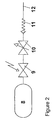
- the means for injecting the tracer gas into the enclosure comprise at least one reservoir (8) containing the tracer gas, the latter being at a pressure higher than that prevailing in the blast furnace, a valve (9) with response rapid remote-controlled and an element (10) creating a pressure drop in order to control the flow injected, preferably the element (10) is an adjustment valve or an orifice calibrated, possibly associated with a non-return valve (11) intended to prevent backflow gas present at the injection point, i.e. the hot wind if the injection takes place at the level a nozzle or blast furnace gas if the injection takes place at a point on the wall, preferably a probe (12) or rod for injecting the tracer gas into the blast furnace.
- the means for withdrawing the gas present in the blast furnace includes one or more probes or rods sample.
- the means for managing the various operations necessary for carrying out the process of the invention comprise at least one computer or similar equipment controlling the sequence of different sequences such as opening or closing valves, collecting measurements supplied by the detector (s) and assuming the operations for calculating the delay between the opening of the tracer gas injection valve and its detection as a function of the point of sampling as well as archiving and calibration operations.
- the probe is replaced (4) or double-walled sampling rod whose inner tube (17) is used to take the sample and the outer tube (16) is used to send the end of the rod (4) a certain quantity of calibration gas, by a sampling probe or cane double-walled whose outer tube is used for sampling and the tube inside is used to send a certain amount of gas at the end of the cane calibration.
- the probe is replaced (4) or double-walled sampling rod whose inner tube (17) is used for take the sample and the outer tube (16) is used to send at the end of cane (4) a certain amount of calibration gas, by a probe or cane double-walled sample whose outer tube is used to sample and the inner tube is used to send a certain amount of gas at the end of the cane calibration.
- a sampling probe is used double wall with an inner tube such as its opening on the sample side gas is recessed from the outer tube.
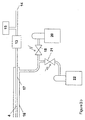
- the representation is made in Figure 4, allowing in particular the calibration using a single tube sampling probe, said device comprises a probe (4) connected to a device (13) for conditioning the sampled gas, said probe (4) is also connected on the one hand to a tank (22) containing the purge gas via a valve (21), and on the other hand to a device (15) for analyzing the sampled gas and to an exhaust (14) via a valve (23), a pressure gauge (24) being connected to the common point of the valves (21) and (23).
Landscapes
- Engineering & Computer Science (AREA)
- Chemical & Material Sciences (AREA)
- Manufacturing & Machinery (AREA)
- Materials Engineering (AREA)
- Metallurgy (AREA)
- Organic Chemistry (AREA)
- Sampling And Sample Adjustment (AREA)
- Blast Furnaces (AREA)
- Other Investigation Or Analysis Of Materials By Electrical Means (AREA)
Claims (13)
- Verfahren für die Laufzeitmessung von Gasen in einem Behälter, bei dem folgende Vorgänge mindestens einmal durchgeführt werden :indem eine Probenahmesonde oder ein Probenahmerohr verwendet wird, bestehend aus mindestens zwei Rohren, von denen ein erstes Rohr, das nicht der Probenahme dient, für das Einspritzen des vorgenannten Prüfgases verwendet wird und ein zweites Rohr für die Entnahme des im Behälter im Augenblick der Probenahme vorhandenen Gases verwendet wird, dadurch gekennzeichnet, dass die Kalibrierungsmessung mittels der folgenden Vorgänge durchgeführt wird:Einspritzen eines sogenannten Prüfgases an einem Punkt A oder A' des Behälters,Entnahme des an einem Punkt B dieses Behälters vorhandenen Gases, wobei Punkt B nicht identisch mit Punkt A oder A' ist,Analyse mit einer Detektor- und Analyseeinrichtung, ob die in B entnommene Gasprobe Prüfgas enthält,Messung der Reaktionszeit der Einrichtung, die die Probenahme in B durchführt in situ, die sogenannte Prozesskalibrierung, wobei diese Messung darin besteht, am Punkt B für die zu kalibrierende Vorrichtung eine bestimmte Gasmenge einzuspritzen und die Zeit zu messen, die zwischen dem Einspritzen und der Erfassung des vorgenannten Gases in der Probenahme- und Detektoreinrichtung verstreicht,Ableitung der Zeit, die das Prüfgas vom Punkt A oder A' bis zum Punkt B benötigt, aus den Daten, die mit den Detektorvorrichtungen über das Prüfgas gewonnen wurden,1) ein Gasgemisch, das aus einem Gas, vorzugsweise Neutralgas, und einem Prüfgas besteht, wird in geringer Menge in das erste Rohr gespritzt, wobei dieses Gemisch am Ende des Probenahmerohrs zum Behälter hin entweicht,2) über das zweite Rohr wird das Gas des Behälters, das sich mit dem Prüfgas vermischt hat, entnommen, wobei das zweite Rohr mit den Detektorvorrichtungen verbunden ist,3) zu einem Zeitpunkt t0 wird ein plötzlicher Druckanstieg des vorstehend genannten Gemischs herbeigeführt, wobei sich der Druckanstieg im ersten Rohr bis zu seinem offenen Ende ausbreitet und dort zu einem Zeitpunkt t1 eine Erhöhung der Durchflussmenge hervorruft,4) es wird der Zeitpunkt t2 bestimmt, zu dem die Änderung der Prüfgaskonzentration im Gemisch durch die Analysevorrichtung, mit der das zweite Rohr verbunden ist, erfasst wird,5) es wird die Laufzeit in der Probenahmevorrichtung durch die Operation t2-t0 ermittelt.
- Verfahren gemäß Anspruch 1, bei dem das Gas im Behälter Prüfgas in einer messbaren Konzentration enthält, dadurch gekennzeichnet, dass ein Gasgemisch verwendet wird, das kein Prüfgas enthält und dadurch, dass die gleichen Vorgänge 1) bis 5) wie zuvor durchgeführt werden.
- Verfahren für die Laufzeitmessung von Gasen in einem Behälter, bei dem folgende Vorgänge mindestens einmal durchgeführt werden :indem eine Probenahmesonde oder ein Probenahmerohr verwendet wird, bestehend aus mindestens zwei Rohren, von denen ein erstes Rohr, das nicht der Probenahme dient, für das Einspritzen des vorgenannten Prüfgases verwendet wird und ein zweites Rohr für die Entnahme des im Behälter im Augenblick der Probenahme vorhandenen Gases verwendet wird, dadurch gekennzeichnet, dass die Kalibrierungsmessung mittels der folgenden Vorgänge durchgeführt wird:Einspritzen eines sogenannten Prüfgases an einem Punkt A oder A' des Behälters,Entnahme des an einem Punkt B dieses Behälters vorhandenen Gases, wobei Punkt B nicht identisch mit Punkt A oder A' ist,Analyse mit einer Detektor- und Analyseeinrichtung, ob die in B entnommene Gasprobe Prüfgas enthält,Messung der Reaktionszeit der Einrichtung, die die Probenahme in B durchführt in situ, die sogenannte Prozesskalibrierung, wobei diese Messung darin besteht, am Punkt B für die zu kalibrierende Vorrichtung eine bestimmte Gasmenge einzuspritzen und die Zeit zu messen, die zwischen dem Einspritzen und der Erfassung des vorgenannten Gases in der Probenahme- und Detektoreinrichtung verstreicht,Ableitung der Zeit, die das Prüfgas vom Punkt A oder A' bis zum Punkt B benötigt, aus den Daten, die mit den Detektorvorrichtungen über das Prüfgas gewonnen wurden,1) ein sogenanntes Kalibriergas, das kein Prüfgas enthält oder nur einen geringen Anteil, wird mit einer Leistung eingespritzt, bei der die Strömungsgeschwindigkeit des Gases im ersten Rohr viel höher ist als die des Gases im zweiten Rohr, vorzugsweise 3-4 Mal so hoch,2) zu einem Zeitpunkt t0 wird ein Impuls oder eine zusätzliche Menge des Prüfgases in das Kalibriergas gesandt, das in das erste Rohr eingeströmt ist, welches zu einem Zeitpunkt t1 an das Ende dieses Rohres und daher an den Eingang des Probenahmerohrs gelangt, wo es teilweise vom zweiten Rohr dieses Probenahmerohrs angesaugt wird,3) zu einem Zeitpunkt t2 wird die Änderung der Prüfgaskonzentration mittels der mit dem Probenahmerohr verbundenen Analysevorrichtung festgestellt,4) es wird die Laufzeit in der Probenahmevorrichtung durch die Operation t2-t0 ermittelt.
- Verfahren nach Anspruch 1, 2 oder 3, dadurch gekennzeichnet, dass man eine Probenahmesonde oder ein Probenahmerohr verwendet, bestehend aus zwei koaxialen Rohren, wobei ein erstes Rohr so angeschlossen ist, dass das Einspritzen des Prüfgases oder Gasgemischs durchgeführt werden kann und ein zweites Rohr so, dass das im Behälter vorhandene Gas entnommen werden kann.
- Verfahren für die Laufzeitmessung von Gasen in einem Behälter, bei dem folgende Vorgänge mindestens einmal durchgeführt werden:bei dem man eine Kalibrierung durch Einsatz einer Probenahmesonde mit einem einzigen Rohr durchführt, wobei dies dann angewandt wird, wenn der Gehalt des analysierten Bestandteils des Behältergases ausreichend verschieden von dem Gehalt dieses Bestandteils in einem sogenannten Spülgas ist, damit der Übergang vom einen zum anderen durch das Analysesystem erkennbar ist, wobei ein Absperrventil im Probenahmekreis angebracht ist, dadurch gekennzeichnet, dass folgende Vorgänge durchgeführt werden:Einspritzen eines sogenannten Prüfgases an einem Punkt A oder A' des Behälters,Entnahme des an einem Punkt B dieses Behälters vorhandenen Gases, wobei Punkt B nicht identisch mit Punkt A oder A' ist,Analyse mit einer Detektor- und Analyseeinrichtung, ob die in B entnommene Gasprobe Prüfgas enthält,Messung der Reaktionszeit der Einrichtung, die die Probenahme in B durchführt in situ, die sogenannte Prozesskalibrierung, wobei diese Messung darin besteht, am Punkt B für die zu kalibrierende Vorrichtung eine bestimmte Gasmenge einzuspritzen und die Zeit zu messen, die zwischen dem Einspritzen und der Erfassung des vorgenannten Gases in der Probenahme- und Detektoreinrichtung verstreicht,Ableitung der Zeit, die das Prüfgas vom Punkt A oder A' bis zum Punkt B benötigt, aus den Daten, die mit den Detektorvorrichtungen über das Prüfgas gewonnen wurden,1) man öffnet das Absperrventil, das sich im Kreislauf der Probenahmevorrichtung befindet, so dass diese mit der Analysevorrichtung in Verbindung ist,2) man öffnet ein Spülventil, so dass in den besagten Probenahmekreislauf ein sogenanntes Spülgas strömen kann, das sich vom Gas im Behälter durch einen seiner Bestandteile unterscheidet, der von der Analysevorrichtung selektiv erkannt werden kann, wobei dieser Vorgang für eine ausreichend lange Zeit durchgeführt wird, um den gesamten Rohrleitungsabschnitt vom Spülventil bis zum Detektor einschließlich der Analysevorrichtung für die Gasprobe zu spülen,3) anschließend schließt man das Absperrventil im Probenahmekreislauf und wartet, bis sich der Spülvorgang zum Behälter hin fortsetzt, und zwar für eine genügend lange Zeit, damit die Leitungen und Geräte zwischen dem Absperrventil und der Probenahmesonde vollständig mit Spülgas gefüllt sind, so dass sowohl im Probenahme- wie auch im Aufbereitungskreislauf für die Gasprobe jede Spur das Behältergases entfernt wird,4) anschließend schließt man das Spülventil und wartet, bis der Druck im Probenahmekreislauf beim Spülventil dem Druck im Behälter entspricht,5) man öffnet das Absperrventil im Probenahmekreislauf zum Zeitpunkt t0 und erfasst den Zeitpunkt t1, an dem die Analysevorrichtung für die Zusammensetzung der Gasprobe den Bestandteil des Behältergases registriert, auf den sie reagiert,6) man bestimmt die Laufzeit in der Probenahmevorrichtung durch die Operation t1-t0.
- Verfahren gemäß Anspruch 5, dadurch gekennzeichnet, dass die Dauerspülung aus Phase 3 der vorstehenden Bedingung durch eine diskontinuierliche Spülung ersetzt wird.
- Verfahren nach einem der Ansprüche 1 bis 6, dadurch gekennzeichnet, dass man eine Durchflussmessvorrichtung verwendet, um die Durchflussmenge in einem oder mehreren bei der Messung verwendeten Teilen fortlaufend oder sequenziell zu messen, dass man die zeitabhängig erfassten Werte in den einzelnen Kreisläufen miteinander vergleicht und dass man entweder eine neue Kalibrierung durchführt, sobald die Messwerte um mehr als 10% vom zuletzt an derselben Stelle gemessenen Wert abweichen oder eine mathematische Interpolationsoperation zur Korrektur der durchgeführten Laufzeitmessungen in Abhängigkeit von den zuvor in der gleichen Vorrichtung gemessenen Werten durchführt.
- Vorrichtung zur Anwendung des Verfahrens zur Laufzeitmessung von Gasen in einem Hochofen nach einem der Ansprüche 1, 2 oder 4, die Mittel umfasst, um ein Prüfgas in die Charge des Hochofens einzuspritzen, sowie Mittel, um eine Probe des im Hochofen vorhandenen Gases zu entnehmen und Mittel, um die Gasprobe zu analysieren, dadurch gekennzeichnet, dass sie folgendes umfasst:eine doppelwandige Probenahmesonde oder ein Probenahmerohr (4), bestehend aus einem Innenrohr (17), das für die Probenahme verwendet wird, und einem Außenrohr (16), das dazu dient, eine bestimmte Menge Kalibriergas an das Ende des Probenahmerohrs (4) zu leiten,einen Behälter (20), der in Bezug auf das Innere des Hochofens unter Überdruck steht und ein Spülgas enthält, wobei das vorstehend genannte Außenrohr (16) mit diesem einerseits über ein erstes ferngesteuertes Ventil (18) und andererseits über ein zweites ferngesteuertes Ventil (19) verbunden ist, das sich in einem Kreislauf befindet, der so konzipiert ist, dass er einen wesentlich geringeren Druckverlust aufweist, als der Kreislauf des ersten Ventils (18),einen Detektor (15), der mit dem Innenrohr (17) der Sonde (4) über eine Gasprobenaufbereitungseinheit (13) verbunden ist.
- Vorrichtung zur Anwendung des Verfahrens zur Laufzeitmessung von Gasen in einem Hochofen nach einem der Ansprüche 3 oder 4, die Mittel umfasst, um ein Prüfgas in die Charge des Hochofens einzuspritzen, sowie Mittel, um eine Probe des im Hochofen vorhandenen Gases zu entnehmen und Mittel, um die Gasprobe zu analysieren, dadurch gekennzeichnet, dass sie folgendes umfasst:eine doppelwandige Probenahmesonde oder ein Probenahmerohr (4), bestehend aus einem Innenrohr (17), das für die Probenahme verwendet wird, und einem Außenrohr (16), das dazu dient, eine bestimmte Menge Kalibriergas an das Ende des Probenahmerohrs (4) zu leiten,einerseits einen Behälter (22), der ein Kalibriergas enthält und mit dem Außenrohr (16) des Probenahmerohrs (4) über ein ferngesteuertes Ventil (21) verbunden ist und andererseits einen Behälter (20), der ein Prüfgas enthält, und ebenfalls mit dem Außenrohr (16) über ein Ventil (18) verbunden ist,eine Gasprobenaufbereitungsvorrichtung (13), die mit dem Innenrohr (17) des Probenahmerohrs (4) verbunden ist und deren Ausgang einerseits mit einer Analysevorrichtung (15) und andererseits einem Abzug (14) verbunden ist.
- Vorrichtung nach Anspruch 8 oder 9, dadurch gekennzeichnet, dass die Mittel zum Einspritzen des Prüfgases in die Charge des Hochofens mindestens einen Behälter (8) mit Prüfgas, in welchem ein höherer Druck als im Hochofen herrscht, ein schnellschaltendes, ferngesteuertes Ventil (9) und ein Element (10), das einen Druckverlust zur Kontrolle der Einspritzmenge herbeiführt, umfassen, wobei das Element (10) vorzugsweise ein Regulierventil oder eine kalibrierte Öffnung ist, eventuell in Verbindung mit einem Rückschlagventil (11), das den Rückfluss des an der Einspritzstelle vorhandenen Gases verhindern soll, das heißt des Heißwindes, wenn der Einspritzvorgang in einer Windform stattfindet, oder des Gichtgases, wenn der Einspritzvorgang in den Hochofen an einer Stelle in der Hochofenwand stattfindet, vorzugsweise über eine Prüfgaseinspritzsonde oder -rohr (12).
- Vorrichtung nach Anspruch 8 oder 9, dadurch gekennzeichnet, dass die doppelwandige Probenahmesonde oder das Probenahmerohr (4), dessen Innenrohr (17) für die Probenahme verwendet wird und dessen Außenrohr (16) dazu dient, eine bestimmte Menge Kalibriergas an das Ende des Probenahmerohrs (4) zu leiten, durch eine doppelwandige Probenahmesonde oder Probenahmerohr (4), dessen Außenrohr für die Probenahme verwendet wird und dessen Innenrohr dazu dient, eine bestimmte Menge Kalibriergas an das Ende des Probenahmerohrs (4) zu leiten, ersetzt wird.
- Vorrichtung nach einem der Ansprüche 8 bis 10, dadurch gekennzeichnet, dass die doppelwandige Probenahmesonde (4) ein Innenrohr enthält, bei dem die Öffnung zur Gasprobenahme im Vergleich zum Außenrohr weiter innen liegt.
- Vorrichtung zur Anwendung des Verfahrens zur Laufzeitmessung von Gasen in einem Hochofen nach Anspruch 5 oder 6, die Mittel umfasst, um ein Prüfgas in die Charge des Hochofens einzuspritzen, sowie Mittel, um eine Probe des im Hochofen vorhandenen Gases zu entnehmen und Mittel, um die Gasprobe zu analysieren, dadurch gekennzeichnet, dass sie eine Probenahmesonde (4) mit einem einzigen Rohr umfasst, wobei die Sonde (4) mit einer Vorrichtung (13) zur Aufbereitung der Gasprobe verbunden ist, sowie einerseits über ein Ventil (21) mit einem Behälter (22), der Spülgas enthält, und andererseits über ein Ventil (23) mit einer Gasprobenanalysevorrichtung (15) und einem Abzug (14), wobei ein Manometer (24) am gemeinsamen Punkt dieser Ventile (21, 23) angeschlossen ist.
Applications Claiming Priority (3)
| Application Number | Priority Date | Filing Date | Title |
|---|---|---|---|
| BE9701043A BE1011630A3 (fr) | 1997-12-19 | 1997-12-19 | Procede et dispositif de mesure du temps de transfert des gaz au sein d'une enceinte, en particulier un four a cuve. |
| BE9701043 | 1997-12-19 | ||
| PCT/BE1998/000150 WO1999032665A1 (fr) | 1997-12-19 | 1998-10-13 | Procede et dispositif de mesure du temps de transfert des gaz au sein d'une enceinte, en particulier un four a cuve. |
Publications (2)
| Publication Number | Publication Date |
|---|---|
| EP0963448A1 EP0963448A1 (de) | 1999-12-15 |
| EP0963448B1 true EP0963448B1 (de) | 2004-05-26 |
Family
ID=3890922
Family Applications (1)
| Application Number | Title | Priority Date | Filing Date |
|---|---|---|---|
| EP98948626A Expired - Lifetime EP0963448B1 (de) | 1997-12-19 | 1998-10-13 | Verfahren und vorrichtung für die laufzeitmessung von gasen in einem behälter, insbesondere einem schachtofen |
Country Status (6)
| Country | Link |
|---|---|
| EP (1) | EP0963448B1 (de) |
| AT (1) | ATE267880T1 (de) |
| BE (1) | BE1011630A3 (de) |
| DE (1) | DE69824156T2 (de) |
| ES (1) | ES2221205T3 (de) |
| WO (1) | WO1999032665A1 (de) |
Families Citing this family (1)
| Publication number | Priority date | Publication date | Assignee | Title |
|---|---|---|---|---|
| IT201900020470A1 (it) * | 2019-11-06 | 2021-05-06 | Danieli Off Mecc | Procedimento per la rilevazione di perdite di acqua da forni fusori in impianti di produzione di metalli o leghe e relativo impianto |
Family Cites Families (4)
| Publication number | Priority date | Publication date | Assignee | Title |
|---|---|---|---|---|
| JPS5764111A (en) * | 1980-10-07 | 1982-04-19 | Nippon Steel Corp | Method for measuring distribution of gaseous flow in blast furnace |
| JPS599116A (ja) * | 1982-07-07 | 1984-01-18 | Nippon Steel Corp | 高炉内測定方法 |
| JPS6049267A (ja) * | 1983-08-29 | 1985-03-18 | Nippon Steel Corp | 炉内等のガス流速測定方法 |
| US5672827A (en) * | 1995-06-07 | 1997-09-30 | American Air Liquide Inc. | Method for measuring the flow rate of a species contained in an exhaust gas stream of a combustion process |
-
1997
- 1997-12-19 BE BE9701043A patent/BE1011630A3/fr not_active IP Right Cessation
-
1998
- 1998-10-13 WO PCT/BE1998/000150 patent/WO1999032665A1/fr not_active Ceased
- 1998-10-13 ES ES98948626T patent/ES2221205T3/es not_active Expired - Lifetime
- 1998-10-13 AT AT98948626T patent/ATE267880T1/de not_active IP Right Cessation
- 1998-10-13 DE DE69824156T patent/DE69824156T2/de not_active Expired - Fee Related
- 1998-10-13 EP EP98948626A patent/EP0963448B1/de not_active Expired - Lifetime
Also Published As
| Publication number | Publication date |
|---|---|
| EP0963448A1 (de) | 1999-12-15 |
| WO1999032665A1 (fr) | 1999-07-01 |
| DE69824156T2 (de) | 2005-06-23 |
| ATE267880T1 (de) | 2004-06-15 |
| ES2221205T3 (es) | 2004-12-16 |
| DE69824156D1 (de) | 2004-07-01 |
| BE1011630A3 (fr) | 1999-11-09 |
Similar Documents
| Publication | Publication Date | Title |
|---|---|---|
| EP0399876B1 (de) | Verfahren und Vorrichtung zur Bestimmung der Eigenschaften einer mehrphasigen Flüssigkeit | |
| EP0184521B1 (de) | Verfahren und Vorrichtung zum Feststellen von Lecken in einem Wärmetauscher während des Betriebes | |
| KR101009741B1 (ko) | 밸브 유체누설 모의시험장치 | |
| US20110153225A1 (en) | In-line composition and volumetric analysis of vent gases and flooding of the annular space of flexible pipe | |
| EP0437141B1 (de) | Verfahren und Vorrichtung zur Auswertung der Permeabilität eines Körpers und ihre Verwendung in der Auswertung der Dysmigration | |
| US4328700A (en) | Leak detection method and apparatus | |
| EP0829719B1 (de) | Verfahren und Vorrichtung zur Auswertung einer Kontaminationskarakteristik einer Bodenprobe. | |
| US5363692A (en) | Device and method for evaluating the ability of a body containing a product to expel the product from the body | |
| CN119064098B (zh) | 一种天然气取样和组分分析系统 | |
| BE1011630A3 (fr) | Procede et dispositif de mesure du temps de transfert des gaz au sein d'une enceinte, en particulier un four a cuve. | |
| EP0370873B1 (de) | Verfahren und Einrichtung für die Analyse einer durch eine Leitung strömenden mehrphasigen Flüssigkeit | |
| CA1159923A (fr) | Mesure du niveau de la scorie dans un recipient metallurgique | |
| JP5055504B2 (ja) | オイルミスト濃度測定装置 | |
| FR2671225A1 (fr) | Procede et dispositif de mesure de la temperature du fluide de refroidissement primaire d'un reacteur nucleaire. | |
| AU2017381037B2 (en) | Optimised method for detecting the formation of gas hydrates | |
| US20040112122A1 (en) | BS&W metering apparatus & method | |
| Brouwer et al. | Modelling hydrogen induced crack growth: validation by comparison with experiment | |
| CA1109739A (en) | Leak detection method and apparatus | |
| Pratap et al. | Blockage detection in gas pipelines to prevent failure of transmission line | |
| JPS61179808A (ja) | 溶鉱炉の連続制御方法および設備 | |
| FR2675581A1 (fr) | Dispositif et methode d'evaluation de l'aptitude qu'a un corps a expulser un produit et du maintien de produit genere lors de la maturation artificielle du corps. | |
| FR2741716A1 (fr) | Procede et dispositif de mise a l'epreuve d'une citerne | |
| JP3944252B2 (ja) | 不飽和型重合体の水添方法 | |
| FR2833018A1 (fr) | Methode de conduite et de controle de procedes de traitement thermique de produits dans des fours continus | |
| Gurunathan et al. | Reliability Enhancement in Nondestructive Evaluation: Development of Practical Rules for Vacuum Type Helium Leak Tests |
Legal Events
| Date | Code | Title | Description |
|---|---|---|---|
| PUAI | Public reference made under article 153(3) epc to a published international application that has entered the european phase |
Free format text: ORIGINAL CODE: 0009012 |
|
| 17P | Request for examination filed |
Effective date: 19990713 |
|
| AK | Designated contracting states |
Kind code of ref document: A1 Designated state(s): AT BE DE ES FR GB IT NL |
|
| 17Q | First examination report despatched |
Effective date: 20010605 |
|
| GRAH | Despatch of communication of intention to grant a patent |
Free format text: ORIGINAL CODE: EPIDOS IGRA |
|
| GRAS | Grant fee paid |
Free format text: ORIGINAL CODE: EPIDOSNIGR3 |
|
| GRAA | (expected) grant |
Free format text: ORIGINAL CODE: 0009210 |
|
| RAP1 | Party data changed (applicant data changed or rights of an application transferred) |
Owner name: CENTRE DE RECHERCHES METALLURGIQUES - CENTRUM VOOR |
|
| AK | Designated contracting states |
Kind code of ref document: B1 Designated state(s): AT BE DE ES FR GB IT NL |
|
| REG | Reference to a national code |
Ref country code: GB Ref legal event code: FG4D Free format text: NOT ENGLISH |
|
| REF | Corresponds to: |
Ref document number: 69824156 Country of ref document: DE Date of ref document: 20040701 Kind code of ref document: P |
|
| GBT | Gb: translation of ep patent filed (gb section 77(6)(a)/1977) |
Effective date: 20040721 |
|
| REG | Reference to a national code |
Ref country code: ES Ref legal event code: FG2A Ref document number: 2221205 Country of ref document: ES Kind code of ref document: T3 |
|
| PLBE | No opposition filed within time limit |
Free format text: ORIGINAL CODE: 0009261 |
|
| STAA | Information on the status of an ep patent application or granted ep patent |
Free format text: STATUS: NO OPPOSITION FILED WITHIN TIME LIMIT |
|
| 26N | No opposition filed |
Effective date: 20050301 |
|
| PGFP | Annual fee paid to national office [announced via postgrant information from national office to epo] |
Ref country code: GB Payment date: 20051004 Year of fee payment: 8 |
|
| PGFP | Annual fee paid to national office [announced via postgrant information from national office to epo] |
Ref country code: AT Payment date: 20051021 Year of fee payment: 8 |
|
| PGFP | Annual fee paid to national office [announced via postgrant information from national office to epo] |
Ref country code: BE Payment date: 20051024 Year of fee payment: 8 |
|
| PGFP | Annual fee paid to national office [announced via postgrant information from national office to epo] |
Ref country code: NL Payment date: 20051025 Year of fee payment: 8 |
|
| PGFP | Annual fee paid to national office [announced via postgrant information from national office to epo] |
Ref country code: FR Payment date: 20051027 Year of fee payment: 8 Ref country code: DE Payment date: 20051027 Year of fee payment: 8 |
|
| PGFP | Annual fee paid to national office [announced via postgrant information from national office to epo] |
Ref country code: ES Payment date: 20051108 Year of fee payment: 8 |
|
| PG25 | Lapsed in a contracting state [announced via postgrant information from national office to epo] |
Ref country code: AT Free format text: LAPSE BECAUSE OF NON-PAYMENT OF DUE FEES Effective date: 20061013 |
|
| PGFP | Annual fee paid to national office [announced via postgrant information from national office to epo] |
Ref country code: IT Payment date: 20061031 Year of fee payment: 9 |
|
| PG25 | Lapsed in a contracting state [announced via postgrant information from national office to epo] |
Ref country code: NL Free format text: LAPSE BECAUSE OF NON-PAYMENT OF DUE FEES Effective date: 20070501 Ref country code: DE Free format text: LAPSE BECAUSE OF NON-PAYMENT OF DUE FEES Effective date: 20070501 |
|
| GBPC | Gb: european patent ceased through non-payment of renewal fee |
Effective date: 20061013 |
|
| NLV4 | Nl: lapsed or anulled due to non-payment of the annual fee |
Effective date: 20070501 |
|
| REG | Reference to a national code |
Ref country code: FR Ref legal event code: ST Effective date: 20070629 |
|
| PG25 | Lapsed in a contracting state [announced via postgrant information from national office to epo] |
Ref country code: GB Free format text: LAPSE BECAUSE OF NON-PAYMENT OF DUE FEES Effective date: 20061013 |
|
| BERE | Be: lapsed |
Owner name: *CENTRE DE RECHERCHES METALLURGIQUES- CENTRUM VOOR Effective date: 20061031 |
|
| REG | Reference to a national code |
Ref country code: ES Ref legal event code: FD2A Effective date: 20061014 |
|
| PG25 | Lapsed in a contracting state [announced via postgrant information from national office to epo] |
Ref country code: FR Free format text: LAPSE BECAUSE OF NON-PAYMENT OF DUE FEES Effective date: 20061031 Ref country code: ES Free format text: LAPSE BECAUSE OF NON-PAYMENT OF DUE FEES Effective date: 20061014 |
|
| PG25 | Lapsed in a contracting state [announced via postgrant information from national office to epo] |
Ref country code: IT Free format text: LAPSE BECAUSE OF NON-PAYMENT OF DUE FEES Effective date: 20071013 Ref country code: BE Free format text: LAPSE BECAUSE OF FAILURE TO SUBMIT A TRANSLATION OF THE DESCRIPTION OR TO PAY THE FEE WITHIN THE PRESCRIBED TIME-LIMIT Effective date: 20061031 |