EP0963764A1 - Selbstsichernder Katheter und Einführungsvorrichtung - Google Patents
Selbstsichernder Katheter und Einführungsvorrichtung Download PDFInfo
- Publication number
- EP0963764A1 EP0963764A1 EP98304684A EP98304684A EP0963764A1 EP 0963764 A1 EP0963764 A1 EP 0963764A1 EP 98304684 A EP98304684 A EP 98304684A EP 98304684 A EP98304684 A EP 98304684A EP 0963764 A1 EP0963764 A1 EP 0963764A1
- Authority
- EP
- European Patent Office
- Prior art keywords
- catheter
- self
- retaining
- wire
- aperture
- Prior art date
- Legal status (The legal status is an assumption and is not a legal conclusion. Google has not performed a legal analysis and makes no representation as to the accuracy of the status listed.)
- Withdrawn
Links
- 239000012530 fluid Substances 0.000 claims abstract description 79
- 210000004204 blood vessel Anatomy 0.000 claims abstract description 55
- 238000002347 injection Methods 0.000 claims abstract description 27
- 239000007924 injection Substances 0.000 claims abstract description 27
- 238000004804 winding Methods 0.000 claims abstract description 26
- 230000002093 peripheral effect Effects 0.000 claims abstract description 14
- 238000003780 insertion Methods 0.000 claims description 13
- 230000037431 insertion Effects 0.000 claims description 13
- 210000000056 organ Anatomy 0.000 abstract description 49
- 210000001367 artery Anatomy 0.000 description 13
- 210000004185 liver Anatomy 0.000 description 10
- 230000003327 cancerostatic effect Effects 0.000 description 9
- 230000017531 blood circulation Effects 0.000 description 6
- 238000011282 treatment Methods 0.000 description 6
- 239000000853 adhesive Substances 0.000 description 5
- 230000001070 adhesive effect Effects 0.000 description 5
- 238000000034 method Methods 0.000 description 5
- 206010028980 Neoplasm Diseases 0.000 description 4
- 201000011510 cancer Diseases 0.000 description 4
- 230000000694 effects Effects 0.000 description 4
- 230000010102 embolization Effects 0.000 description 4
- 230000000717 retained effect Effects 0.000 description 4
- 239000008280 blood Substances 0.000 description 3
- 210000004369 blood Anatomy 0.000 description 3
- 210000001124 body fluid Anatomy 0.000 description 3
- 239000010839 body fluid Substances 0.000 description 3
- 238000007796 conventional method Methods 0.000 description 3
- -1 polyethylene Polymers 0.000 description 3
- 229910001285 shape-memory alloy Inorganic materials 0.000 description 3
- 229910052751 metal Inorganic materials 0.000 description 2
- 239000002184 metal Substances 0.000 description 2
- BASFCYQUMIYNBI-UHFFFAOYSA-N platinum Chemical compound [Pt] BASFCYQUMIYNBI-UHFFFAOYSA-N 0.000 description 2
- 229920005989 resin Polymers 0.000 description 2
- 239000011347 resin Substances 0.000 description 2
- 210000002563 splenic artery Anatomy 0.000 description 2
- 239000010935 stainless steel Substances 0.000 description 2
- 229910001220 stainless steel Inorganic materials 0.000 description 2
- 229920003002 synthetic resin Polymers 0.000 description 2
- 239000000057 synthetic resin Substances 0.000 description 2
- JOYRKODLDBILNP-UHFFFAOYSA-N Ethyl urethane Chemical compound CCOC(N)=O JOYRKODLDBILNP-UHFFFAOYSA-N 0.000 description 1
- 239000004677 Nylon Substances 0.000 description 1
- 239000004698 Polyethylene Substances 0.000 description 1
- 239000004743 Polypropylene Substances 0.000 description 1
- 229910001260 Pt alloy Inorganic materials 0.000 description 1
- 208000007536 Thrombosis Diseases 0.000 description 1
- 230000036760 body temperature Effects 0.000 description 1
- 201000010099 disease Diseases 0.000 description 1
- 208000037265 diseases, disorders, signs and symptoms Diseases 0.000 description 1
- 210000001105 femoral artery Anatomy 0.000 description 1
- 230000007774 longterm Effects 0.000 description 1
- 238000003754 machining Methods 0.000 description 1
- 238000002844 melting Methods 0.000 description 1
- 230000008018 melting Effects 0.000 description 1
- 150000002739 metals Chemical class 0.000 description 1
- 229920001778 nylon Polymers 0.000 description 1
- 230000000737 periodic effect Effects 0.000 description 1
- 239000004033 plastic Substances 0.000 description 1
- 229920003023 plastic Polymers 0.000 description 1
- 229910052697 platinum Inorganic materials 0.000 description 1
- 229920000573 polyethylene Polymers 0.000 description 1
- 229920001155 polypropylene Polymers 0.000 description 1
- 229920001296 polysiloxane Polymers 0.000 description 1
- 230000001012 protector Effects 0.000 description 1
- 230000002787 reinforcement Effects 0.000 description 1
- 238000003466 welding Methods 0.000 description 1
Images



Classifications
-
- A—HUMAN NECESSITIES
- A61—MEDICAL OR VETERINARY SCIENCE; HYGIENE
- A61M—DEVICES FOR INTRODUCING MEDIA INTO, OR ONTO, THE BODY; DEVICES FOR TRANSDUCING BODY MEDIA OR FOR TAKING MEDIA FROM THE BODY; DEVICES FOR PRODUCING OR ENDING SLEEP OR STUPOR
- A61M25/00—Catheters; Hollow probes
- A61M25/0067—Catheters; Hollow probes characterised by the distal end, e.g. tips
- A61M25/0068—Static characteristics of the catheter tip, e.g. shape, atraumatic tip, curved tip or tip structure
-
- A—HUMAN NECESSITIES
- A61—MEDICAL OR VETERINARY SCIENCE; HYGIENE
- A61M—DEVICES FOR INTRODUCING MEDIA INTO, OR ONTO, THE BODY; DEVICES FOR TRANSDUCING BODY MEDIA OR FOR TAKING MEDIA FROM THE BODY; DEVICES FOR PRODUCING OR ENDING SLEEP OR STUPOR
- A61M25/00—Catheters; Hollow probes
- A61M25/01—Introducing, guiding, advancing, emplacing or holding catheters
- A61M25/02—Holding devices, e.g. on the body
- A61M25/04—Holding devices, e.g. on the body in the body, e.g. expansible
-
- A—HUMAN NECESSITIES
- A61—MEDICAL OR VETERINARY SCIENCE; HYGIENE
- A61M—DEVICES FOR INTRODUCING MEDIA INTO, OR ONTO, THE BODY; DEVICES FOR TRANSDUCING BODY MEDIA OR FOR TAKING MEDIA FROM THE BODY; DEVICES FOR PRODUCING OR ENDING SLEEP OR STUPOR
- A61M25/00—Catheters; Hollow probes
- A61M25/01—Introducing, guiding, advancing, emplacing or holding catheters
- A61M25/02—Holding devices, e.g. on the body
- A61M2025/0293—Catheter, guide wire or the like with means for holding, centering, anchoring or frictionally engaging the device within an artificial lumen, e.g. tube
-
- A—HUMAN NECESSITIES
- A61—MEDICAL OR VETERINARY SCIENCE; HYGIENE
- A61M—DEVICES FOR INTRODUCING MEDIA INTO, OR ONTO, THE BODY; DEVICES FOR TRANSDUCING BODY MEDIA OR FOR TAKING MEDIA FROM THE BODY; DEVICES FOR PRODUCING OR ENDING SLEEP OR STUPOR
- A61M25/00—Catheters; Hollow probes
- A61M25/0021—Catheters; Hollow probes characterised by the form of the tubing
- A61M25/0041—Catheters; Hollow probes characterised by the form of the tubing pre-formed, e.g. specially adapted to fit with the anatomy of body channels
-
- A—HUMAN NECESSITIES
- A61—MEDICAL OR VETERINARY SCIENCE; HYGIENE
- A61M—DEVICES FOR INTRODUCING MEDIA INTO, OR ONTO, THE BODY; DEVICES FOR TRANSDUCING BODY MEDIA OR FOR TAKING MEDIA FROM THE BODY; DEVICES FOR PRODUCING OR ENDING SLEEP OR STUPOR
- A61M25/00—Catheters; Hollow probes
- A61M25/0067—Catheters; Hollow probes characterised by the distal end, e.g. tips
- A61M25/008—Strength or flexibility characteristics of the catheter tip
-
- A—HUMAN NECESSITIES
- A61—MEDICAL OR VETERINARY SCIENCE; HYGIENE
- A61M—DEVICES FOR INTRODUCING MEDIA INTO, OR ONTO, THE BODY; DEVICES FOR TRANSDUCING BODY MEDIA OR FOR TAKING MEDIA FROM THE BODY; DEVICES FOR PRODUCING OR ENDING SLEEP OR STUPOR
- A61M25/00—Catheters; Hollow probes
- A61M25/0067—Catheters; Hollow probes characterised by the distal end, e.g. tips
- A61M25/0082—Catheter tip comprising a tool
Definitions
- the present invention relates to a self-retaining catheter that is arranged to be retained in a blood vessel or the like of a patient and to permit a medical fluid, for example such as a carcinostatic, to be injected on a periodic basis, and an inserting apparatus thereof.
- a medical fluid for example such as a carcinostatic
- the medical fluid for administration of such a medical fluid as a carcinostatic, for example, the medical fluid was administered into a blood vessel conventionally by use of an injection syringe or a drip. In that case, the medical fluid circulated through blood vessels in the body, and thus there was the fear of damaging the normal cells in addition to cancerous cells.
- embolization coils or the like were inserted into inlets of the arteries branched to the other normal organs so as to temporarily obstruct the blood flow, so that the medical fluid could flow into only the organ affected by cancer.
- catheters having the structure capable of retaining themselves not only in the blood vessels, but also in tubular organs of the human body
- an example of such catheters is the one described in Japanese Patent Application Laid-open No. 5-192389, in which the catheter is comprised of an outside tube, an inside tube, and a reinforcement interposed between them, and in which a flap projecting to engage an inner wall of a tubular organ of the human body is mounted on the periphery of the leading end of the outside tube.
- Another known example is the one described in Japanese Utility Model Application Laid-open No. 5-86355, in which a plurality of fins are arranged at intervals on the periphery of the leading end or an intermediate section of the catheter so as to act as a cushion, a seal, a stopper, and a protector.
- An object of the present invention is to provide a self-retaining catheter whose leading end can be fixed to an inner wall of a tubular organ such as a blood vessel, that causes little damage to the inner wall of the tubular organ during insertion and during withdrawal, and that causes little obstruction against the blood flow or the like in the self-retaining state, and also to provide an inserting apparatus of the self-retaining catheter.
- a self-retaining catheter comprises a tubular catheter body, and an elastic wire of a winding shape buried in one end portion of the catheter body, wherein the end portion of the catheter body with the wire inside is in a winding state.
- Another embodiment of the self-retaining catheter according to the present invention comprises a tubular catheter body, and an elastic wire of a winding shape greater than an outside diameter of the catheter body, wherein said wire is connected to one end of the catheter body so as to project outwardly from the catheter body.
- the self-retaining catheter causes little damage to the inner wall of the tubular organ and does not obstruct the blood flow or the like, from the same reasons as described above.
- the catheter can be constructed in such a structure that the catheter body linearly extends from a position in a periphery of the winding shape of the wire.
- this structure when the leading end of the catheter body is fixed inside the tubular organ such as the blood vessel, the base side of the catheter body extends from the position in the periphery of the winding shape of the leading end and along the inner wall of the tubular organ. Therefore, this structure causes little obstruction to flow of the body fluid such as the blood flow and can prevent occurrence of a thrombus or the like.
- the catheter can be constructed in such a structure that an aperture for outflow of a medical fluid is formed in a peripheral wall of the catheter body near the end where the wire is mounted, the aperture is formed in a slit shape, the aperture is opened when a pressure of the fluid inside is applied thereto, and the aperture is closed when the pressure of the fluid inside is not applied thereto.
- the medical fluid changes its direction so as to flow sideways out of the aperture formed in the peripheral wall. This restrains the medical fluid from hitting the inner wall of the tubular organ such as the blood vessel with strong force and in turn, it can avoid obstruction of a flow passage or the like due to the damage to the inner wall of the blood vessel or the like. Since the aperture is of the slit shape and is opened only when the pressure of the fluid inside is applied thereto, the body fluid such as the blood can be prevented from flowing back through the catheter during the periods in which the medical fluid is not injected.
- the medical fluid introduced into the catheter advanced along the axis of the catheter and flowed straight out of the leading end thereof.
- the conventional methods had the problem that the medical fluid hit the inner wall of the blood vessel, the blood vessel absorbed the medical fluid, it damaged the inner wall of the blood vessel, and it was likely to cause obstruction in the blood vessel.
- the medical fluid is, however, prevented from directly hitting the inner wall of the blood vessel or the like with strong force, which can prevent the obstruction due to the damage to the inner wall of the blood vessel or the like.
- the self-retaining catheter can be constructed in such a structure that an aperture for outflow of the medical fluid is formed in a peripheral wall of the catheter body near the end where the wire is mounted and that the aperture is formed as being directed toward the center of the winding shape of the wire, in the peripheral wall of the catheter body.
- the medical fluid is prevented from strongly hitting the inner wall of the tubular organ, because the aperture is directed toward the center of the tubular organ. Thus there occurs little damage to the inner wall.
- the self-retaining catheter can be constructed in such a structure that a contrast chip is mounted near the aperture of the catheter body.
- a position of the medical fluid injection aperture can be detected with accuracy, and the medical treatment can be carried out more precisely.
- a self-retaining catheter inserting apparatus comprises the self-retaining catheter according to the present invention, a core wire arranged to be detachably inserted into the self-retaining catheter, and a master catheter having an inside diameter that permits insertion of the self-retaining catheter.
- the self-retaining catheter can be guided to a predetermined portion in a tubular organ through the master catheter, and the self-retaining catheter can be fixed in the tubular organ by restoring force of the wire when the leading end of the self-retaining catheter is made to project out of the master catheter.
- the insertion operation of the self-retaining catheter can be facilitated with increase in the stiffness thereof by inserting the core wire into the self-retaining catheter.
- Another embodiment of the self-retaining catheter inserting apparatus comprises the self-retaining catheter according to the present invention, a core wire arranged to be detachably inserted into this self-retaining catheter, a master catheter having an inside diameter that permits insertion of the self-retaining catheter, and a sheath for percutaneous insertion of the master catheter into a blood vessel.
- the sheath is first percutaneously inserted into the blood vessel, the master catheter is then inserted through this sheath, the leading end of this master catheter is guided to a desired portion in the blood vessel, and the self-retaining catheter is inserted through this master catheter. Therefore, the insertion operation of the self-retaining catheter into the blood vessel can be performed surely and readily.
- a further embodiment of the self-retaining catheter inserting apparatus comprises the self-retaining catheter according to the present invention, a core wire arranged to be detachably inserted into the self-retaining catheter, a master catheter having an inside diameter that permits insertion of the self-retaining catheter, a sheath for percutaneous insertion of the master catheter into a blood vessel, and a medical fluid injection port to be embedded in the body while being connected to a base end of the self-retaining catheter.
- the sheath is first percutaneously inserted into the blood vessel, the master catheter is then inserted through this sheath, and the leading end of this master catheter is guided to a desired portion in the blood vessel. Thereafter the self-retaining catheter is inserted through the master catheter, and the leading end of the self-retaining catheter is made to project out of the master catheter to be fixed to the inner wall of the blood vessel. Then the master catheter is drawn out, the medical fluid injection port is connected to the base end of the self-retaining catheter, and this medical fluid injection port is embedded under the skin.
- an injection needle can be stuck into the medical fluid injection port when necessary and the medical fluid can be injected readily into the affected region of the target, which extremely reduces the load on the patient.
- the self-retaining catheter When the self-retaining catheter is withdrawn, the master catheter is inserted along the periphery of the self-retaining catheter. Then the self-retaining catheter is pulled to the base side relative to the master catheter, so as to retract the self-retaining catheter into the master catheter while stretching the leading end of the self-retaining catheter.
- This simple operation permits the self-retaining catheter to be withdrawn, and thus the withdrawal (evulsion) of the self-retaining catheter can be performed readily.
- Fig. 1 illustrates an embodiment of the self-retaining catheter according to the present invention.
- This self-retaining catheter 10 has a tubular catheter body 11, for example, made of a synthetic resin such as urethane, nylon, polyethylene, polypropylene, or silicone, or a shape memory alloy, or the like.
- a closure 13 which permits a core wire 12 to be inserted in a sealed state into the catheter body 11, is mounted at the base end of the catheter body 11.
- the core wire 12 can be selected from wires of shape memory alloys, stainless steel, or the like, guide wires, and so on.
- the inside and/or the outside of the catheter body is preferably coated with a hydrophilic resin in order to enhance a sliding property of the core wire 12 to the catheter body 11 or in order to increase a sliding property of the catheter body 11 to a master catheter described hereinafter.
- a coil wire 14 having higher stiffness than the catheter body 11 is buried inside the leading end of the catheter body 11.
- the wire 14 is made of a shape memory alloy treated by such a shape memory treatment as to exhibit superelasticity near body temperatures of the human body in the case of this embodiment, but the wire 14 may also be selected from wires of other metals such as stainless steel, wires of FRP with high stiffness, and so on.
- An outside diameter of the coil wire 14 in a free state is a diameter sufficiently larger than an inside diameter A of a self-retaining portion such as an objective blood vessel (see Fig. 11A).
- the catheter body 11 In the state in which the coil wire 14 is interpolated in the catheter body 11, the catheter body 11 is also in a winding shape like a coil having an outside diameter B larger than the inside diameter A of the self-retaining portion. Since the wire 14 has superelasticity while the catheter body 11 is made of a plastic pipe, they can be elastically deformed, so that they can be put inside an inside diameter C of the master catheter 51 (see Fig. 11A). In this state they can be inserted into a blood vessel or the like. A ring contrast chip 20 is mounted at the leading end of the catheter body 11.
- the leading end of the wire 14 is fixed inside the catheter body 11 with an adhesive 15. This prevents the wire 14 from moving inside the catheter body 11.
- a distance a between the tip of the fixing part of wire 14 and the tip of the catheter body 11 is preferably 5-50 mm and most preferably about 20 mm. This range provides the leading end of the catheter body 11 with flexibility and thus prevents the leading end from damaging the inner wall of the blood vessel or the like.
- the size of the catheter body 11 may be properly determined depending upon an applied object, but, for example in the case of those for liver arteries of adults, the outside diameter b is preferably 0.3-2 mm and the inside diameter c is preferably 0.1-1.7 mm.
- Figs. 3A to 3C show other examples of the fixing structure of the leading end of wire 14.
- a coil 16 is disposed around the periphery of the leading end of the wire 14, and the adhesive 15 is deposited so as to bury the coil 16 and the leading end of the wire 14, whereby the leading end of the wire 14 is fixed to the catheter body 11.
- the coil 16 makes it easier to deposit the adhesive 15 and reduces the clearance between the wire 14 and the inner wall of the catheter body 11, so as to enhance the fixing strength.
- a contrast chip 17 having a ring shape or a C-shaped cross section is put inside the catheter body 11, the leading end of the wire 14 is put in this contrast chip 17, and the leading end of the wire 14 is fixed by caulking of the contrast chip 17.
- a contrast chip 18 having a ring shape or a C-shaped cross section is mounted on the periphery of the leading end of the catheter body 11, and the leading end of the wire 14 is fastened through the catheter body 11 by caulking of this contrast chip 18.
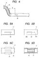
- an aperture 21 of a slit shape is formed in a peripheral wall a distance d apart from the base end of the wire 14 in the catheter body 11 to the base of the catheter body 11.
- the length of d is suitably set depending upon an applied portion, but it is normally 1-15 cm.
- the self-retaining catheters may be supplied in a selling form without the aperture 21, and the aperture 21 of the slit shape may be formed depending upon patient's conditions, for example by urging the tip of a knife or the like against the peripheral wall of the catheter body 11 to cut it immediately before an operation.
- the aperture 21 can be suitably formed by such working as to cut the wall with a knife or an edged tool having a fine edge. If the aperture 21 were made, for example, by machining with a grinder or the like, a part of the wall would be lost, so as to form an aperture always open. Therefore, the valve effect (the effect that the aperture is opened only when the pressure of the fluid is applied inside) would not be achieved well.
- Figs. 5A to 5D show other examples of the aperture.
- an aperture 22 is formed in a predetermined width.
- an aperture 23 is formed in a predetermined width and is tapered at the both ends 23a, 23b.
- a contrast chip 19 having a C-shaped cross section is mounted so as not to cover the aperture 21, on the periphery of the portion of the catheter body 11 where the aperture 21 is present, whereby the contrast chip 19 prevents the catheter body 11 from being crushed in the portion of aperture 21.
- a contrast chip 19 also having a C-shaped cross section is set so as not to close the aperture 21, on the inside surface of the portion where the aperture 21 is formed in the catheter body 11, whereby the contrast chip 19 prevents the catheter body 11 from being crushed in that portion.
- Fig. 6 is a perspective view to show an enlarged view of the leading end of the self-retaining catheter 10.
- the leading end of the self-retaining catheter 10 is kept in the winding state of the coil shape by the wire 14 (not illustrated in Fig. 6) disposed inside the catheter body 11 as long as no external force is exerted thereon.
- the base side of the catheter body 11 linearly extends from a position in a periphery of this coil winding portion. Because of this shape, when the self-retaining catheter is set in a tubular organ such as a blood vessel, the base side of the catheter body 11 extends along the inner wall of the tubular organ and thus is arranged so as not to be positioned in the center of the lumen of the tubular organ.
- the aperture 21 formed in the peripheral wall of the catheter body 11 is open while being directed in the direction A toward the center of the coil winding portion. This allows the aperture 21 to be directed inwardly of the tubular organ when the catheter is inserted into the tubular organ such as the blood vessel.
- This structure is free of the problem that when the medical fluid is allowed to flow through the aperture 21, the medical fluid is ejected strongly against the intima of the tubular organ to be directly absorbed through the intima, or the aperture is pushed against the intima of the tubular organ to interfere ejection of the medical fluid.
- contrast chip 20 is provided at the leading end of the catheter body 11, another contrast chip 20' may also be mounted near the aperture 21 in place of this contrast chip 20 or together with the contrast chip 20. This allows the position of the aperture through which the medical fluid is ejected, to be detected more accurately.
- contrast chips 20, 20' may also be located in the catheter body 11.
- the aperture 21' may be formed on the inside of the winding portion of the spiral shape, instead of the aperture 21 formed in the straight portion of the catheter body 11.
- the medical fluid is introduced through the clearance between the internal surface of the catheter body 11 and the wire 14 to the spirally winding portion of the catheter body 11 to flow out through the aperture 21'.
- Fig. 7 illustrates the relation between the wire 14 and the core wire 12 in the self-retaining catheter 10.
- the base end of the wire 14 extends toward the base of the catheter body 11, and the leading end of the core wire 12 extends toward the tip of the catheter body 11 and has such a thickness as to abut against the base end of the wire 14.
- This structure allows a pushing force to be occur in the self-retaining catheter 10 when the core wire 12 is forced into the catheter body 11.
- Fig. 8 illustrates another embodiment of the self-retaining catheter according to the present invention. Substantially identical portions to those in the embodiment shown in Fig. 1 will be denoted by the same reference numerals and the description thereof will be omitted herein.
- a swirl of wire 32 is put inside the leading end of the catheter body 11 and the leading end of the wire 32 is fixed to the catheter body 11 with the adhesive 15.
- the catheter body 11 is kept in a swirl shape by the stiffness of the wire 32 as long as no external force is exerted thereon.
- the base side of the catheter body 11 also linearly extends from the periphery of the swirl winding portion and the aperture 20 is open as directed toward the center of the winding portion.
- a variety of shapes can be employed for the winding shape of the wire.
- Fig. 9 illustrates still another embodiment of the self-retaining catheter according to the present invention.
- one end of wire 41 of a coil shape is connected to the leading end of the catheter body 11 and the wire 41 projects out of the catheter body 11.
- the diameter of the coil of wire 41 is larger than the outside diameter of the catheter body 11 and a contrast chip 42 is formed at the tip of the wire 41 by melting the wire in a ball shape or by welding a metal not transmitting X-rays, such as platinum or a platinum alloy, to the tip.
- This contrast chip 42 also presents the effect of preventing the inner wall of the tubular organ from being damaged.
- the outside surface of the wire 41 is preferably coated with an organism-compatible resin.
- the base end of the wire 41 is formed in a small coil shape, put in the catheter body 11, and fixed thereto with the adhesive 15.
- the base side of the catheter body 11 also linearly extends from the periphery of the wire 41 of the coil shape and the aperture 21 formed in the peripheral wall of the catheter body 11 is open as being directed to the center of the coil shape of the wire 41.
- the wire as a fixing means to the tubular organ may project outwardly from the catheter body 11.
- Fig. 10 is an explanatory drawing to show a state in which the self-retaining catheter 10 is percutaneously inserted into a blood vessel;
- Figs. 11A to 11E are explanatory drawings to show procedures for inserting the self-retaining catheter 10 through the master catheter into the blood vessel and allowing the medical fluid to flow out;
- Fig. 12 is an explanatory drawing to show a state in which the leading end of the self-retaining catheter 10 is set at an objective portion of a blood vessel and fixed there;
- Fig. 13 is an explanatory drawing to schematically show an enlarged state in which the leading end of the self-retaining catheter 10 is set at the objective portion of the blood vessel and fixed there;
- Fig. 14 is an explanatory drawing to show a state in which the master catheter is withdrawn;
- Fig. 15 is a perspective view to show a medical fluid injection port;
- Fig. 16 is an explanatory drawing to show a state in which the medical fluid injection port is buried under the skin and in which the medical fluid is
- numeral 51 designates the skin and 52 a blood vessel (the femoral artery in this example).
- a sheath 53 is percutaneously inserted into the blood vessel 52 by the known Seldinger method.
- the master catheter 55 is inserted through a closure 54 provided at the base end of the sheath 53.
- a guide wire not illustrated is inserted through a closure 56 provided at the base end of the master catheter 55. After the leading end of the guide wire reaches an objective portion of a blood vessel, the leading end of the master catheter 55 is forced ahead along the guide wire up to the aforementioned portion, and then the guide wire is pulled out.
- the self-retaining catheter 10 is inserted through the closure 56 provided at the base end of the master catheter 55 and the core wire 12 is inserted through the closure 13 provided at the base end of the self-retaining catheter 10. Then the self-retaining catheter 10 is forced into the master catheter 55 while the stiffness is maintained by the core wire 12. For example, supposing the size of the sheath 53 is 5 Fr (French size), the size of the master catheter 55 is 4 Fr.
- the leading end of the self-retaining catheter 10 inserted into the master catheter 55 passes in the master catheter 55 while the coil wire 14 inside the catheter body 11 is stretched in a wave shape.
- the leading end of the self-retaining catheter 10 elastically returns to the original coil diameter in the free state from the depressed state where it is limited to the inside diameter of the master catheter 55. Then the leading end of the self-retaining catheter 10 is elastically urged against the inner wall of the blood vessel 52.
- Fig. 11C shows a state in which the master catheter 55 is drawn out by the above operation and Fig. 11D shows a state in which the core wire 12 is pulled out and the medical fluid is injected into the self-retaining catheter 10 to flow out through the aperture 21.
- Fig. 11E is a sectional view along line e-e in Fig. 11D, which shows a state in which the medical fluid is flowing out toward the center of the blood vessel 52.
- 52a designates the right liver artery to which the carcinostatic is expected to be administered, 52b the left liver artery, 52c the gastroduodenal artery, and 52d the splenic artery. It can also be contemplated that, prior to the administration of the carcinostatic, the embolization coils or the like are preliminarily inserted into blood vessels branched to normal organs to temporarily embolize those blood vessels so as to prevent the medical fluid containing the carcinostatic from flowing into the normal organs.
- the leading end of the self-retaining catheter 10 is set, for example, in the right liver artery 52a to be fixed as being expanded by the restoring force of the wire 14 and being urged against the inner wall of the blood vessel in that portion.
- the aperture 21 of the self-retaining catheter 10 is located at a branch point into the right liver artery 52a and the left liver artery 52b so that the medical fluid flowing through the aperture 21 can flow mainly in directions to the entire liver. Since the leading end of the self-retaining catheter 10 is fixed in the blood vessel, there is no possibility of a positional shift of the aperture 21 even if the patient turns his body thereafter.
- the core wire 12 is withdrawn and the master catheter 55 is further withdrawn, thereby establishing the state in which only the self-retaining catheter 10 is put in the sheath 53, as shown in Fig. 14.
- the closure 54 of the sheath 53 and the closure 13 side of the self-retaining catheter 10 are disconnected, so as to project the self-retaining catheter 10 out from the base portion of the sheath 53.
- the base portion of the self-retaining catheter 10 thus cut is connected to a medical fluid outlet 62 of a medical fluid injection port 61.
- the medical fluid injection port 61 is constructed in such a structure that a container 63 having a truncated cone shape is made of a synthetic resin having a hardness too high for the injection needle or the like to pierce, a rubber film 64, through which the injection needle or the like can be stuck, is mounted in an aperture of the top surface of the container 63, and the aforementioned medical fluid outlet 62 is formed in the side wall of the container 63.
- the medical fluid injection port 61 is buried inside the skin 51.
- the base portion of the sheath 53 cut is fastened to the self-retaining catheter 10 with thread 65 or the like, thereby preventing the blood from leaking from that portion.
- the patient can live the daily life as being allowed to move freely.
- the catheter will not shift in the body, because the leading end of the self-retaining catheter 10 is fixed as shown in Fig. 12 and Fig. 13.
- the injection needle 71 of the injection syringe 70 is stuck through the skin 51 into the rubber film 64 of the medical fluid injection port 61 and the medical fluid in which the carcinostatic is dissolved is injected into the medical fluid injection port 61.
- This medical fluid flows out of the medical fluid outlet 62 into the self-retaining catheter 10 and flows out through the aperture 21 of the self-retaining catheter 10. Then the medical fluid can be selectively injected into the liver affected by cancer.
- the medical fluid advances along the axis of the catheter in the self-retaining catheter 10 and then turns the direction to flow out sideways through the aperture 21 provided in the peripheral wall of the self-retaining catheter 10. Therefore, the medical fluid is prevented from strongly hitting the inner wall of the blood vessel, and there is thus little damage to the inner wall of the blood vessel.
- a plurality of fine self-retaining catheters of about 1.5 Fr are simultaneously set through one blood vessel and are retained at different portions inside the human body.
- only medical fluids necessary for a plurality of organs can be simultaneously injected and administered to the respective organs; for example, a medical fluid A is administered to the liver arteries, a medical fluid B to the gastroduodenal artery, and a medical fluid C to the splenic artery. This can remarkably enhance the treatment effects on a patient suffering combined diseases and can decrease the treatment period.
Landscapes
- Health & Medical Sciences (AREA)
- Life Sciences & Earth Sciences (AREA)
- Biophysics (AREA)
- Pulmonology (AREA)
- Engineering & Computer Science (AREA)
- Anesthesiology (AREA)
- Biomedical Technology (AREA)
- Heart & Thoracic Surgery (AREA)
- Hematology (AREA)
- Animal Behavior & Ethology (AREA)
- General Health & Medical Sciences (AREA)
- Public Health (AREA)
- Veterinary Medicine (AREA)
- Media Introduction/Drainage Providing Device (AREA)
Priority Applications (3)
| Application Number | Priority Date | Filing Date | Title |
|---|---|---|---|
| JP09657797A JP3274384B2 (ja) | 1997-03-31 | 1997-03-31 | 留置カテーテル及びその挿入装置 |
| US09/093,373 US6074378A (en) | 1997-03-31 | 1998-06-08 | Self-retaining catheter and inserting apparatus thereof |
| EP98304684A EP0963764A1 (de) | 1997-03-31 | 1998-06-12 | Selbstsichernder Katheter und Einführungsvorrichtung |
Applications Claiming Priority (3)
| Application Number | Priority Date | Filing Date | Title |
|---|---|---|---|
| JP09657797A JP3274384B2 (ja) | 1997-03-31 | 1997-03-31 | 留置カテーテル及びその挿入装置 |
| US09/093,373 US6074378A (en) | 1997-03-31 | 1998-06-08 | Self-retaining catheter and inserting apparatus thereof |
| EP98304684A EP0963764A1 (de) | 1997-03-31 | 1998-06-12 | Selbstsichernder Katheter und Einführungsvorrichtung |
Publications (1)
| Publication Number | Publication Date |
|---|---|
| EP0963764A1 true EP0963764A1 (de) | 1999-12-15 |
Family
ID=27239535
Family Applications (1)
| Application Number | Title | Priority Date | Filing Date |
|---|---|---|---|
| EP98304684A Withdrawn EP0963764A1 (de) | 1997-03-31 | 1998-06-12 | Selbstsichernder Katheter und Einführungsvorrichtung |
Country Status (3)
| Country | Link |
|---|---|
| US (1) | US6074378A (de) |
| EP (1) | EP0963764A1 (de) |
| JP (1) | JP3274384B2 (de) |
Cited By (9)
| Publication number | Priority date | Publication date | Assignee | Title |
|---|---|---|---|---|
| WO2001026725A1 (en) * | 1999-10-13 | 2001-04-19 | Prolifix Medical, Inc. | Guidewire for positioning a catheter against a lumen wall |
| WO2001076675A3 (en) * | 2000-04-11 | 2002-05-16 | Scimed Life Systems Inc | Reinforced retention structures |
| EP1327459A1 (de) * | 2002-01-14 | 2003-07-16 | CODMAN & SHURTLEFF, INC. | Antihaftkatheter |
| EP1464296A1 (de) * | 2003-04-01 | 2004-10-06 | Cryocor, Inc. | Katheter zur Kryoablation mit einer Kryospitze, die eine spiralförmige und eine gerade Konfiguration ausweist |
| WO2006068927A3 (en) * | 2004-12-20 | 2007-09-20 | Advanced Cardiovascular System | Methods and apparatuses for positioning within an internal channel |
| WO2011140177A1 (en) * | 2010-05-05 | 2011-11-10 | Cook Medical Technologies Llc | Intraluminal treatment apparatus, wire guide and treatment fluid delivery method |
| US8545380B2 (en) | 2006-09-14 | 2013-10-01 | Circulite, Inc. | Intravascular blood pump and catheter |
| US9555215B2 (en) | 2010-05-05 | 2017-01-31 | Cook Medical Technologies Llc | Treatment fluid delivery method, and turbulator for promoting uptake of a treatment agent |
| WO2019195287A1 (en) * | 2018-04-02 | 2019-10-10 | Transmural Systems Llc | Helical guidewires and related systems |
Families Citing this family (79)
| Publication number | Priority date | Publication date | Assignee | Title |
|---|---|---|---|---|
| US6530946B1 (en) | 1998-04-21 | 2003-03-11 | Alsius Corporation | Indwelling heat exchange heat pipe catheter and method of using same |
| US6149670A (en) * | 1999-03-11 | 2000-11-21 | Alsius Corporation | Method and system for treating cardiac arrest using hypothermia |
| US6458150B1 (en) * | 1999-02-19 | 2002-10-01 | Alsius Corporation | Method and apparatus for patient temperature control |
| US6682551B1 (en) | 1999-03-11 | 2004-01-27 | Alsius Corporation | Method and system for treating cardiac arrest using hypothermia |
| JP3524788B2 (ja) | 1998-12-24 | 2004-05-10 | 株式会社パイオラックス | 制癌剤投与用体内留置カテーテル |
| US6405080B1 (en) | 1999-03-11 | 2002-06-11 | Alsius Corporation | Method and system for treating cardiac arrest |
| US6702811B2 (en) | 1999-04-05 | 2004-03-09 | Medtronic, Inc. | Ablation catheter assembly with radially decreasing helix and method of use |
| JP3810603B2 (ja) | 1999-11-30 | 2006-08-16 | 株式会社パイオラックスメディカルデバイス | 医療用チューブ加工治具 |
| US6500185B1 (en) * | 2000-09-29 | 2002-12-31 | Primus Medical, Inc. | Snare device |
| US6652471B2 (en) * | 2001-11-28 | 2003-11-25 | Scimed Life Systems, Inc. | Pressure-sensing guidewire having improved torque |
| US7876294B2 (en) * | 2002-03-05 | 2011-01-25 | Nec Corporation | Image display and its control method |
| US7653438B2 (en) | 2002-04-08 | 2010-01-26 | Ardian, Inc. | Methods and apparatus for renal neuromodulation |
| US20140018880A1 (en) | 2002-04-08 | 2014-01-16 | Medtronic Ardian Luxembourg S.A.R.L. | Methods for monopolar renal neuromodulation |
| US8774913B2 (en) | 2002-04-08 | 2014-07-08 | Medtronic Ardian Luxembourg S.A.R.L. | Methods and apparatus for intravasculary-induced neuromodulation |
| US7338433B2 (en) | 2002-08-13 | 2008-03-04 | Allergan, Inc. | Remotely adjustable gastric banding method |
| BR0306183A (pt) | 2002-08-28 | 2004-10-19 | Inamed Medical Products Corp | Dispositivo de enfaixamento gástrico resistente à fadiga |
| US20040256172A1 (en) * | 2003-06-23 | 2004-12-23 | Darling Dean William | Shape-retaining stethoscope tubing |
| AU2005208721B2 (en) | 2004-01-23 | 2010-09-23 | Boston Scientific Scimed, Inc. | Releasably-securable one-piece adjustable gastric band |
| DK1725193T3 (da) | 2004-03-08 | 2009-11-30 | Allergan Medical S A | Lukkesystem til rörformede organer |
| ATE517652T1 (de) * | 2004-03-18 | 2011-08-15 | Allergan Inc | Vorrichtung zur volumeneinstellung intragastraler ballons |
| US8205565B2 (en) * | 2005-03-04 | 2012-06-26 | Cemex, Inc. | Apparatus and method for injecting waste tires through the burner end of a kiln |
| US8251888B2 (en) | 2005-04-13 | 2012-08-28 | Mitchell Steven Roslin | Artificial gastric valve |
| WO2007006055A2 (en) | 2005-07-06 | 2007-01-11 | Vascular Pathways Inc. | Intravenous catheter insertion device and method of use |
| US7798954B2 (en) | 2006-01-04 | 2010-09-21 | Allergan, Inc. | Hydraulic gastric band with collapsible reservoir |
| US8043206B2 (en) | 2006-01-04 | 2011-10-25 | Allergan, Inc. | Self-regulating gastric band with pressure data processing |
| WO2008070769A1 (en) * | 2006-12-06 | 2008-06-12 | Medtronic, Inc. | Intrathecal catheter |
| WO2008122048A2 (en) * | 2007-04-02 | 2008-10-09 | University Of Pittsburgh - Of The Commonwealth System Of Higher Education | Removal of contrast agents from blood |
| JP5139518B2 (ja) | 2007-05-07 | 2013-02-06 | バスキュラー・パスウェイズ・インコーポレイテッド | 静脈カテーテル挿入装置 |
| JP2007252960A (ja) * | 2007-06-29 | 2007-10-04 | Kaneka Corp | バルーンカテーテル用保護具 |
| US9622731B2 (en) * | 2008-01-28 | 2017-04-18 | Baxter International Inc. | Sealant applicator with malleable section |
| US8317677B2 (en) | 2008-10-06 | 2012-11-27 | Allergan, Inc. | Mechanical gastric band with cushions |
| US20100185049A1 (en) | 2008-10-22 | 2010-07-22 | Allergan, Inc. | Dome and screw valves for remotely adjustable gastric banding systems |
| US8758221B2 (en) | 2010-02-24 | 2014-06-24 | Apollo Endosurgery, Inc. | Source reservoir with potential energy for remotely adjustable gastric banding system |
| US8840541B2 (en) | 2010-02-25 | 2014-09-23 | Apollo Endosurgery, Inc. | Pressure sensing gastric banding system |
| US9044298B2 (en) | 2010-04-29 | 2015-06-02 | Apollo Endosurgery, Inc. | Self-adjusting gastric band |
| US9028394B2 (en) | 2010-04-29 | 2015-05-12 | Apollo Endosurgery, Inc. | Self-adjusting mechanical gastric band |
| US20110270024A1 (en) | 2010-04-29 | 2011-11-03 | Allergan, Inc. | Self-adjusting gastric band having various compliant components |
| US20110270025A1 (en) | 2010-04-30 | 2011-11-03 | Allergan, Inc. | Remotely powered remotely adjustable gastric band system |
| US10384039B2 (en) | 2010-05-14 | 2019-08-20 | C. R. Bard, Inc. | Catheter insertion device including top-mounted advancement components |
| US11925779B2 (en) | 2010-05-14 | 2024-03-12 | C. R. Bard, Inc. | Catheter insertion device including top-mounted advancement components |
| US9950139B2 (en) | 2010-05-14 | 2018-04-24 | C. R. Bard, Inc. | Catheter placement device including guidewire and catheter control elements |
| US8932258B2 (en) | 2010-05-14 | 2015-01-13 | C. R. Bard, Inc. | Catheter placement device and method |
| US9872971B2 (en) | 2010-05-14 | 2018-01-23 | C. R. Bard, Inc. | Guidewire extension system for a catheter placement device |
| US8517915B2 (en) | 2010-06-10 | 2013-08-27 | Allergan, Inc. | Remotely adjustable gastric banding system |
| US20120059216A1 (en) | 2010-09-07 | 2012-03-08 | Allergan, Inc. | Remotely adjustable gastric banding system |
| JP2013544133A (ja) | 2010-10-25 | 2013-12-12 | メドトロニック アーディアン ルクセンブルク ソシエテ ア レスポンサビリテ リミテ | 腎ニューロモジュレーションのためのマルチ電極アレイを有するカテーテル装置ならびに関連のシステムおよび方法 |
| US8961393B2 (en) | 2010-11-15 | 2015-02-24 | Apollo Endosurgery, Inc. | Gastric band devices and drive systems |
| US8690833B2 (en) | 2011-01-31 | 2014-04-08 | Vascular Pathways, Inc. | Intravenous catheter and insertion device with reduced blood spatter |
| WO2012154277A1 (en) | 2011-02-25 | 2012-11-15 | C.R. Bard, Inc. | Medical component insertion device including a retractable needle |
| USD903101S1 (en) | 2011-05-13 | 2020-11-24 | C. R. Bard, Inc. | Catheter |
| US8876694B2 (en) | 2011-12-07 | 2014-11-04 | Apollo Endosurgery, Inc. | Tube connector with a guiding tip |
| US8961394B2 (en) | 2011-12-20 | 2015-02-24 | Apollo Endosurgery, Inc. | Self-sealing fluid joint for use with a gastric band |
| US8888773B2 (en) | 2012-05-11 | 2014-11-18 | Medtronic Ardian Luxembourg S.A.R.L. | Multi-electrode catheter assemblies for renal neuromodulation and associated systems and methods |
| WO2014081942A1 (en) | 2012-11-21 | 2014-05-30 | Concert Medical, Llc | Preformed guidewire |
| US9095321B2 (en) | 2012-11-21 | 2015-08-04 | Medtronic Ardian Luxembourg S.A.R.L. | Cryotherapeutic devices having integral multi-helical balloons and methods of making the same |
| CN108607150B (zh) | 2013-01-30 | 2021-01-12 | 血管通路股份有限公司 | 用于静脉穿刺和导管放置的系统和方法 |
| US9179974B2 (en) | 2013-03-15 | 2015-11-10 | Medtronic Ardian Luxembourg S.A.R.L. | Helical push wire electrode |
| US20150073515A1 (en) | 2013-09-09 | 2015-03-12 | Medtronic Ardian Luxembourg S.a.r.I. | Neuromodulation Catheter Devices and Systems Having Energy Delivering Thermocouple Assemblies and Associated Methods |
| US10736690B2 (en) | 2014-04-24 | 2020-08-11 | Medtronic Ardian Luxembourg S.A.R.L. | Neuromodulation catheters and associated systems and methods |
| WO2016037127A1 (en) | 2014-09-05 | 2016-03-10 | C.R. Bard, Inc. | Catheter insertion device including retractable needle |
| US9682216B2 (en) | 2014-12-05 | 2017-06-20 | Anchor Endovascular, Inc. | Anchor device for use with catheters |
| USD903100S1 (en) | 2015-05-01 | 2020-11-24 | C. R. Bard, Inc. | Catheter placement device |
| EP3294380B1 (de) | 2015-05-15 | 2022-03-23 | C. R. Bard, Inc. | Kathetereinführvorrichtung |
| US10610669B2 (en) | 2016-03-16 | 2020-04-07 | Krishna Rocha-Singh, M.D. | Apparatus and method for promoting angiogenesis in ischemic tissue |
| US10065018B2 (en) | 2016-03-16 | 2018-09-04 | Krishna Rocha-Singh | Apparatus and method for promoting angiogenesis in ischemic tissue |
| EP3756721B1 (de) | 2016-06-09 | 2022-09-14 | Boston Scientific Scimed Inc. | Infusionskatheter |
| US10493262B2 (en) | 2016-09-12 | 2019-12-03 | C. R. Bard, Inc. | Blood control for a catheter insertion device |
| JP6953541B2 (ja) | 2017-03-01 | 2021-10-27 | シー・アール・バード・インコーポレーテッドC R Bard Incorporated | カテーテル挿入装置 |
| US11389626B2 (en) | 2018-03-07 | 2022-07-19 | Bard Access Systems, Inc. | Guidewire advancement and blood flashback systems for a medical device insertion system |
| USD870880S1 (en) * | 2018-05-29 | 2019-12-24 | Device Therapeutics, Inc. | Indwelling catheter with an archimedean spiral |
| USD921884S1 (en) | 2018-07-27 | 2021-06-08 | Bard Access Systems, Inc. | Catheter insertion device |
| US12274462B2 (en) | 2019-08-01 | 2025-04-15 | Carnelian Medical LLC | Snare device with anti-skewing |
| US11350956B2 (en) | 2019-08-01 | 2022-06-07 | Carnelian Medical LLC | Snare device with anti-skewing |
| JP7721504B2 (ja) | 2019-08-19 | 2025-08-12 | ベクトン・ディキンソン・アンド・カンパニー | 正中線カテーテル配置デバイス |
| EP4025288A1 (de) | 2019-09-20 | 2022-07-13 | Bard Peripheral Vascular, Inc. | Vorrichtung zum legen eines intravenösen katheters |
| US20210393921A1 (en) * | 2020-06-19 | 2021-12-23 | Becton, Dickinson And Company | Probe assembly to reposition a catheter |
| JP7832694B2 (ja) | 2021-03-04 | 2026-03-18 | カーネリアン メディカル エルエルシー | スネア装置 |
| EP4719580A1 (de) * | 2023-08-08 | 2026-04-08 | FBR Medical, Inc. | Katheterblutpumpen mit einem distalen flexiblen rohr mit kreisförmigem abstandshalter |
| US20250235239A1 (en) * | 2024-01-18 | 2025-07-24 | Surgin, Inc. | Cannula with retractable spring-loaded arced tip |
Citations (7)
| Publication number | Priority date | Publication date | Assignee | Title |
|---|---|---|---|---|
| EP0244818A2 (de) * | 1986-05-08 | 1987-11-11 | Terumo Kabushiki Kaisha | Katheter |
| FR2661603A1 (fr) * | 1990-05-02 | 1991-11-08 | Coralines Abj Division Sarl | Prothese anti-stenose des canaux du corps. |
| EP0513991A1 (de) * | 1991-05-17 | 1992-11-19 | C.R. Bard, Inc. | Mehrventil-Katheter mit verbesserter Zuverlässigkeit |
| JPH05192389A (ja) | 1991-10-16 | 1993-08-03 | Olympus Optical Co Ltd | 生体内留置チューブ |
| US5554114A (en) * | 1994-10-20 | 1996-09-10 | Micro Therapeutics, Inc. | Infusion device with preformed shape |
| US5709874A (en) * | 1993-04-14 | 1998-01-20 | Emory University | Device for local drug delivery and methods for using the same |
| US5730741A (en) * | 1997-02-07 | 1998-03-24 | Eclipse Surgical Technologies, Inc. | Guided spiral catheter |
Family Cites Families (6)
| Publication number | Priority date | Publication date | Assignee | Title |
|---|---|---|---|---|
| US4681570A (en) * | 1985-12-26 | 1987-07-21 | Dalton Michael J | Peritoneal catheter |
| JPH0586355A (ja) * | 1991-09-26 | 1993-04-06 | Toyota Motor Corp | 摩擦材組成物 |
| US5282860A (en) * | 1991-10-16 | 1994-02-01 | Olympus Optical Co., Ltd. | Stent tube for medical use |
| US5573508A (en) | 1994-11-22 | 1996-11-12 | Advanced Cardiovascular Systems, Inc. | Catheter with an expandable perfusion lumen |
| US5603694A (en) * | 1995-10-17 | 1997-02-18 | Brown; Joe E. | Infusion coil apparatus and method for delivering fluid-based agents intravascularly |
| US5873865A (en) * | 1997-02-07 | 1999-02-23 | Eclipse Surgical Technologies, Inc. | Spiral catheter with multiple guide holes |
-
1997
- 1997-03-31 JP JP09657797A patent/JP3274384B2/ja not_active Expired - Fee Related
-
1998
- 1998-06-08 US US09/093,373 patent/US6074378A/en not_active Expired - Fee Related
- 1998-06-12 EP EP98304684A patent/EP0963764A1/de not_active Withdrawn
Patent Citations (7)
| Publication number | Priority date | Publication date | Assignee | Title |
|---|---|---|---|---|
| EP0244818A2 (de) * | 1986-05-08 | 1987-11-11 | Terumo Kabushiki Kaisha | Katheter |
| FR2661603A1 (fr) * | 1990-05-02 | 1991-11-08 | Coralines Abj Division Sarl | Prothese anti-stenose des canaux du corps. |
| EP0513991A1 (de) * | 1991-05-17 | 1992-11-19 | C.R. Bard, Inc. | Mehrventil-Katheter mit verbesserter Zuverlässigkeit |
| JPH05192389A (ja) | 1991-10-16 | 1993-08-03 | Olympus Optical Co Ltd | 生体内留置チューブ |
| US5709874A (en) * | 1993-04-14 | 1998-01-20 | Emory University | Device for local drug delivery and methods for using the same |
| US5554114A (en) * | 1994-10-20 | 1996-09-10 | Micro Therapeutics, Inc. | Infusion device with preformed shape |
| US5730741A (en) * | 1997-02-07 | 1998-03-24 | Eclipse Surgical Technologies, Inc. | Guided spiral catheter |
Cited By (17)
| Publication number | Priority date | Publication date | Assignee | Title |
|---|---|---|---|---|
| US6371928B1 (en) | 1997-11-07 | 2002-04-16 | Prolifix Medical, Inc. | Guidewire for positioning a catheter against a lumen wall |
| WO2001026725A1 (en) * | 1999-10-13 | 2001-04-19 | Prolifix Medical, Inc. | Guidewire for positioning a catheter against a lumen wall |
| AU2001289310B2 (en) * | 2000-04-11 | 2006-07-06 | Boston Scientific Limited | Reinforced retention structures |
| WO2001076675A3 (en) * | 2000-04-11 | 2002-05-16 | Scimed Life Systems Inc | Reinforced retention structures |
| US6569150B2 (en) | 2000-04-11 | 2003-05-27 | Scimed Life Systems, Inc. | Reinforced retention structures |
| US7914516B2 (en) | 2000-04-11 | 2011-03-29 | Boston Scientific Scimed, Inc. | Reinforced retention structures |
| US7169139B2 (en) | 2000-04-11 | 2007-01-30 | Boston Scientific Scimed, Inc. | Reinforced retention structures |
| EP1327459A1 (de) * | 2002-01-14 | 2003-07-16 | CODMAN & SHURTLEFF, INC. | Antihaftkatheter |
| US7037288B2 (en) | 2002-01-14 | 2006-05-02 | Codman & Shurtleff, Inc. | Anti-block catheter |
| EP1464296A1 (de) * | 2003-04-01 | 2004-10-06 | Cryocor, Inc. | Katheter zur Kryoablation mit einer Kryospitze, die eine spiralförmige und eine gerade Konfiguration ausweist |
| WO2006068927A3 (en) * | 2004-12-20 | 2007-09-20 | Advanced Cardiovascular System | Methods and apparatuses for positioning within an internal channel |
| EP1859732A1 (de) * | 2004-12-20 | 2007-11-28 | Advanced Cardiovascular Systems, Inc. | Verfahren und Vorrichtungen zur Positionierung innerhalb eines internen Kanals |
| US8983582B2 (en) | 2004-12-20 | 2015-03-17 | Advanced Cardiovascular Systems, Inc. | Methods and apparatuses for positioning within an internal channel |
| US8545380B2 (en) | 2006-09-14 | 2013-10-01 | Circulite, Inc. | Intravascular blood pump and catheter |
| WO2011140177A1 (en) * | 2010-05-05 | 2011-11-10 | Cook Medical Technologies Llc | Intraluminal treatment apparatus, wire guide and treatment fluid delivery method |
| US9555215B2 (en) | 2010-05-05 | 2017-01-31 | Cook Medical Technologies Llc | Treatment fluid delivery method, and turbulator for promoting uptake of a treatment agent |
| WO2019195287A1 (en) * | 2018-04-02 | 2019-10-10 | Transmural Systems Llc | Helical guidewires and related systems |
Also Published As
| Publication number | Publication date |
|---|---|
| US6074378A (en) | 2000-06-13 |
| JP3274384B2 (ja) | 2002-04-15 |
| JPH10272187A (ja) | 1998-10-13 |
Similar Documents
| Publication | Publication Date | Title |
|---|---|---|
| US6074378A (en) | Self-retaining catheter and inserting apparatus thereof | |
| JP3524788B2 (ja) | 制癌剤投与用体内留置カテーテル | |
| US6905481B2 (en) | Percutaneous catheter assembly | |
| CA2489586C (en) | Drainage catheter | |
| US5098412A (en) | Support system for catheter | |
| US4114618A (en) | Catheter assembly | |
| US5308318A (en) | Easy-exchange drainage catheter system with integral obturator channel | |
| EP1598016B1 (de) | Führungsdraht mit lösbarem Anker | |
| USRE46116E1 (en) | Coaxial guide catheter for interventional cardiology procedures | |
| US7981152B1 (en) | Vascular delivery system for accessing and delivering devices into coronary sinus and other vascular sites | |
| US5536261A (en) | Method and closed tip effect catheter apparatus for use in angiography | |
| US20160101265A1 (en) | Medical guide element with diameter transition | |
| JPH11514541A (ja) | 縦方向に延伸可能な注入装置 | |
| AU4173200A (en) | Single operator exchange biliary catheter with common distal lumen | |
| US9220872B2 (en) | Bidirectional vascular introducer sheath | |
| WO1999010023A2 (en) | An apparatus for preventing loss of a composition during a medical procedure | |
| EP3927258B1 (de) | Punktionsortungssystem mit blutpulsationsanzeiger | |
| US20100179588A1 (en) | Vascular puncture closure system with guide sheath stabilizer | |
| US20060200079A1 (en) | Drainage catheter | |
| JP2009142357A (ja) | 体内留置カテーテル | |
| JPH01119266A (ja) | 体腔の内径確保用装置 | |
| US20250195076A1 (en) | Catheter for the Delivery of Y90 to an Individual | |
| JP2000271225A (ja) | 体内埋め込み用シース及び体内埋め込み具 | |
| JPH0426111Y2 (de) | ||
| JP2001178827A (ja) | カテーテル |
Legal Events
| Date | Code | Title | Description |
|---|---|---|---|
| PUAI | Public reference made under article 153(3) epc to a published international application that has entered the european phase |
Free format text: ORIGINAL CODE: 0009012 |
|
| AK | Designated contracting states |
Kind code of ref document: A1 Designated state(s): DE FR GB IT |
|
| AX | Request for extension of the european patent |
Free format text: AL;LT;LV;MK;RO;SI |
|
| 17P | Request for examination filed |
Effective date: 20000327 |
|
| AKX | Designation fees paid |
Free format text: DE FR GB IT |
|
| 17Q | First examination report despatched |
Effective date: 20030806 |
|
| STAA | Information on the status of an ep patent application or granted ep patent |
Free format text: STATUS: THE APPLICATION IS DEEMED TO BE WITHDRAWN |
|
| 18D | Application deemed to be withdrawn |
Effective date: 20040217 |